Pelco dome cameras look like this:
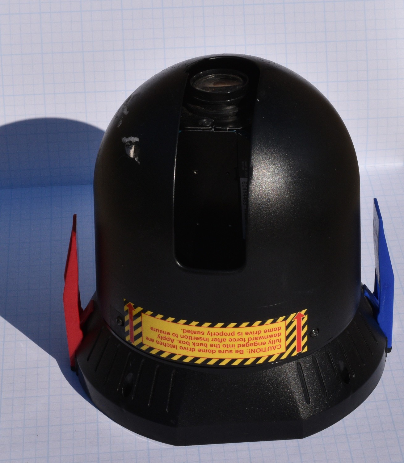
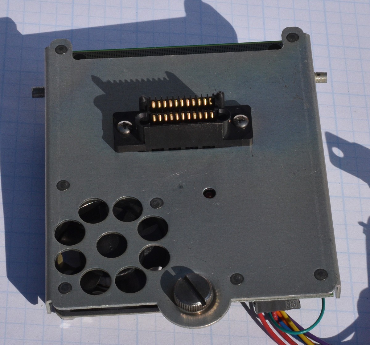
The camera shown snaps into an enclosure with a "base board". The base board breaks out the proprietary connector on the bottom of the camera into terminal strips for connecting to the building wiring. The base board also controls fans and heaters for outdoor use, and has lots of TVS diodes for protecting the camera electronics from electrical transients related to long cable runs.
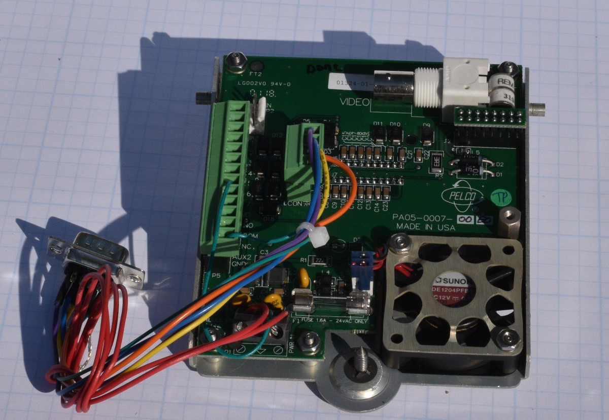
The cameras run on about 24 Volts AC, with the AC line frequency used to synchronize the video framing. This is pretty common in analog surveilance cameras because it allows all of the cameras in a building to be synchronized with each other. This is not an issue with newer IP network cameras, but old school analog cameras needed to be synchronized to allow smoothly switching from camera to camera without complex hardware.
When I got the cameras, they did not come with any enclosures or the baseboards.Starting with the camera in the worst mechanical condition, I reverse engineered enough of the wiring to the connector on the bottom of the camera to hook up power, video and the RS422 signals. I spliced into those wires for testing. I was pleased to see that even the beat up camera would power up, initialize and output video. Once I verified that the cameras appeared to mostly work, I bought a couple of the base boards on the used market so I would not have to cut up the other cameras.
Communications with the camera is done with the RS422/485 physical layer protocol at 2400 Bits/Second no parity and one stop bit. In a past project, I built some USB to RS422/485 boards and had one left over. They are simple, a USB UART chip (FTDI FT230X), an RS422/485 transceiver chip (MAX3086CSD+), a few passives and a connector. FTDI also sells some nicely packaged dongles for this if you don't want to build your own.
Pelco's communication protocol for controlling cameras is called Pelco D Protocol. Searching the net for documents on the Pelco D Protocol turned up an 8 page document that identified the bits and bytes of the protocol, but nothing about how to use it. This document is titled "D Protocol Manual, released March 2 1999.
The protocol in this document looks like it was built in at least 2 iterations. All of the commands are built with 7 bytes:
| Byte 1 | Byte 2 | Byte 3 | Byte 4 | Byte 5 | Byte 6 | Byte 7 |
| Sync Byte 0xFF | Camera Address | Command Byte 1 | Command Byte 2 | Data Byte 1 | Data Byte 2 | Checksum |
Camera Address with the Pelco D Protocol is a number between 0 and 0xFF. The Check Sum is just the sum of bytes 2 through 6 modulo 256.
What looks like the first iteration has bits in Command Byte 1 controlling Automatic/Manual Scan, Camera on/off, Camera Iris open/close and Focus near. Command byte 2 has bits to control Focus far, Zoom out/in, Tilt up/down, and Pan left/right. The data bytes control Tilt speed and Pan speed. What I am using as a stop command is just all 4 bytes = 0. It seems to be a good assumption. See the notes in the documentation on the Sense, Auto/Man Scan and Camera On/Off bits. Also note that I did not test the Auto/Man scan bit and the Camera On/Off does not function on either of the cameras I tested it on. The tilt and pan speed values in bytes 5 and 6 accept between 0 and 0x40. Values of 0 through 0x3F transition smoothly between speeds. A value of 0x40 is "turbo mode" and is as fast as the system can move.
| Bit | 7 | 6 | 5 | 4 | 3 | 2 | 1 | 0 |
| Command Byte 1 | Sense | Resv | Resv | Auto/Man Scan | Camera On/Off | Iris Close | Iris Open | Focus Near |
| Command Byte 2 | Focus Far | Zoom Wide | Zoom Tele | Tilt Down | Tilt Up | Pan Left | Pan Right | Always 0 |
The camera's response is a simple 4 byte sequence with the camera's address, the state of some external alarm bits and the checksum for the command being responded to. This protocol would not be difficult to implement in hardware, or a simple microcontroller like a 68HC11 or an 8051.
| Byte... |
 Bharbour