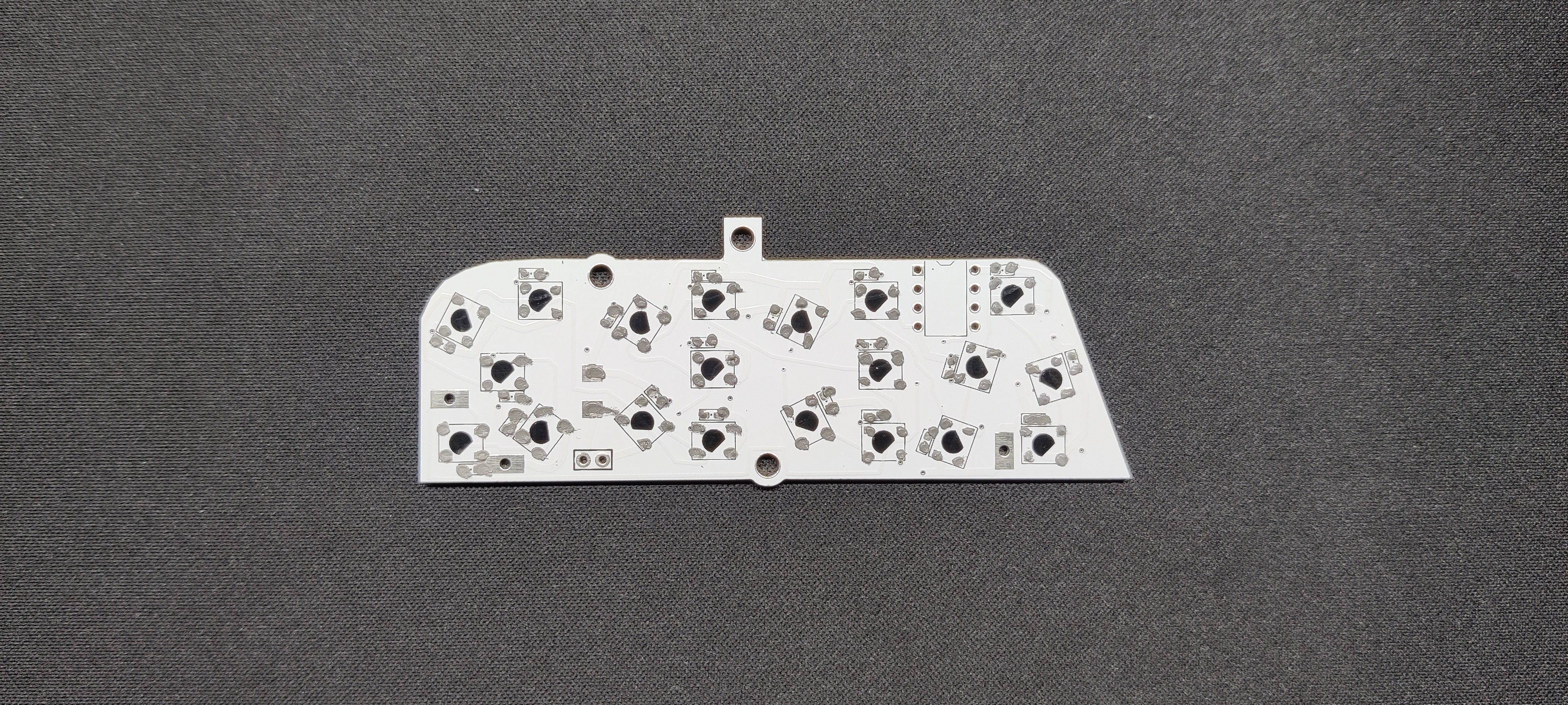
Using a solder paste dispensing needle, we first add solder paste to each component pad, one by one. We're using standard 37/63 solder paste here.
Next, we pick and place all the SMD components in their places on the PCB using an ESD tweezer.
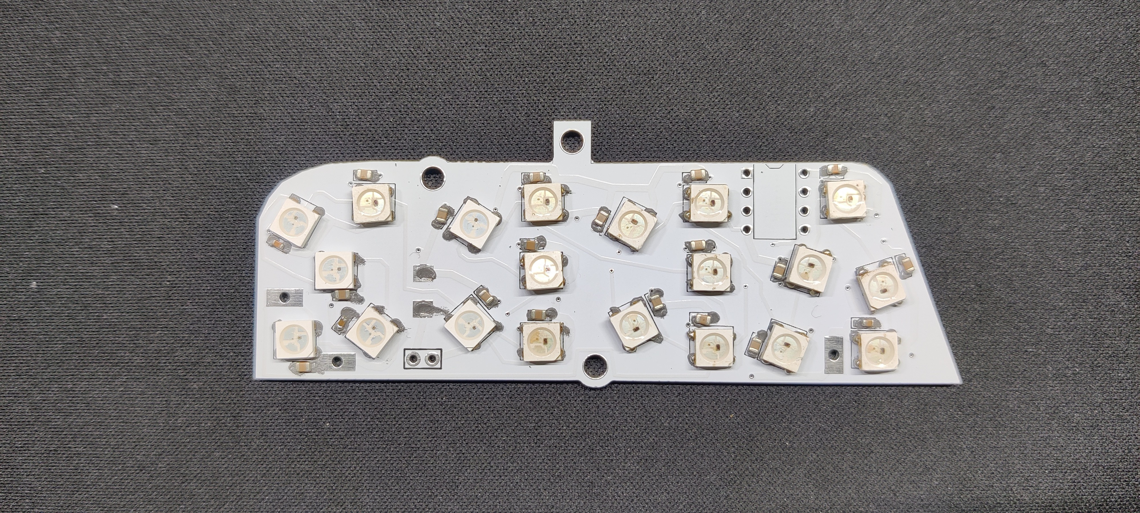
With extreme caution, we lifted the complete circuit board and placed it on the SMT hotplate, which increases the PCB's temperature to the point at which the solder paste melts and all of the components are connected to their pads.
At last, we added the DIP8 socket in its place and used a soldering iron to solder its pads.
2
Adding USB Cable
The positive and negative wires of a USB cable are then connected to the VCC and GND of the LED board circuit after cutting the micro USB end of the cable.
This USB Cable will be the power source of the LED Board.
3
Programming the Attiny85
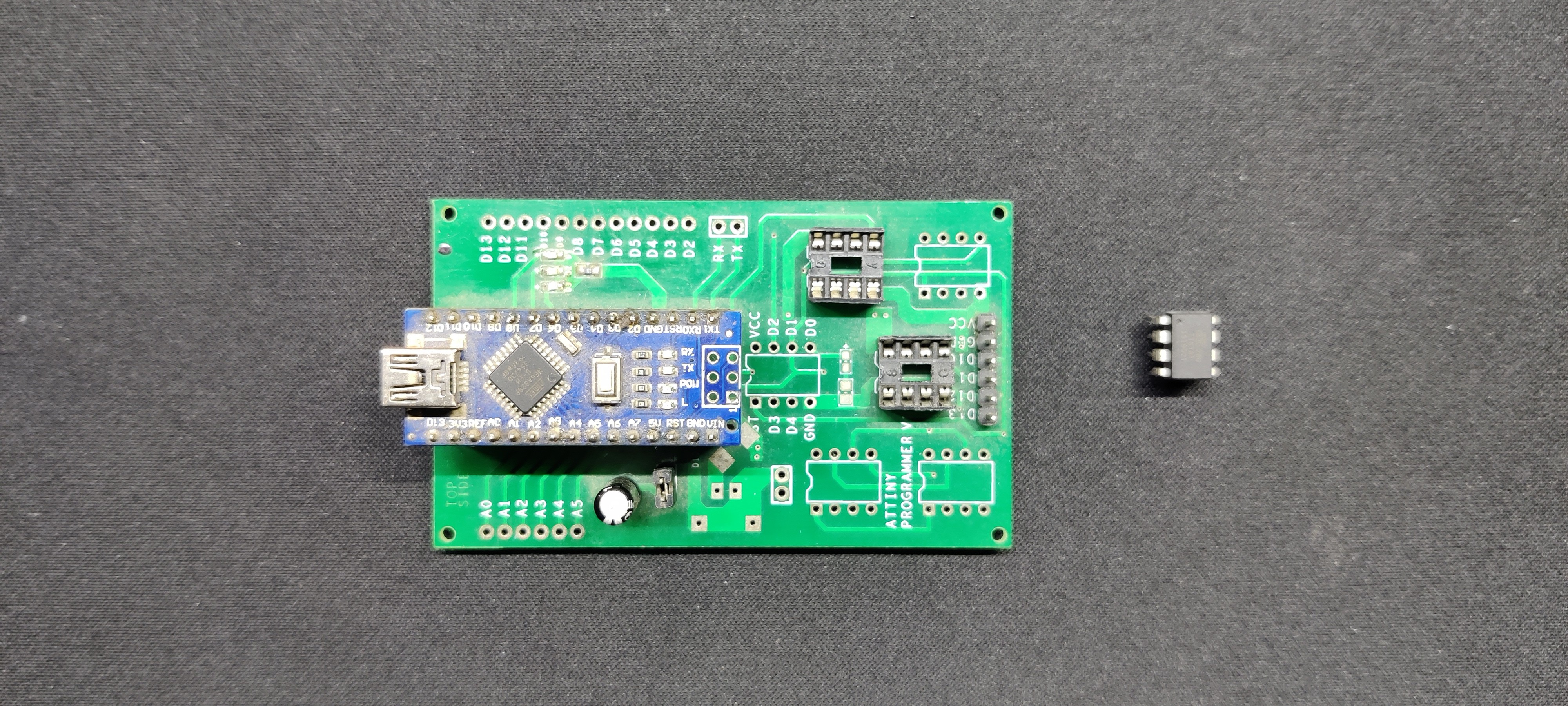
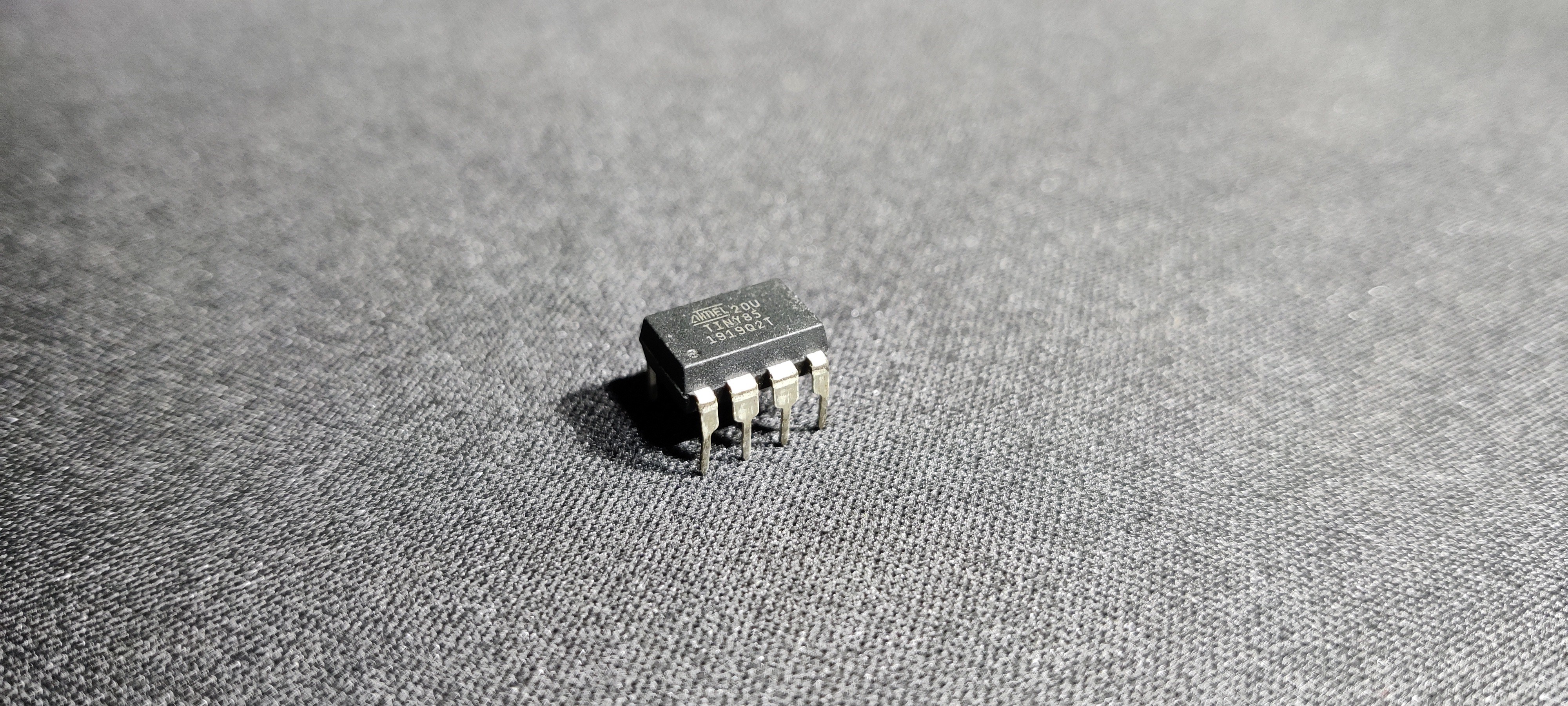
As for the Brain of this project, we used Attiny85 here, which will be programmed using our previously made Arduino as ISP Shield.
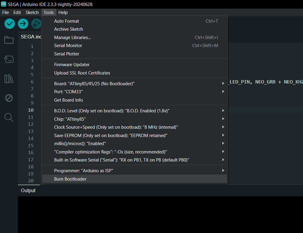
After installing and setting up the core files, we go to tool menu and select the Attiny85 on board. We set the B.O.D to 1.8V and selected the programmer as "Arduino as ISP".
We then burn the bootloader, which takes up to 30 seconds to burn.
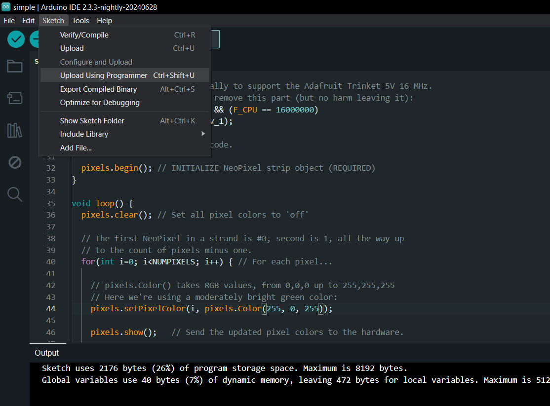
Once the bootloader has been burned, we select "Upload using programmer" from the sketch menu to upload the sketch to the Attiny85. The ISP Flashing Method does not support the regular upload method.
4
Main Code
Here's the main code used in this project, and its a simple one.
At last, we mounted two M2.5 PCB standoffs on the holes provided on the lower LED board circuit by using two M2.5 nuts from the bottom side of the PCB.
Next, we place the top PCB in its position over the PCB standoffs and use M2.5 bolts to secure both PCBs together.
6
RESULT
Here's the result of this small build: a working LED board that looks pretty sick. By following this method of using two PCBs stacked together, one can easily make LED sign boards of anything from name to character.
After finishing this project, we mounted it inside our PC beside the previously made Master Chief Light Board using M3 bolts.
Below are a few art-based PCB projects I did, which you can checkout if interested in this topic.
 Arnov Sharma
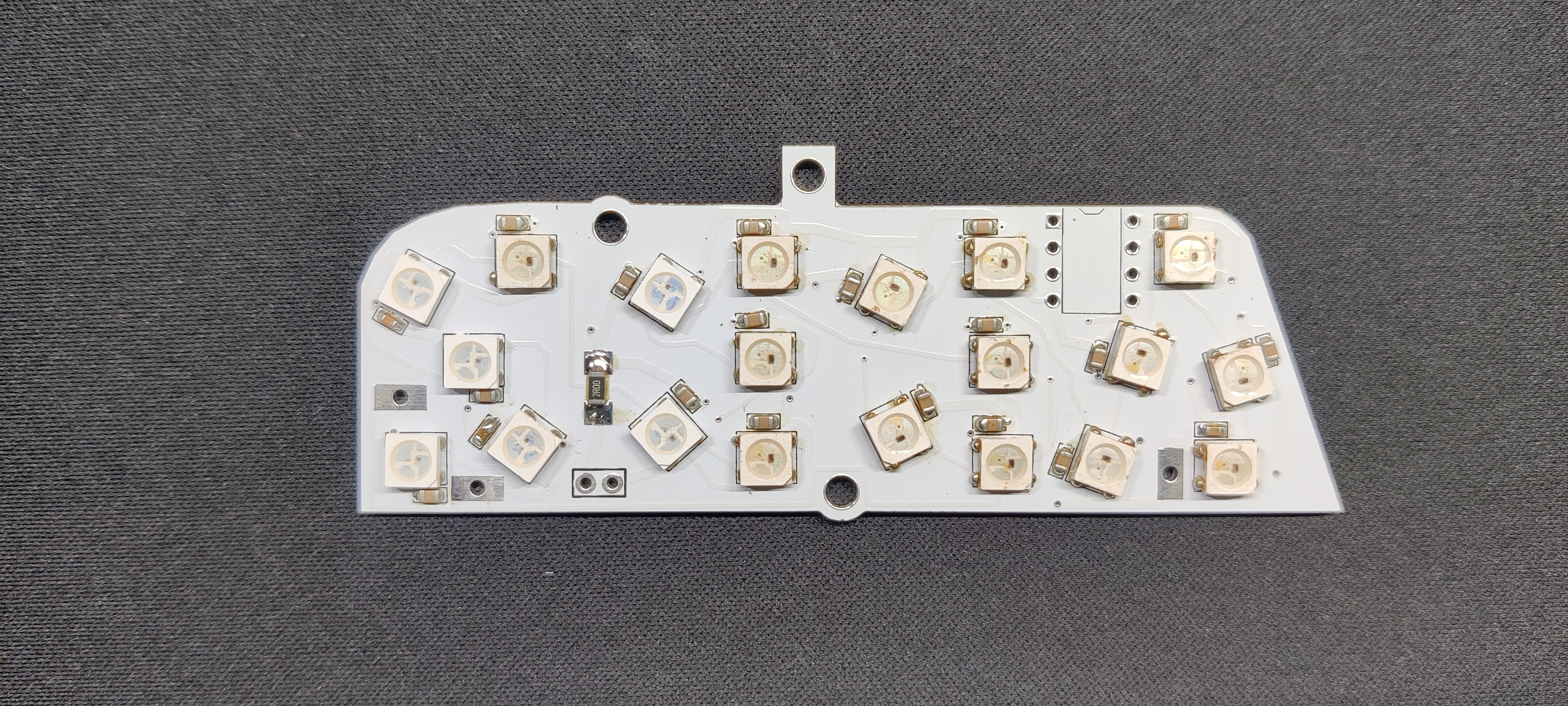
Discussions
Become a Hackaday.io Member
Create an account to leave a comment. Already have an account? Log In.