Overview
The garage door opener remote control stopped working. I decided to replace it with an Android app on my phone. I wrote a little piece of code that runs on a Raspberry PI Pico using MicroPython that opens the door. It communicates with the app using Bluetooth Low Energy (BLE).
I chose the PI Pico because I had one on hand when I started the project. It was cheap so I had bought one to play with previously. It also had BLE capabilities. It didn’t need to be low powered as it would always be plugged in. Also, I wanted the chance to try out programming a microcontroller with Python.
I did not want the opener to have a Wifi or cloud component. It might have been cool to open the garage remotely, but it’s not at all necessary - in fact counterproductive. I only need to operate it when I’m sitting in the driveway.
Materials
DC 1 Channel Optocoupler 3V/3.3V Relay High Level Driver Module Isolated Drive Control Board 3V/3.3V Relay Module for Arduino https://www.amazon.com/gp/product/B07XGZSYJV
Raspberry PI Pico https://www.raspberrypi.com/products/raspberry-pi-pico/
Takeout container to put it in: https://www.amazon.com/YW-YSD-2532-12-Plastic-Soup-Container/dp/B06Y6JWQTD?th=1 I recycled one I already had on hand.
Garage Door Opener
The garage door opener is an older model that has a wired switch near the door as well as the remote control. After a bit of online research and testing, I confirmed that all I needed to do to trigger the door to open or close was to momentarily complete the circuit between the two terminals on the opener.
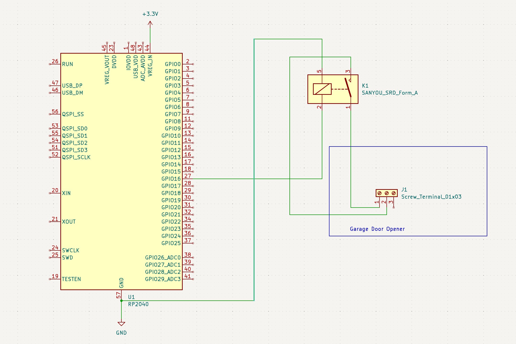
To avoid frying the microcontroller, I used a relay between the GPIO pins on the Pico and the Garage to complete the circuit. As wikipedia describes, a relay is an electrically powered switch.
The opener doesn’t have any logic to know if the door is open or closed. When the switch activates, the garage door opens or closes, or if it’s currently moving, it stops. I’ve never looked at the hardware, but I expect it’s just a question of what direction the motor turns, governed by some limit switches which stop the motor and reverse the direction next time it starts.
Microcontroller Circuit

Connect the Pi Pico to USB for power and connect one terminal of the relay to Pin 16 and the other to ground. Connect the output connectors on the relay to terminals 1 and 2 of the garage opener.
When the GPIO pin is set high, the relay turns on and completes the circuit on the opener side, activating the garage door. It only has to turn on for a short time to start the garage door motor.
Microcontroller code
I’m using the BLE advertising example to do the BLE magic. You can find the code here: https://github.com/micropython/micropython/blob/master/examples/bluetooth/ble_advertising.py
My code sets it up and defines an interrupt callback that is triggered when serial input is received. It just looks for the word “Open” coming in and then calls the routine to open/close the door. See A Note About Security below if this triggers your security intuition.
def start():
led_onboard = Pin("LED", Pin.OUT)
ble = bluetooth.BLE()
p = BLESimplePeripheral(ble)

def on_rx(v):
        print("RX", v)
        if b'DoorOpen' in v:
           OpenDoor()
More
def OpenDoor():
   print("Opening...")
   relayPin = Pin(16, Pin.OUT)
   relayPin.value(0) # make sure it's off
   relayPin.value(1) # turn it on
   time.sleep(.5) # wait a very short time
   relayPin.value(0) #turn it back on
   print("done")
You can find the complete code here.
Packaging
The thing I struggle with the most with these microcontroller projects is how to put them in a finished box. In this case, since it was going to sit in the rafters of my garage, it didn’t have to be pretty.
For this project, I put the relay, Pi Pico, and connecting wires in a well washed plastic takeout container that previously contained green thai curry. I punched a hole in the container to fish the control wires to the garage door...
Read more »
 Ben Brooks
 David S

 Paul Whitaker