 Arnov Sharma
-
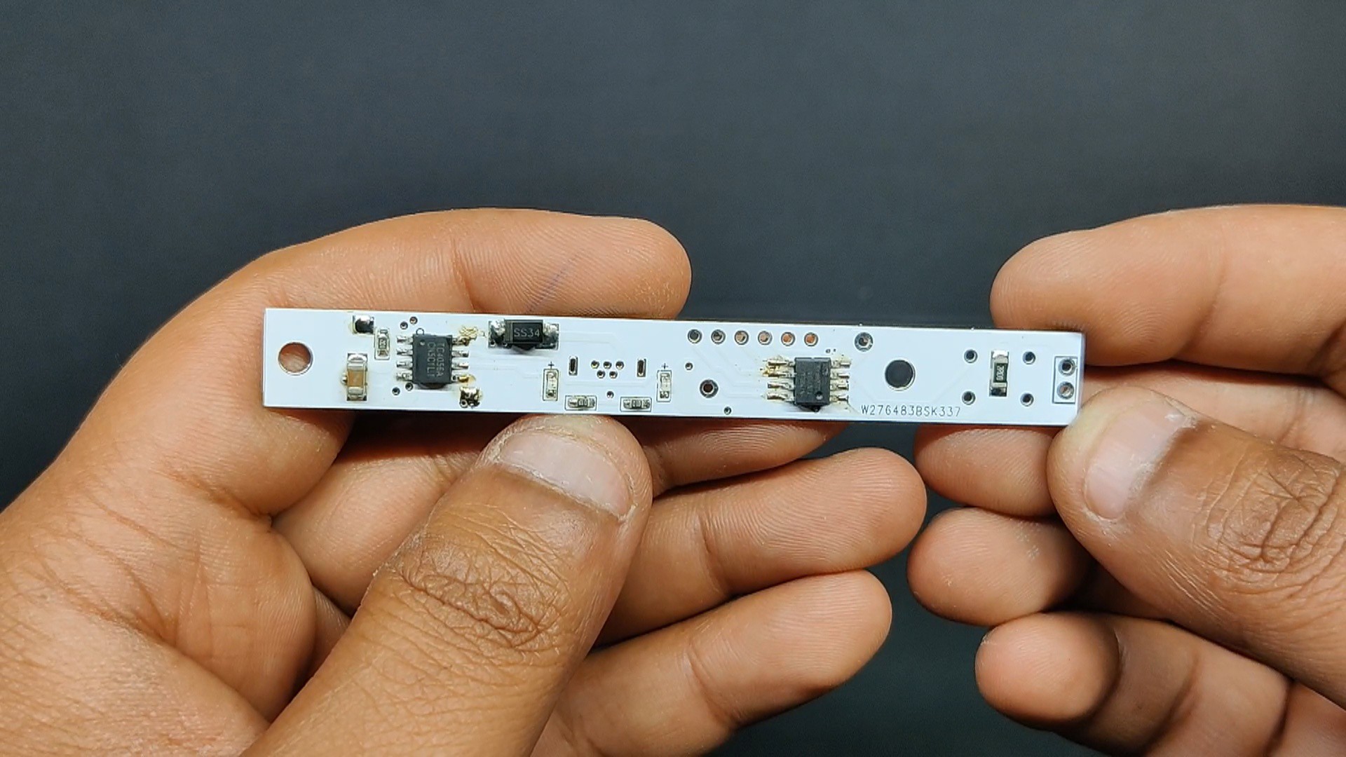
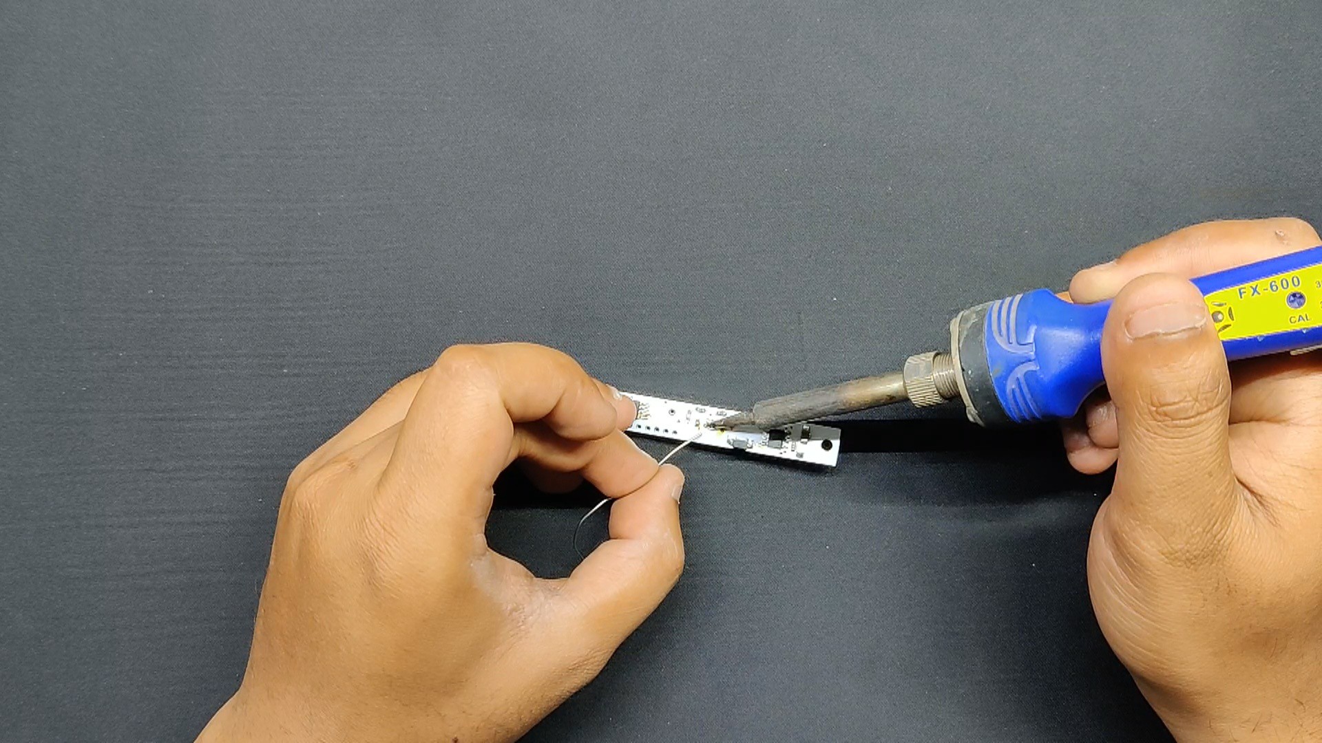
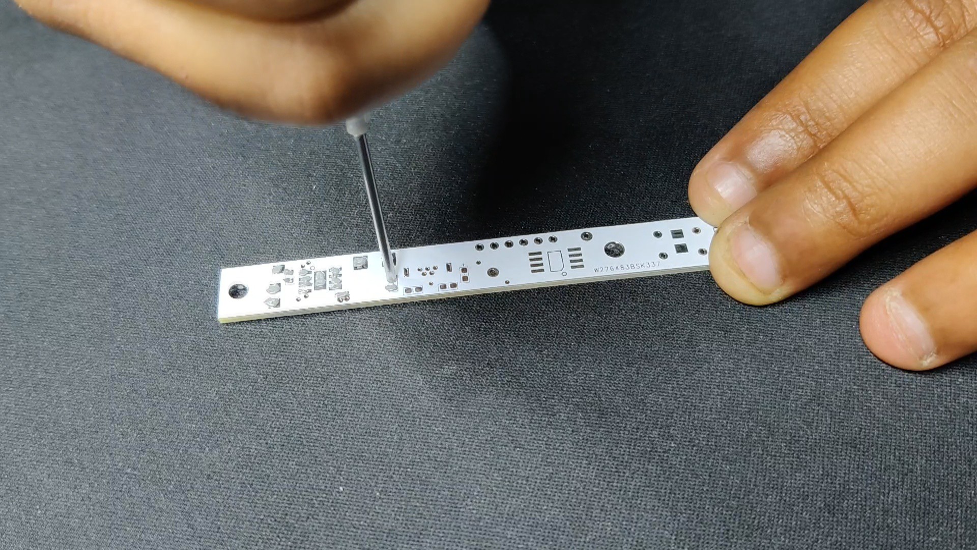
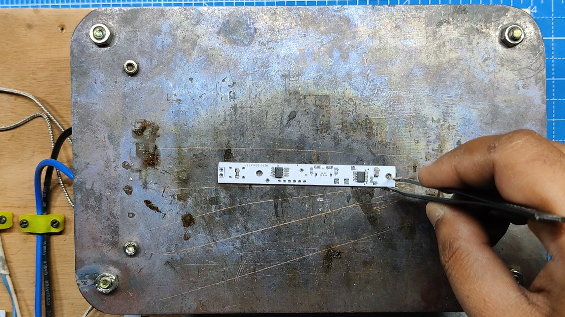
1PCB Assembly Process
![]()
![]()
![]()
![]()
![]()
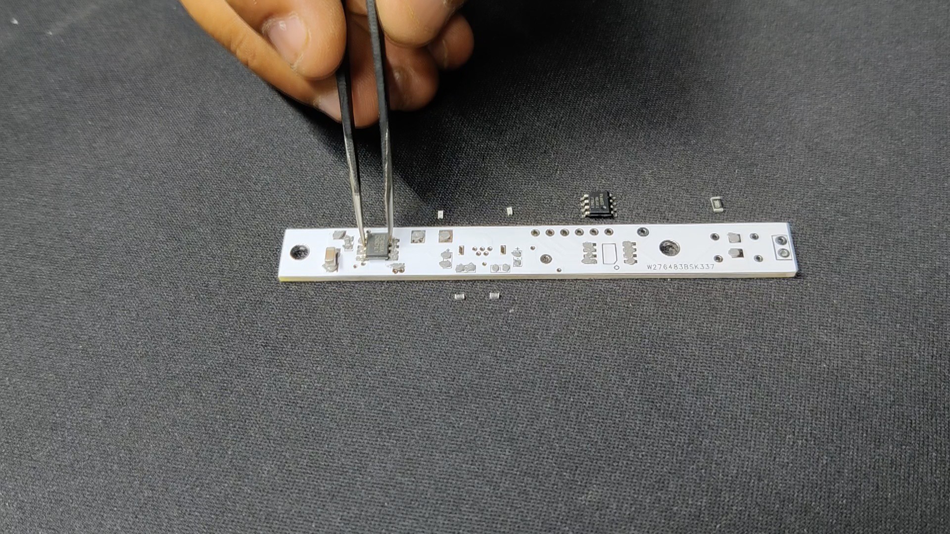
- The PCB assembly process started by first adding solder paste to each component pad using a solder paste dispensing needle.
- Next, we pick and place all the SMD components in their place using an ESD Tweezer.
- We place the circuit on our DIY SMD REFLOW HOTPLATE, which heats the PCB from below up to the solder paste melting temperature, and components are soldered to their pads.
- We then added the vertical USB port and Push Switch to their locations and soldered their pads using a soldering iron.
-
2Power Source: LiPo Cell
![]()
![]()
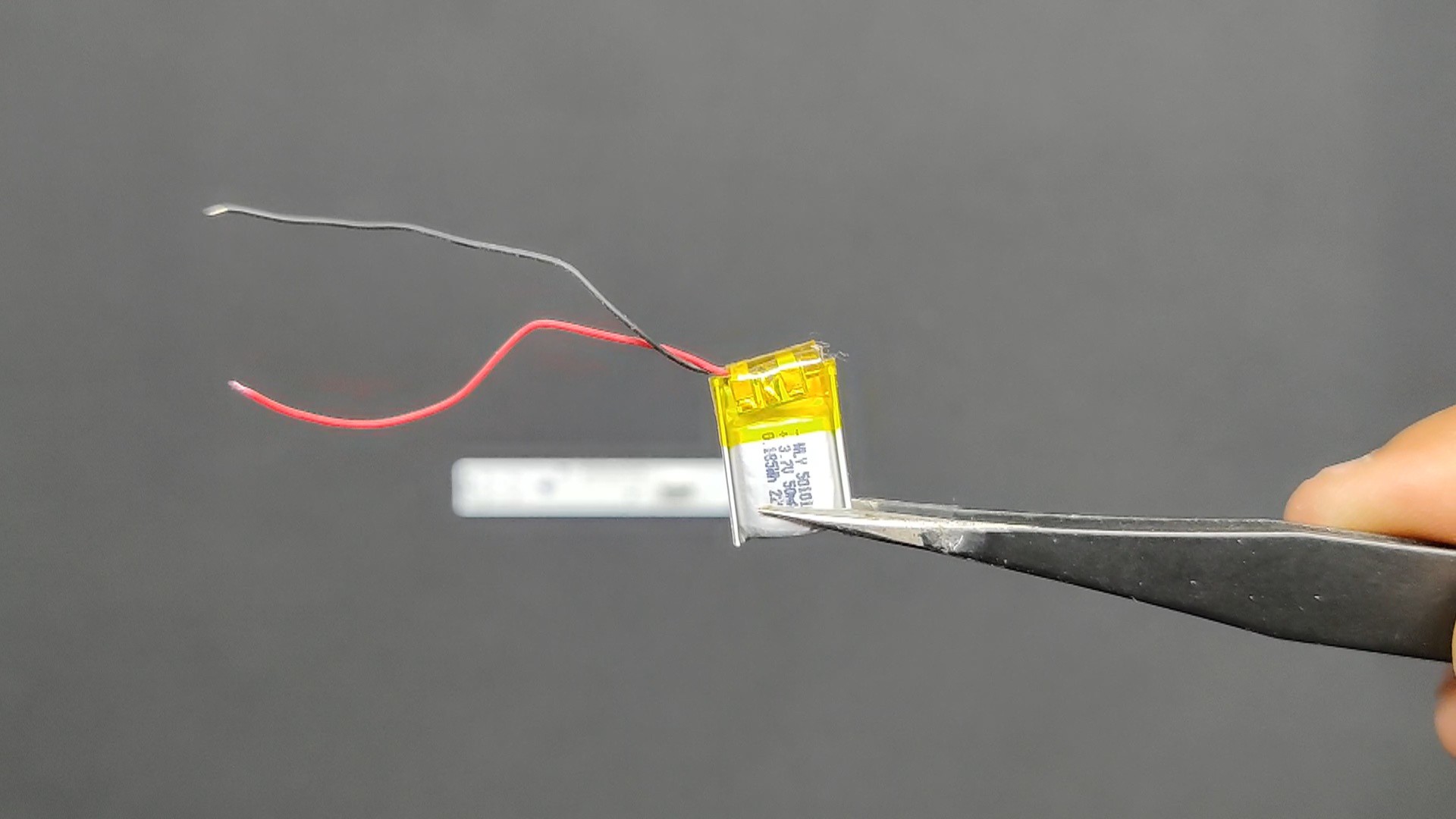
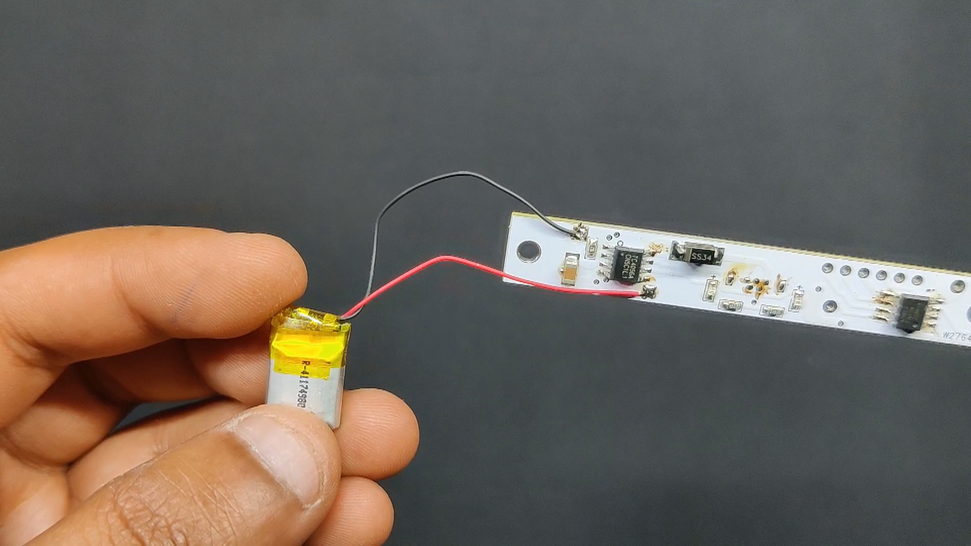
- Once the circuit was finished, we connected the battery connectors of the circuit to the positive and negative terminals of the LiPo cell.
- After that, we plug in the power via the USB port and measure the current drawn—0.23 A—using a USB power meter. As the battery charges, the current it draws will decrease. At the moment, the battery's voltage is 3.8V, and its maximum voltage will be 4.2V.
- The red LED will glow during the charging process; however, the green LED will turn on and the red LED will switch off when the battery reaches 4.2V.
-
3Flashing the Attiny 13A
![]()
![]()
![]()
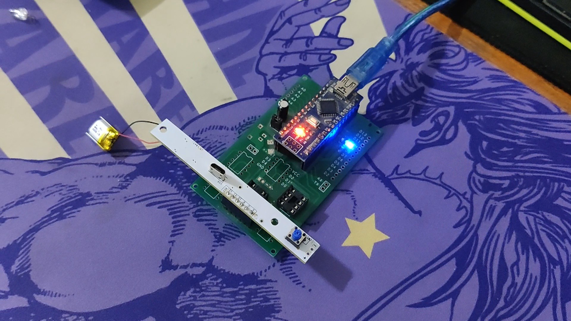
As for the brain of this project, we used Attiny13A here, which will be programmed using our previously made Arduino as an ISP shield.
https://www.hackster.io/Arnov_Sharma_makes/multiple-attiny85-13a-programmer-84adf8
Here, we added the circuit to the programming shield by placing the programming CON6 header pins with the CON6 header pins of the mainboard.
- Next, we install the Attiny13 Core files for Arduino by going to the below link.
https://github.com/MCUdude/MicroCore
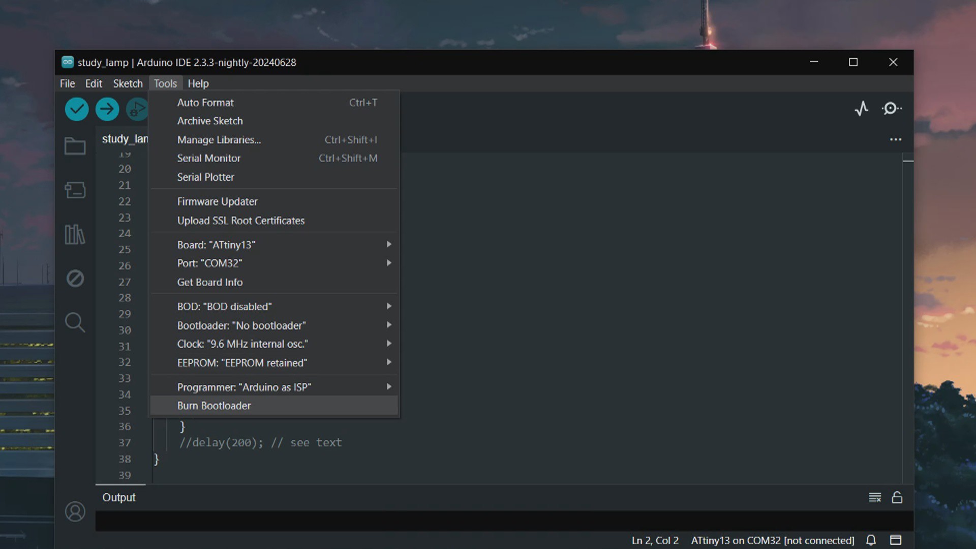
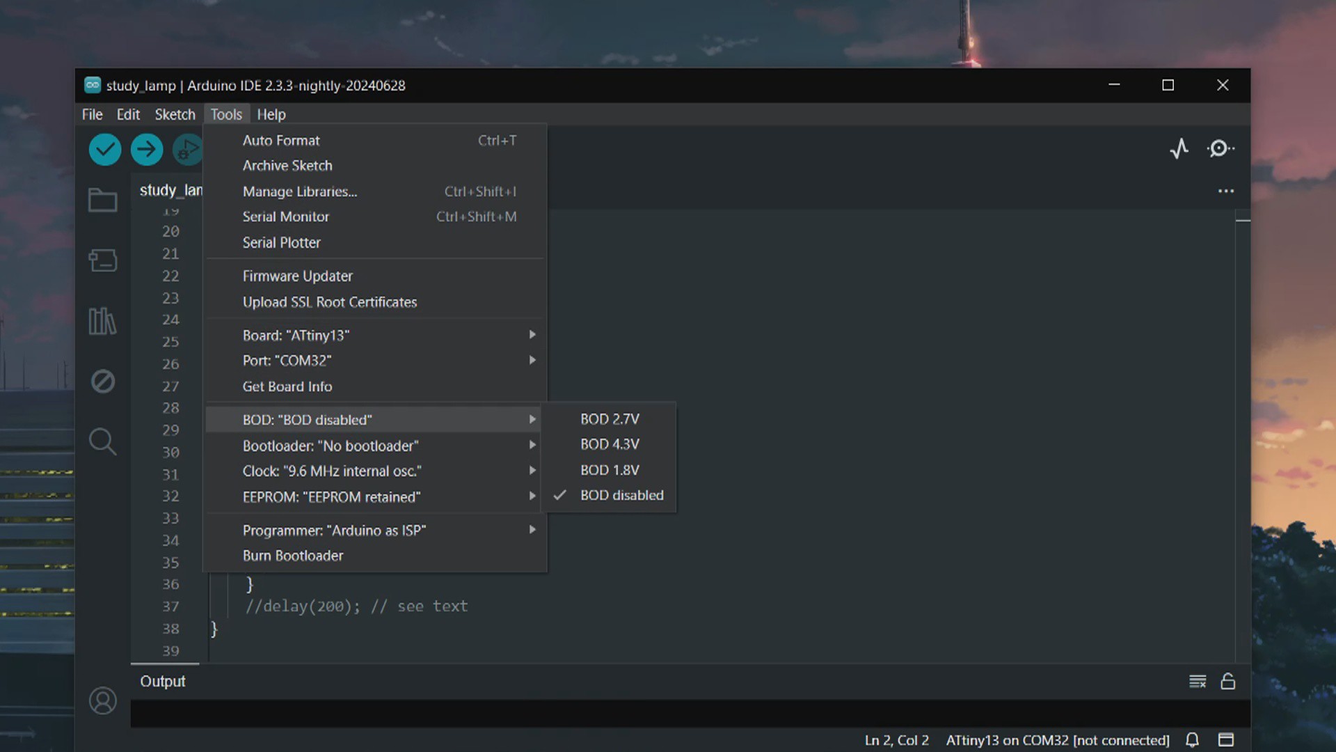
- After installing and setting up the core files, we go to the tool menu and select the Attiny13 on board. We set the B.O.D to 1.8V and selected the programmer as "Arduino as ISP.".
- We then burn the bootloader, which takes up to 30 seconds to burn.
- Once the bootloader has been burned, we select "Upload using programmer" from the sketch menu to upload the sketch to Attiny13. The ISP flashing method does not support the regular upload method.
-
4MAIN CODE
Here's the code used in this project.
const int switchPin = 4; const int lightPin = 0; int lightMode = 1; void setup() { pinMode(lightPin, OUTPUT); pinMode(switchPin, INPUT_PULLUP); digitalWrite(lightPin, LOW); } void loop() { if (digitalRead(switchPin) ==LOW) { lightMode = lightMode + 1; if (lightMode == 4) { lightMode = 1; } } if (lightMode == 1) { digitalWrite(lightPin, 50); delay(500); } else if (lightMode == 2) { analogWrite(lightPin, 250); delay(500); } else if (lightMode == 3) { analogWrite(lightPin, LOW); delay(500); } //delay(200); // see text } -
5Wand Assembly Process
![]()
![]()
![]()
![]()
![]()
![]()
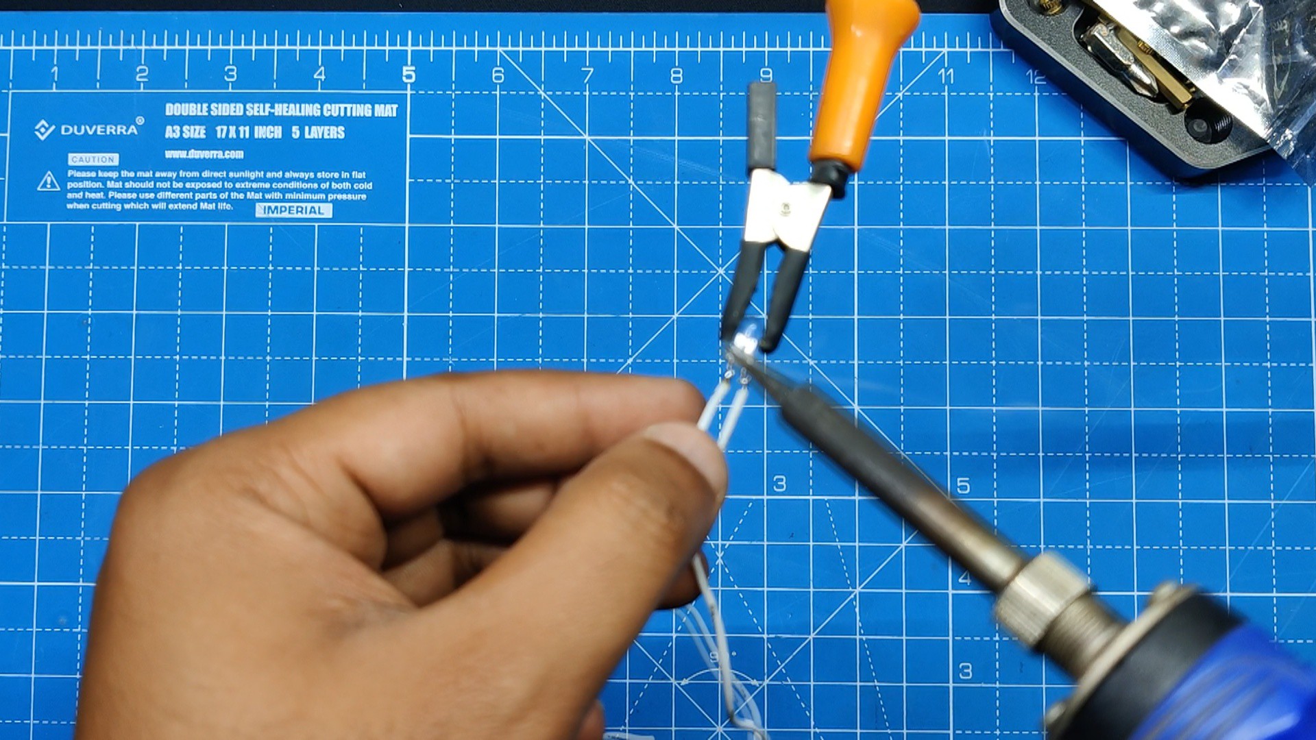
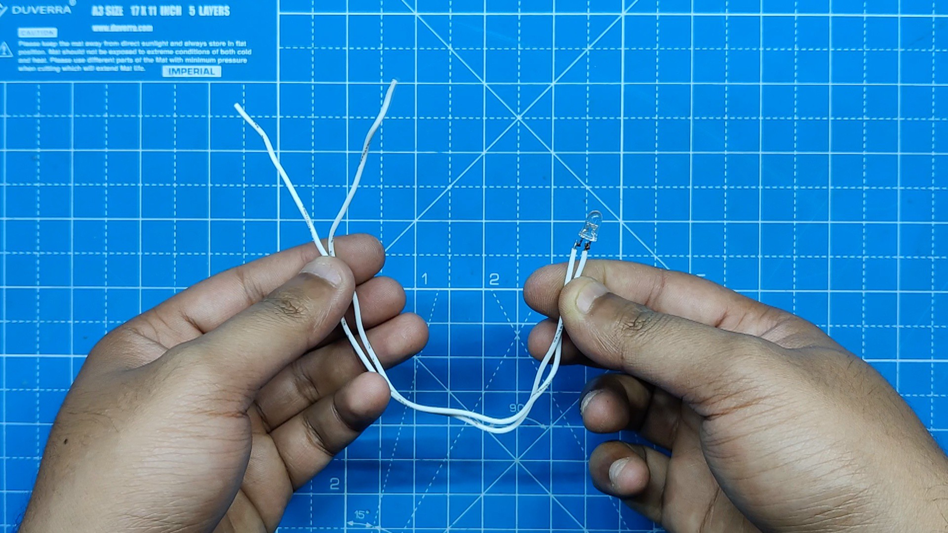
- The first step in the main assembly procedure is to attach two 190mm wires to the 5mm LED's positive and negative terminals.
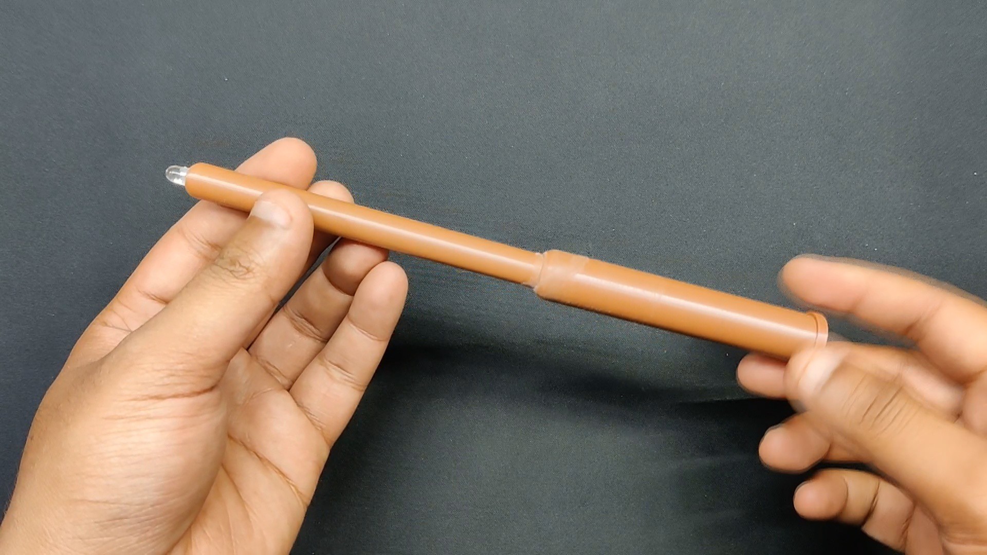
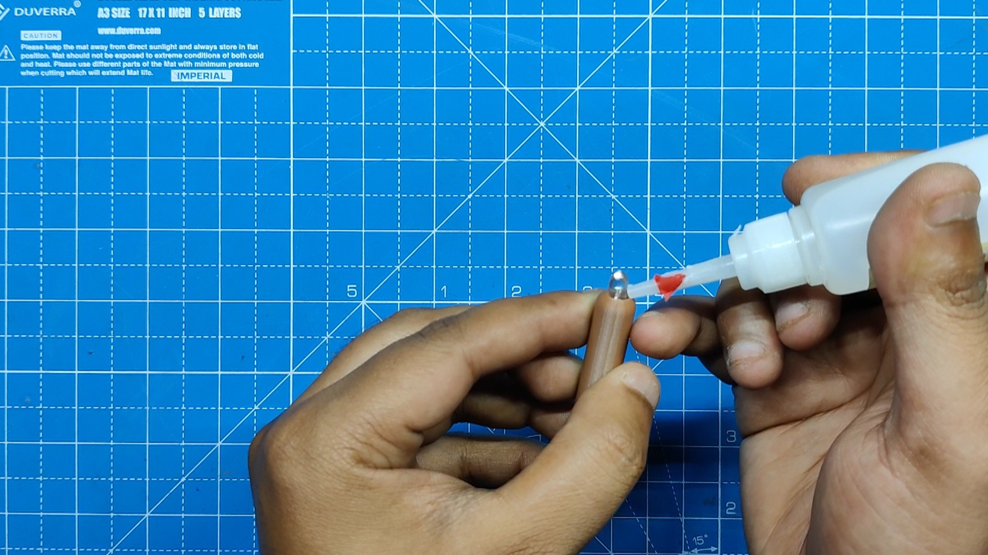
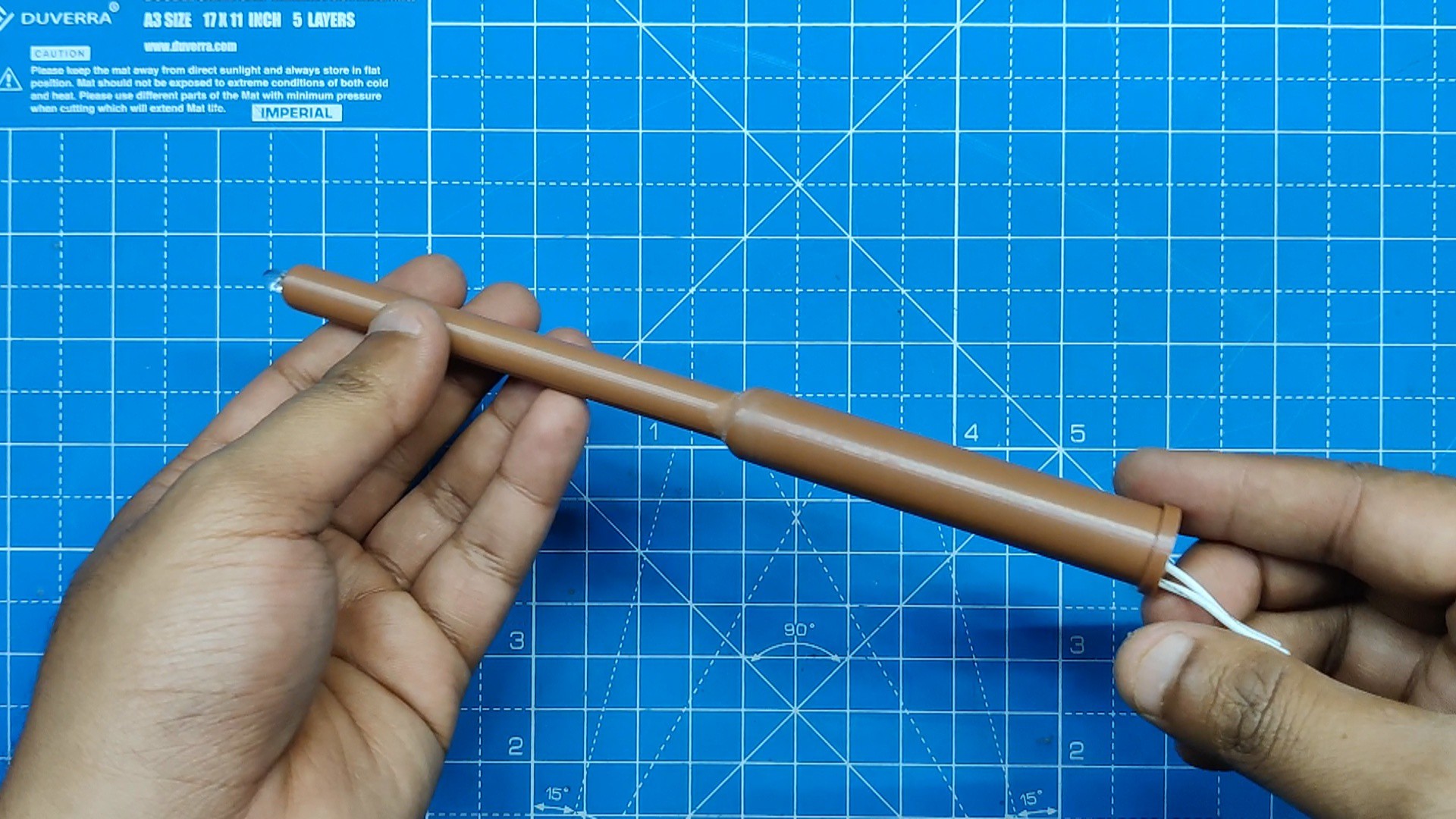
- The 5mm LED was then pushed inside the shaft assembly, causing the LED to pop out from the shaft's end.
- With the help of superglue, we secure the LED in its place.
- We now connect the LED terminals to the load terminals, or CON2 pads, which are on the main PCB.
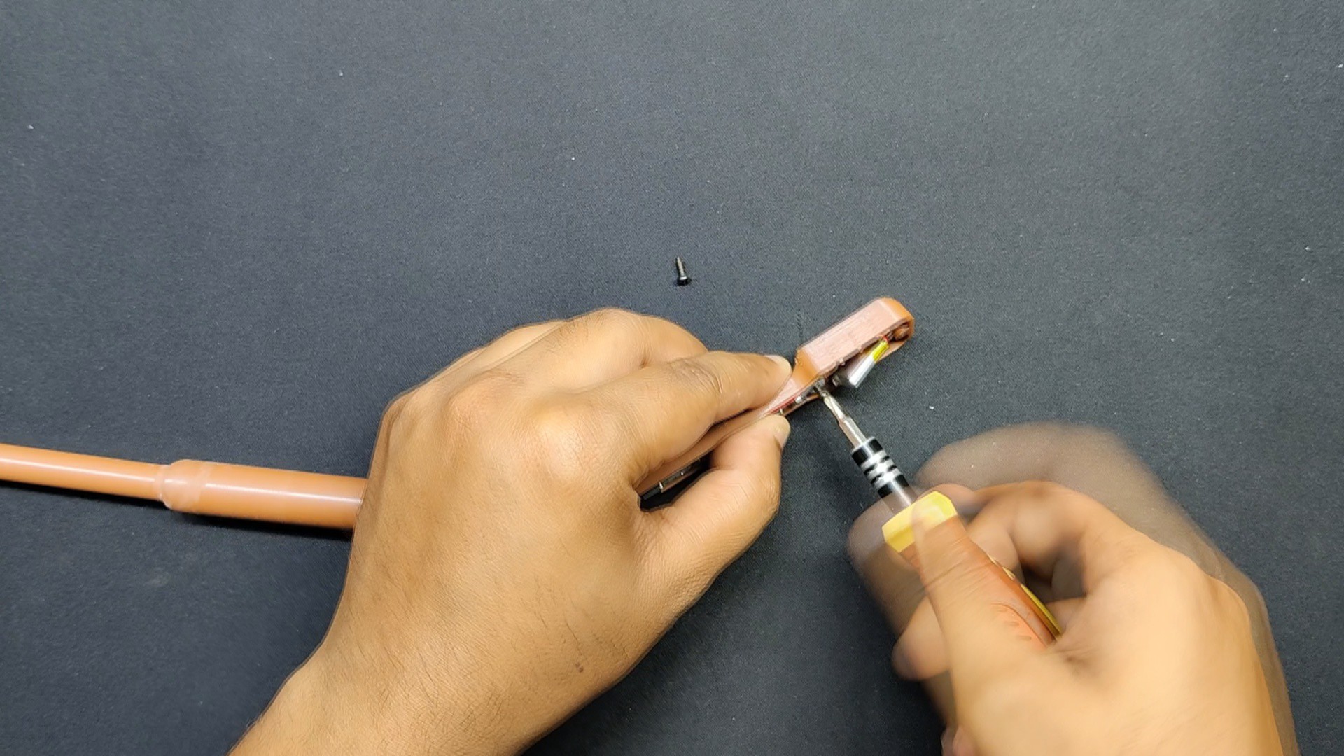
- The circuit is then placed on top of the designated screw bosses, and the battery is then placed in its proper position on the other end of the handle.
- In order to secure the circuit in place, we join it with the handle portion screw bosses using two M2 screws.
- The shaft assembly is then placed on the handle part, and the shaft's position is held in place by the other handle part. These two components will ensure that the shaft assembly remains in place.
- We use five M2 screws to mount both handle parts together.
The assembly is now complete.
-
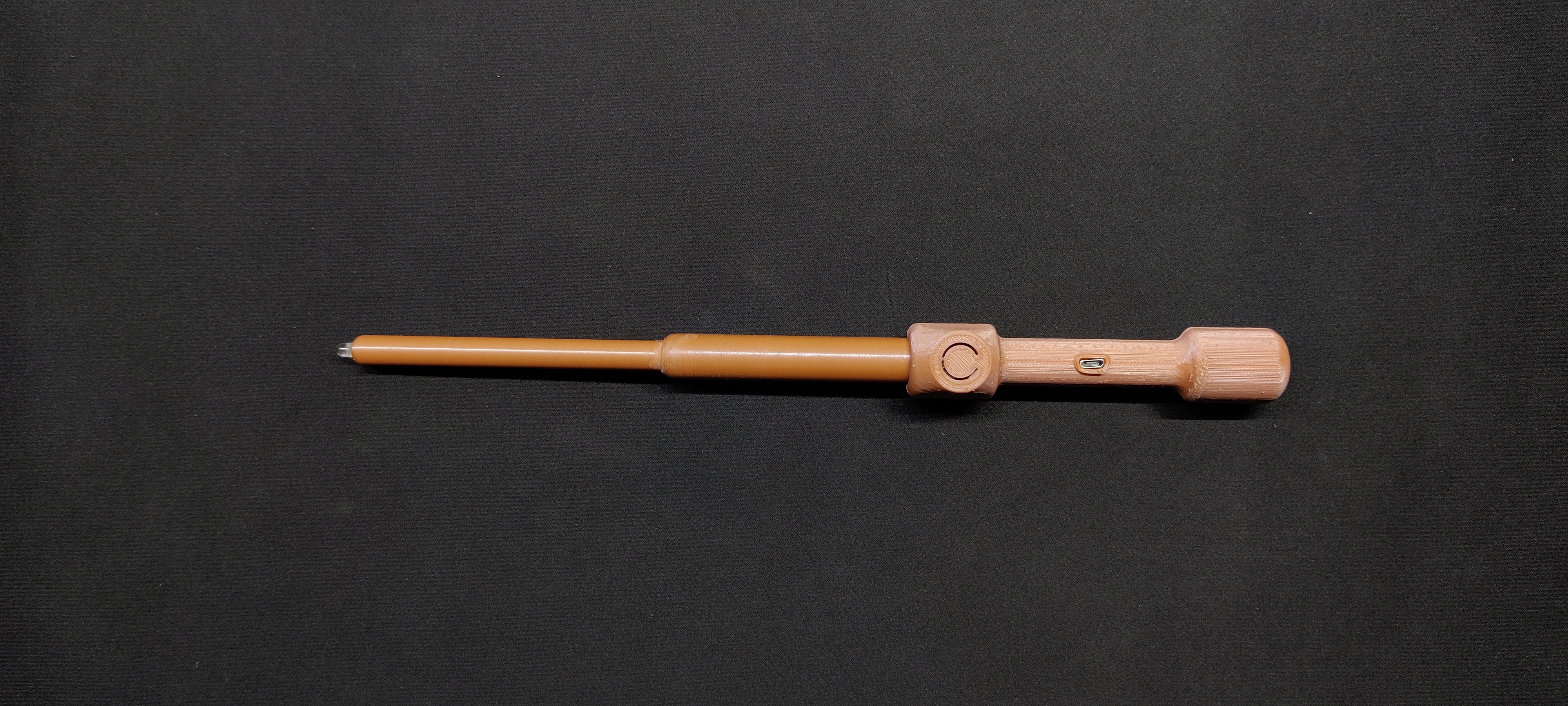
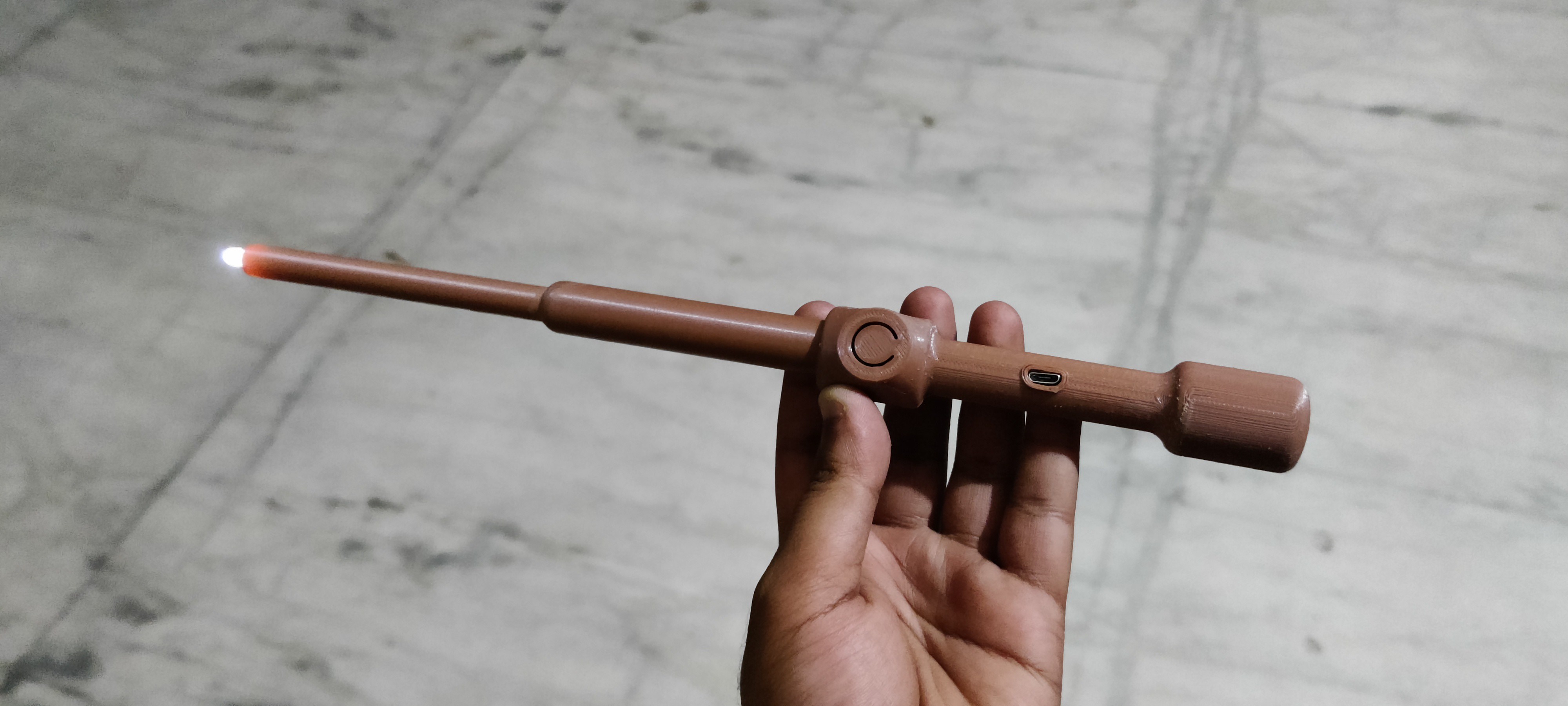
6RESULT
![]()
![]()
Here's the result of this magical build: a working Wand-Flashlight that works.
The light is controlled by a switch on the grip of the wand. Here, a white, 5mm Everlight LED with a 15-degree viewing angle provides the light; in the past, torches used these LEDs.
Although this wand cannot be used for magic, the Attiny13 that is being used here is doing a wonderful job of driving the LED.
This Wand-Flashlight can be used outside without any issues as a test. Although it is not very bright, the light works. In the upcoming version, a high power SMD LED will replace the 5mm LED to improve lighting.
Overall, this project was a success, but I will be preparing version 2 to improve the light intensity.
In addition, we appreciate PCBWAY's support of this project. Visit them for a variety of PCB-related services, such as stencil and PCB assembly services, as well as 3D printing services.
Thanks for reaching this far and i will be back with a new project pretty soon.
Peace.
Discussions
Become a Hackaday.io Member
Create an account to leave a comment. Already have an account? Log In.