 Supplyframe DesignLab
-
1Overview
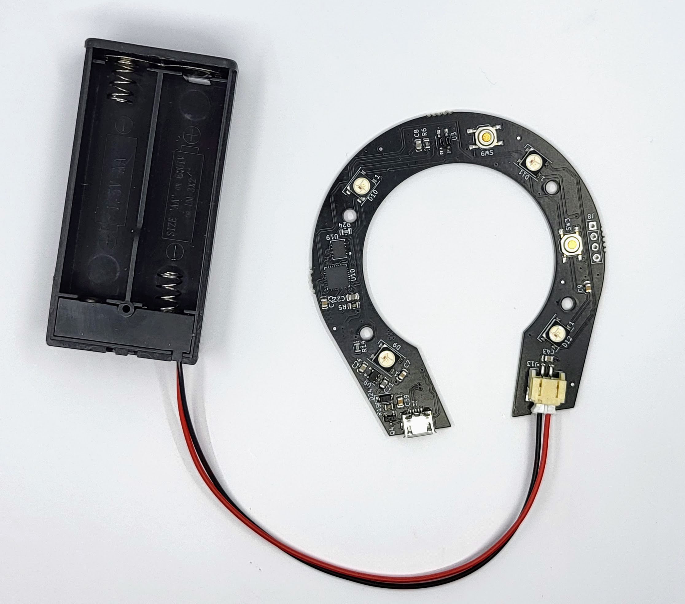
The project has a few essential components:
- PCBA,
- Battery holder
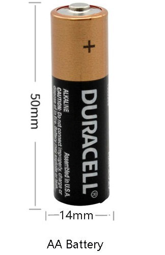
- Batteries, and
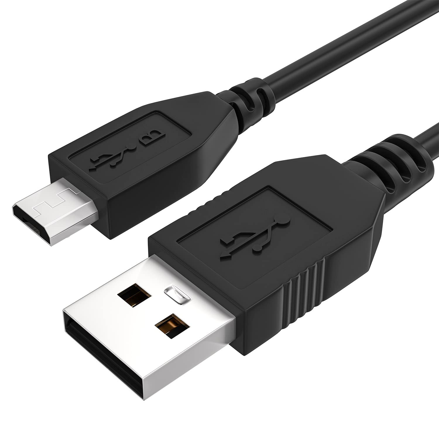
- Micro USB cable.

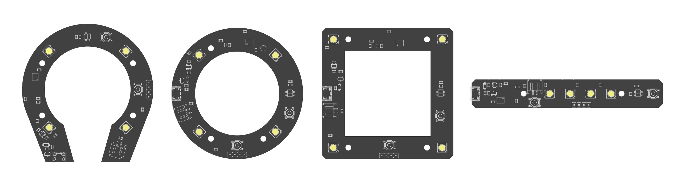
As mentioned before, all the PCBA shapes (square, circle, line, horseshoe) share the exact same circuit and BOM (Bill of Materials). Please choose the one that better fits your design concept.
When you design your lamp, you will decide where you want to keep the batteries. Just keep in mind that they should be easily accessible to replace.
-
2PCBA
You could think of the Printed Circuit Board Assembly (PCBA) as the "grounds" where a "city" is built. Electricity flows through the PCB to the different components, and each one does something different and generally indispensable for your product to work properly. While you do not need to understand how each component works, it is important to have a general understanding of the more relevant ones, particularly for your project.
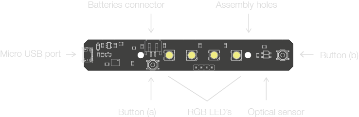
Here is a quick overview, before we go into more detail:
- Four independently addressable RGB LED's,
- Two buttons,
- One micro-USB port,
- One battery connector,
- One optical sensor
- Assembly holes.
Assembly holes and precise dimensions can be found in the 2D vector file, and in the 3D STEP files.
-
3LED's
We are using independently addressable RGB LED's. Quite a mouthful, but every word is important there.
- RGB means that they can cast Red, Green, Blue light, and everything in between.
- Independently addressable means that each one can be operated separately, through code. Each LED has its unique "number".
-
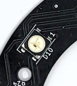
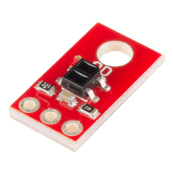
4Sensor
Each lamp comes with one Mini Object Sensor. Can you find it in each board?
This sensor can detect motion or objects near it. It has a range of 5 mm. If you want to learn more about it, you can check outSparkfun's breakout board listing.
Image credit: Sparkfun.com
-
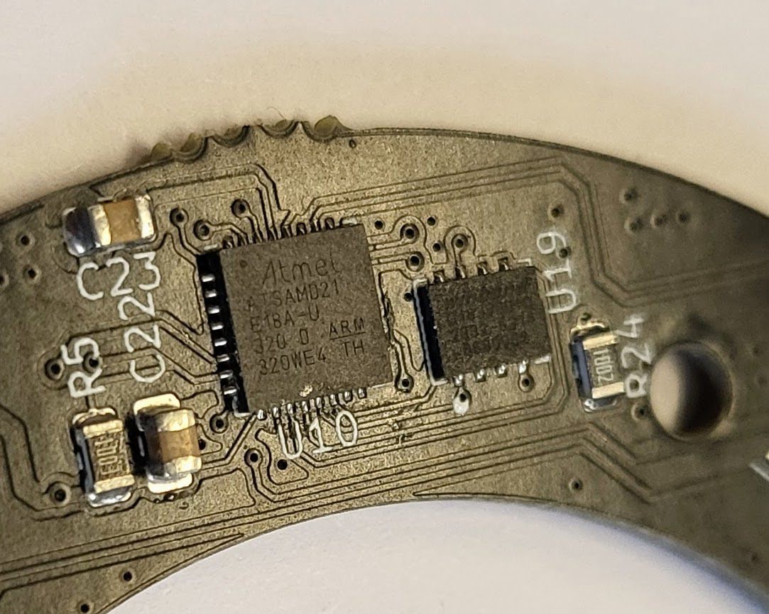
5The microcontroller - ATSAMD21E18
The PCB lamp used in this workshop is powered by a Microchip's ATSAMD21E18 microcontroller.
It is a low-power, high-performance Microchip's ARM® Cortex®-M0+ based Flash microcontroller. At industry level, it is used for home automation, consumer, metering, and industrial applications.
Some of its features are:
- 256KB of flash and 32KB of SRAM, up to 48MHz operating frequency
- Four serial communication modules (SERCOM) configurable as UART/USART, SPI or I2C,
- Three 16-bit timer/counters,
- 32-bit Real-Time Clock and calendar,
- 18 PWM channels, one 14-channel 12-bit ADC, one 10-bit DAC
- Full Speed USB Device and embedded Host
- 1.62V to 3.63V power supply
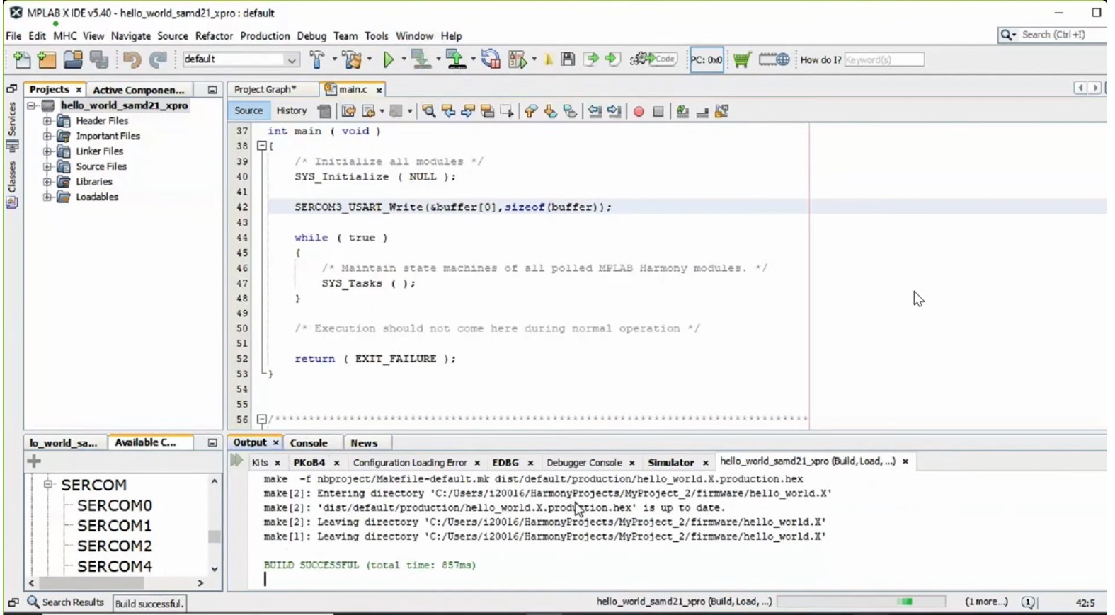
Microcontrollers can be programmed with a variety of Integrated Development Environments (IDE). However, when they are programmed for real mass-manufacturing applications, microcontrollers need to be as efficient as possible. Microchip has its own IDE called MPLAB, which is really powerful. Learning how to use it goes beyond the scope of the workshop, so we will not be using it for now.
-
6Product Design Inspiration
Here are the four shapes. These LED's can be controlled with code, and activated by the optical sensor, or a button. They can be used as a lamp, or a podium, an indicator, an alarm... you have the power now! What will you design?
-
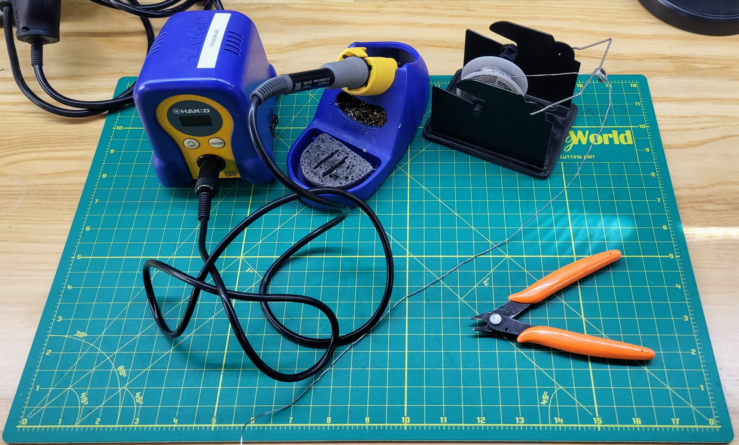
7Recommended tools for the workshop
We do not need a lot to get started!
- Mac or PC laptop
- USB A to micro-USB cable
- Screwdriver
- Lamp body or enclosure
-
8Coding with CircuitPython (Installing Mu)
We will be coding this lamp using CircuitPython.
CircuitPython is a subset of Python (the programming language), that was designed to simplify experimenting and learning to code microcontroller boards.
Programming languages need editors. And for this particular board and workshop, we will be using the Python Editor MU.
Please make sure to have installed Mu in your computer before the workshop.
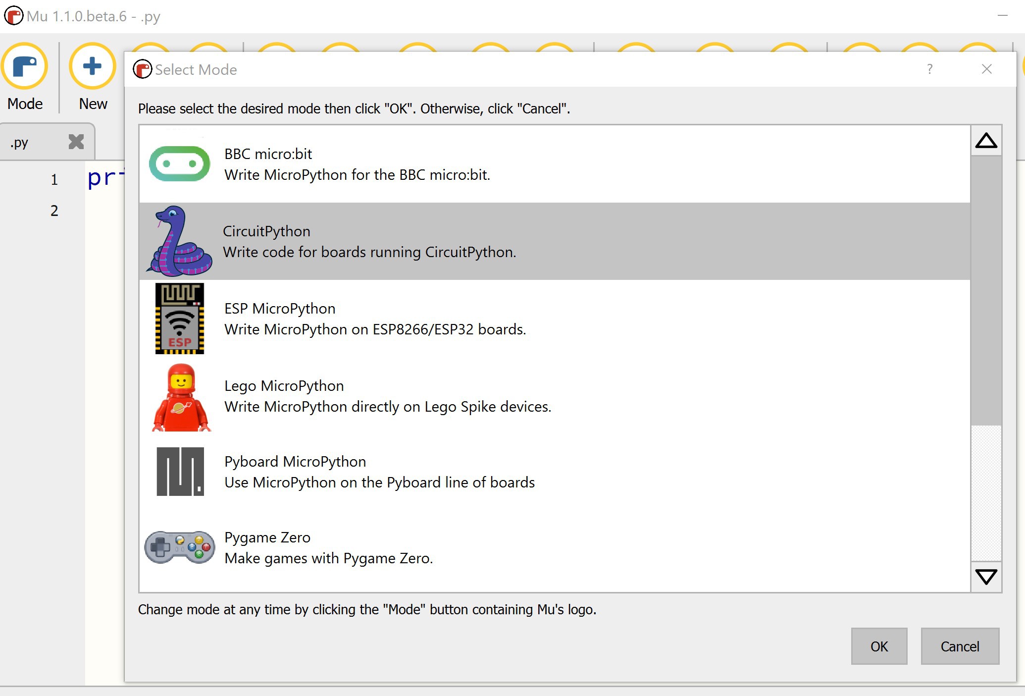
Once you have Mu installed, click on "Mode", and from the Select Mode list, select "CircuitPython".
Just to make things easier, close Mu. Now, plug your lamp to your computer via USB. Once it is connected, open Mu again, and it will detect your lamp automatically (take a look at the bottom right corner by the gear).
-
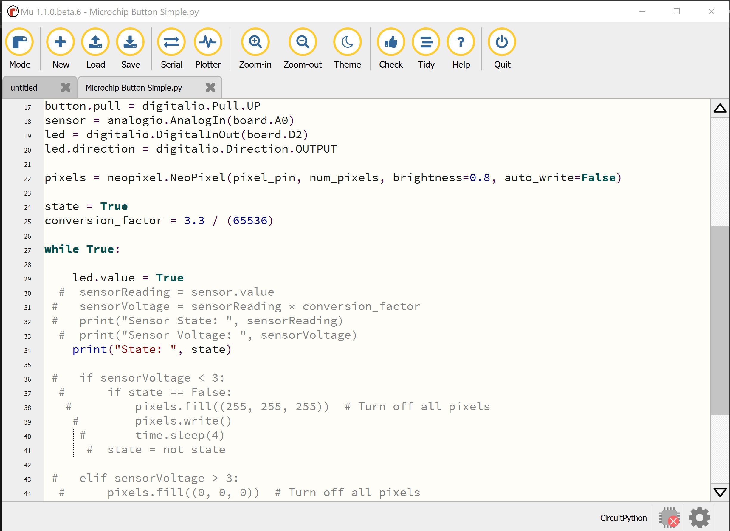
9Coding with CircuitPython (Editing Code in Mu)
- Open Mu and press the snake icon in the upper left for “Mode” and select Circuit Python.
- Connect the board to your computer with a micro-USB cable.
- Code will run automatically if the board is connected to USB even if there is no code written in Mu. If you click the serial monitor button, you can see the sensor reading for the code currently running. Be mindful that the serial monitor will slow down your computer while open.
- Click the “Load” button to load the example code “DL_lamp_MCH_v1.0” or edit other code. These should be .py files. You can create another empty page by pressing the “New” button.
- Once you have edited the code, click the “Save” button. Be aware that this will save over the file you are editing that you loaded into Mu from a .py file. There is no “save as” so make sure to make a duplicate of your code if you want to go back to a previous version.
- Once you have saved your code, rename the file to “code.” Naming the code “code” is necessary for the board to know which code to run on start up as multiple code can be stored on the device.
- Now that you have renamed it to “code”, drag and drop the file onto the device. It should appear on your computer as a USB device called CIRCUITPY. You will be prompted with a message asking if you would like to replace the current file on the device. Select “YES”.
- Once saved to the device, the code should run automatically.
PCB Lamp Workshop - Microchip Edition
Components and instructions to create your own touch-activated lamp, and learn about product design, hardware and firmware.

Discussions
Become a Hackaday.io Member
Create an account to leave a comment. Already have an account? Log In.