Close
0%
0%

The MidBerry HB1

HB stands for "Hookers and Blackjack"

Similar projects worth following
Logs detailing the design and (hopefully) build of an infinitely upgradable Blackberry-esque telecom device with user defined tech

I hate smartphones. They're designed to be disposable, fragile, obtrusive, addictive, and penetrative. The modern ones are so obviously a surveillance device and a money grab I just hate having one on me. However, access to data for navigation and more common things like text and voice is somewhat necessary for the traveling I do. To both solve this social problem I'm experiencing and to improve my hardware and software skills I've decided I'm going to build myself a "midphone," which is in between a dumbphone and a smartphone. The device takes cues from the Blackberry Q20 device, which is though of as one of the best devices produced in the early 21st century, but the similarities end there. The wishlist for the device:

1) all components need to be easy to obtain, work with, repair, and replace. Nothing proprietary.

2) No touch screens, as their interface is power hungry and unnecessary most of the time.

3) Device should be complex enough to handle a Linux distro

4) Device will include some GPIO ports a la the Flipper Zero for add-ons

5) Physical switches capable of hard-cutting power on comm modules (LTE, WiFi, GPS, LoRA)

6) Optional: include LoRa capability on board

IB_Q20.zip

Contains KiCAD files for the ItsyBitsy 32U4 3.3V 8MHz to Q20 adapter PCB

Zip Archive - 196.41 kB - 09/08/2024 at 12:13

Download

Q20AdapterPCB.zip

Contains KiCAD files for Q20 Adapter PCB

Zip Archive - 21.87 kB - 07/21/2024 at 16:45

Download

View all 11 components

  • Design #10: Side Projects and Revamps

    janusprotocol10/13/2024 at 01:37 1 comment

    After playing with an LCD screen for weeks, I realize that my lack of C++ experience is really hindering any sort of advancement in this sphere. It's a much lower level language than Python, which is the only computer language I speak. I'm limited limited by this shortcoming, so I've decided to whip up a side project or two with the explicit with the goal of learning how to speak C++ while simultaneously doing something cool. I'll be designing a module for the Flipper Zero I'm calling the Squeaker, an amateur radio GPIO add-on that will allow for monitoring and, hopefully, transmitting of the two-meter and 70-centimeter amateur radio bands.

    On the actual project side, I've decided to move away from the original Zero 2W form factor boards that inspired this project to the beefier Compute Module 4 (CM4) form factor boards, specifically the Orange PI CM4 module. Instead of worrying about which pins have been exposed, how they're exposed, removing unnecessary USB ports, etc that I'd have to content with, I can design a motherboard that the CM4 will plug into, thus I can route whatever I want wherever I want without issue. As I've already figured out how to deal with Hirose B2B connectors during the Keyboard Project, I'm certain I can get these adapters figured out. Another benefit of using the CM4 is that it can directly drive LCDs via a 2-lane and a 4-lane MIPI DSI channel, thus simplifying the end system; just wire a connector so that it jives with the LCD and you're good! Much simpler, as displays are one of the few unstandardized modern parts I've run into. I dunno what that's about but it definitely sucks to find out that these displays you bought are not very cross-compatible!

    The HB1 is looking like it will contain the following: a display, the Q20 keyboard and associated subprocessor, the SIM7600G-H to provide 4G/LTE and GPS, a GPIO header similar to the Flipper Zero but with better port selection, some general purpose well rounded camera sensor, and maybe a couple of radio receivers/transceivers, depending on how much space I have in the case. I'll begin sketching up what that looks like once the OPi CM4 arrives and I get some  boards made to test an exploded version of my design.

  • Design 9: Success!

    janusprotocol09/24/2024 at 22:00 0 comments

    After weeks of work I f

    Well piss, here I thought I would be clever and write an intro ON the working keyboard, but it seems I must've torn a connector or something, as a whole collection of letters I mapped just last night are no longer sending signals to the MCU. Oh well, I'm just thrilled that I now have a keymap that I know works and the confidence that I can actually engineer circuits.

    Rewind to Friday: I've been on-and-off trying different ways to get QMK firmware onto the IB 32U4 8 MHz 3.3 V board, to no avail. I thought I was getting somewhere using AVRDUDESS, but when I tried to move the window over it crashed and bricked the chip. Arduino IDE cannot write to it anymore, so I may have borked the bootloader. I'll have to investigate repairing it one day, though I doubt it's usefulness as the backpack is soldered on tight. I recently discovered that the lead-free solder I have has a pretty high melting temp, so that backpack board I designed is on there tight.

    In any event, I was at a loss as to what to do. I tried to wire up an ATMega34U4 I had on an adapter board, but that didn't seem to get me anywhere. I thought about just calling it quits when I realized that I had four brand new Raspberry Pi Pico 2 boards I had impulse bought when I heard how scarce they were becoming, and I mean $5 a piece is like laughable for this hobby. Anyway, as I read into them, I had somehow missed the fact that you can program them in Python?! Why was I fucking around with C++ this whole time when I could've been coding in a language I already spoke? Gah!

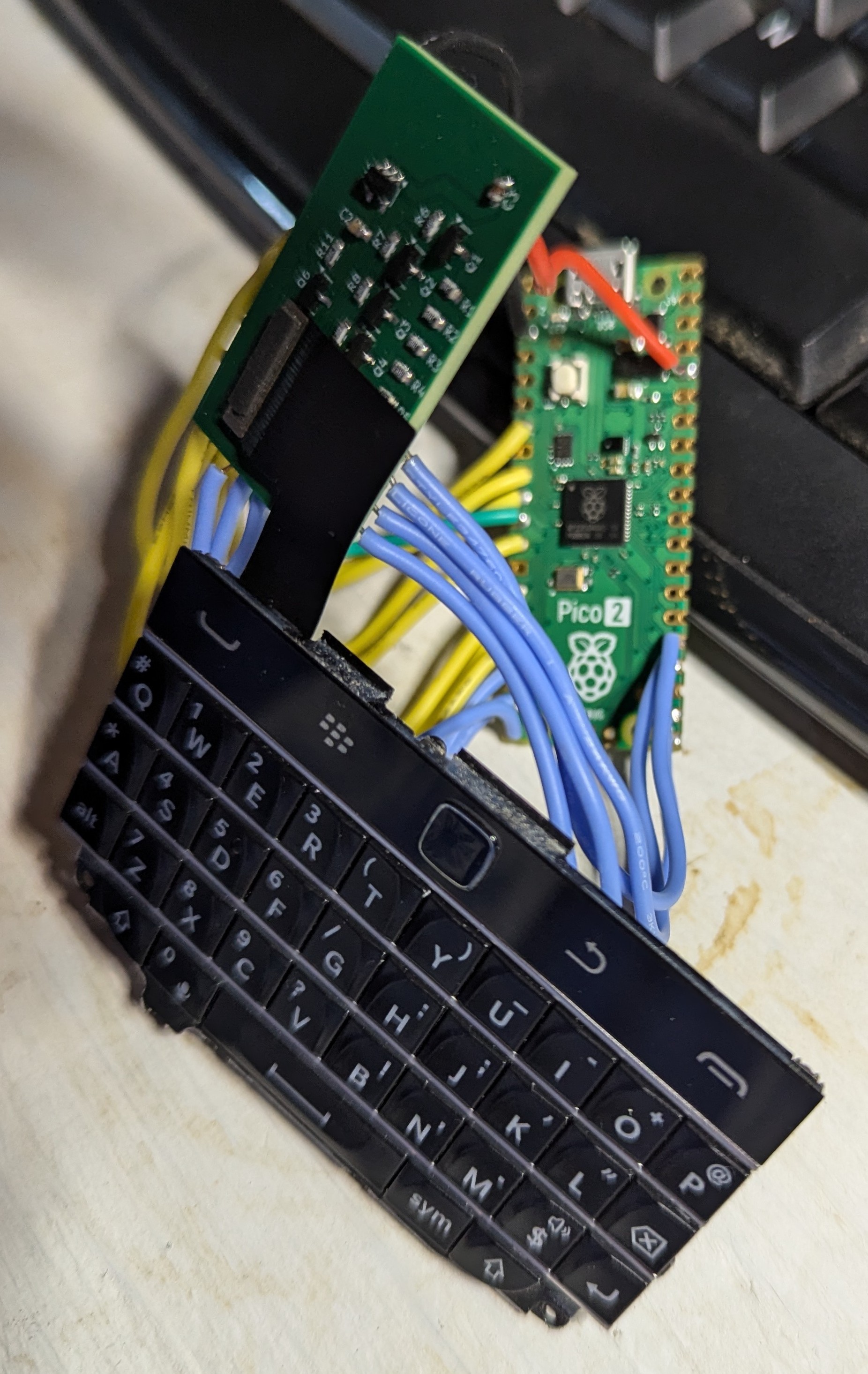
    I heated up the soldering iron, cut some lengths of wire, and soldered up this rats nest:

    It's ugly and mildly embarassing, but after I installed KMK firmware on it, I was able to make a seven pin column, seven pin row layout, then observe the firmware output as I pressed each key. Voila, a Blackberry Q20 Keyboard that can type until I break it! I still need to figure out the trackpad controls in KMK, mostly if it's possible at my technical skill level. Still, I did it. I made a keyboard, hurray!

    I still have another couple parts to test, but then it'll be time to draw up a motherboard that will combine all these disparate pieces of tech into an actual device. Unfortunately, life gets in the way: my wife and I very much want to move, so here sooner than later I'll have to tear down my bench to do wall work, then possibly again to move after said wall work. While it would be cool to have a functional device by the end of the year, I'm in no rush. Besides, a new house means a better workshop most likely!

  • Design 8: Easy Hack Oven

    janusprotocol09/14/2024 at 12:54 0 comments

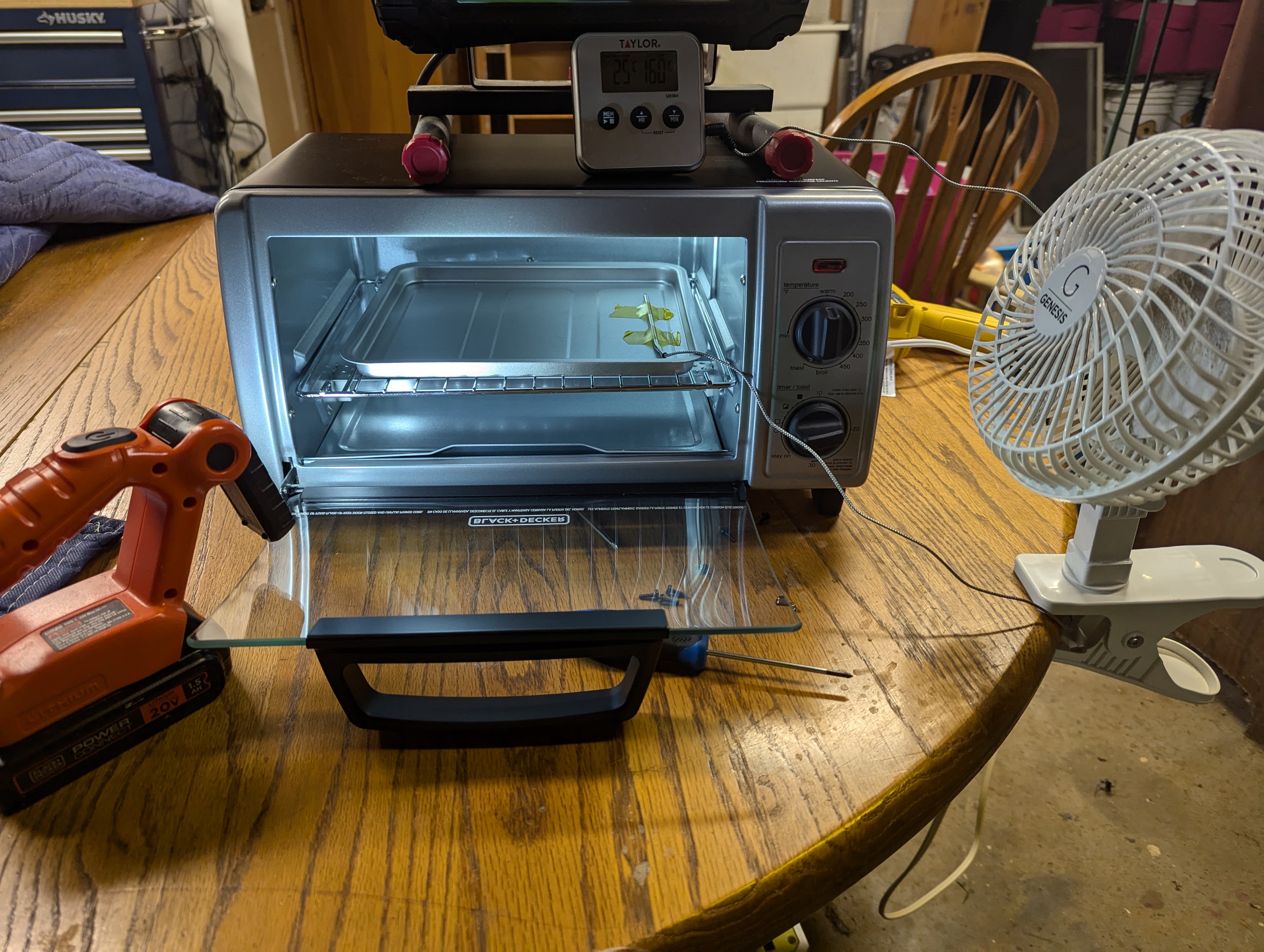
    While I waited for PCBWay to produce my boards and the accompanying stencil, I contemplated how I was gonna put this board together. I ordered a smaller, more controllable hot air gun, but as I got it from AliExpress it's unknown when things will arrive. I had read stories online about people hacking a toaster oven (AKA making an Easy Hack Oven) to act as a reflow oven, which was intriguing. After researching desired characteristics and what was available locally, I found a Black & Decker quartz element oven with power rating > 1000 W and reasonable price at Kroger, and I purchased a Walmart oven thermometer with probe. While my first thoughts were to go full send on hacking this thing, but as I thought more and more it seemed like I could just...watch the oven and control it manually for these IB backpack boards. So, I taped the probe to the oven tray, did some empty tests to get ramp rates and temp overshoot characteristics, and tested my planned procedure with solder paste only on the board.


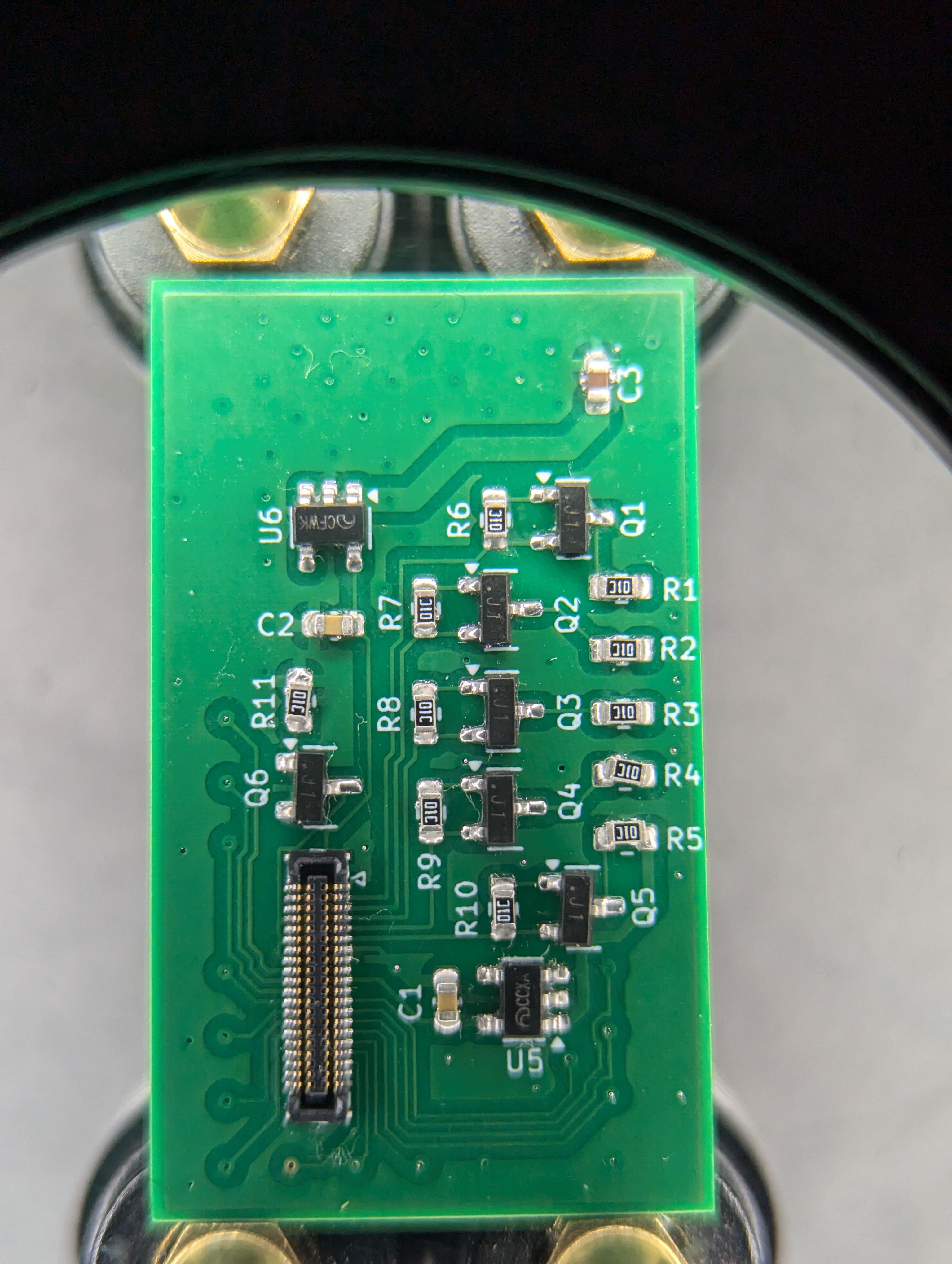
    That went well, so I applied paste with the stencil, placed components, and ran the reflow procedure. I did place kaptom tape on some of the in-pad vias, as I wasn't paying hundreds of dollars for PCBWay to fill them with resin. The hope for this was the tape would keep any molten solder from the pad from running out from under the board, which is why people fill vias in the first place when they're in pads. Anyway, during reflow I cut the oven power at 110 C, which cruised slowly over a minute or two to 155 C or so, then pulled the tray out an applied cool air via a handheld fan until the temperature dropped to 120 C. At that point I removed the board from the tray and placed it on my helping hands platform to rapidly cool. 

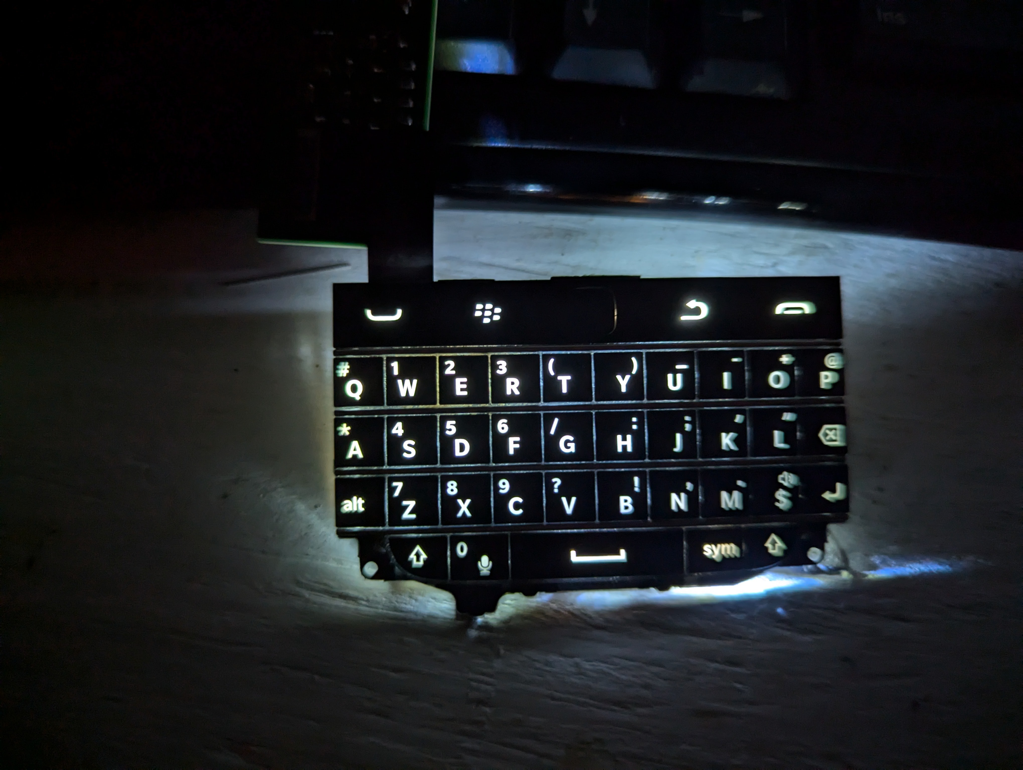
    The only flaws noticed were the C3 capacitor falling off almost immediately, R5 was comically skewed off of one of its pads, and the Hirose connector had a single solder bridge across pins 4 and 5. I resoldered C3 and R5, then resolved the bridge with some flux and a poke from my soldering iron. While I don't have any firmware ready to drive the keyboard, I can easily program the board via Arduino IDE to control the brightness of the backlight via PWM output from the IB 32U4 Pin 5. It looks SO much better than my initial test, which is super encouraging.


    I guess now I need to buckle down and figure out if I can use QMK or some other existing keyboard firmware package to drive the keyboard or write my own. I'm closer to the end of this phase of the project than the beginning, and once complete I have to test some display in a similar manner. I'll probably start designing the motherboard for the HB1 at that point as well, since my experience with the IB 324U really demonstrated the power of these prefabbed boards to expedite prototyping.

  • Design 7: Limited Success

    janusprotocol09/08/2024 at 12:13 0 comments

    After winging about delays last week, I made some leaps and bounds!

    As mentioned last week, I impulse purchased an ItsyBitsy 324U 3.3V 8MHz board from Adafruit (here) because part of my problem prototyping anything that needs a bunch of auxillary devices, like oscillators and diodes, suddenly becomes a nightmare to quickly slap together. Thus, with all of that nonsense taken care of, I was able to rapidly type out a short proof of concept Arduino sketch that would behave something akin to a keyboard. I was able to print the letters Q and G to screen on my workbench Linux by connecting a COL output to a ROW input, much in the same way as what would happen with a keyboard, and it worked! I'll at least be able to get something moving on this module.


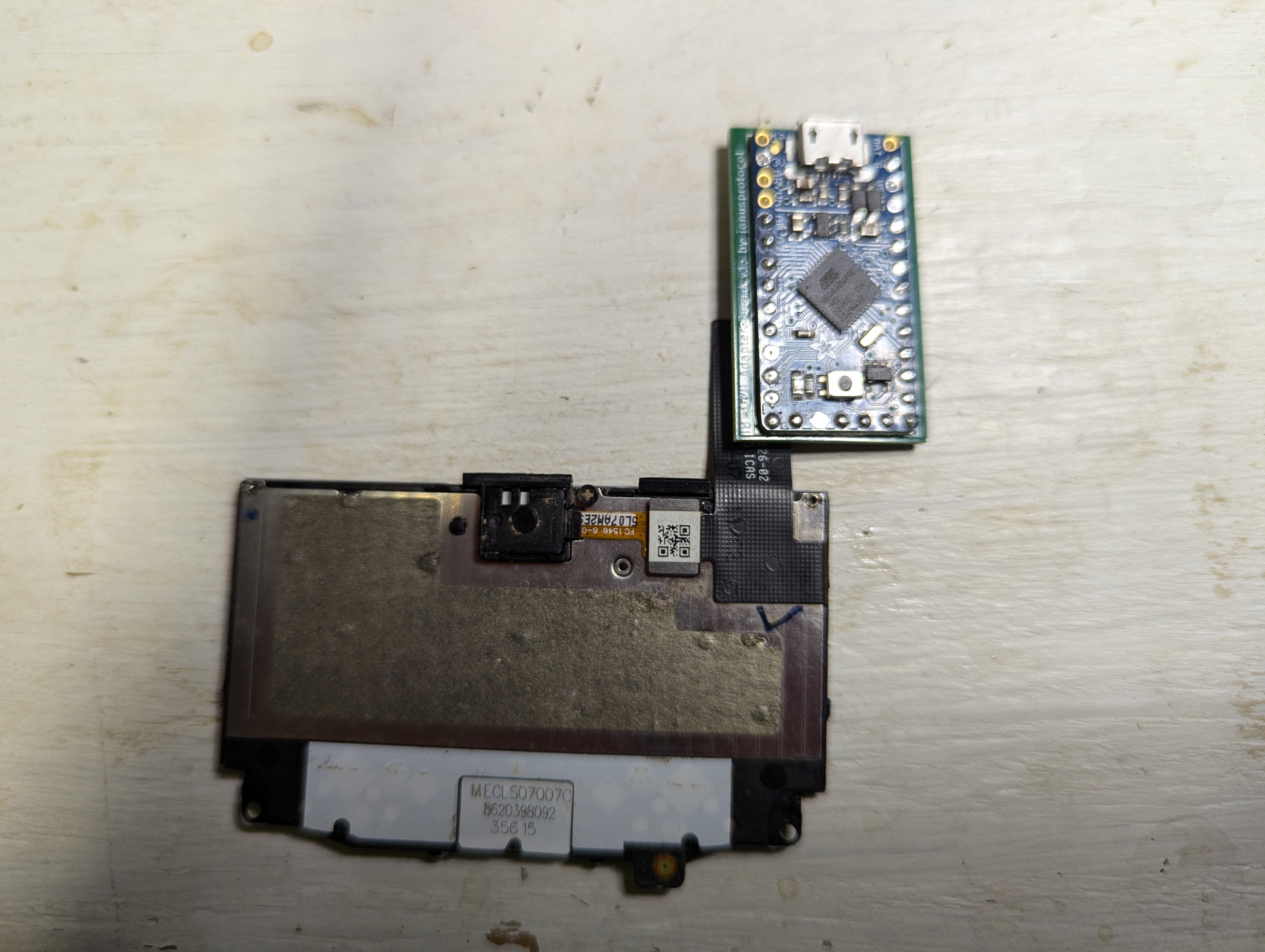
    But how am I gonna get a keyboard attached to this thing, let alone the BBQ20 with its special squirrel adapter? I decided to bite the bullet and design a new adapter board using some of the circuitry from this handheld keboard module as source material. Since I figured it'd take me much longer to figure out the keyboard firmware than this hardware, I decided the smart thing would be to make this adapter board into a board for the ItsyBitsy (hereafter IB) in order to use the existing hardware to make life easy.

    I've uploaded the KiCad files for this adapter board, feel free to use them as you see fit.

  • Design 6: Distractions Abound

    janusprotocol09/01/2024 at 01:29 0 comments

    As the title implies, I have had an incredibly distracting end to the summer. My actual job has been getting pretty intense recently, plus both my wife and I caught COVID for the first time (she's still reeling from it) and school started for our kids. Thus, while I have had some things going on I've neglected logging anything. 

    First, I found out that first keyboard probably isn't bad. After testing all the ones I ordered (like six or seven) they all have those same keys causing problems. Second, I realized the little gold plated pins in these Hirose connectors are ultra fragile, and I think the heat from my soldering iron melted the plastic housing a bit, which in turn pulled some pins out of alignment or bent them or whatever. Thus, I need to rethink my soldering station, and I'll have to likely replace my PEX plumbing heat gun for a real hot air rework station. Another issue is that my v1 board layout is terrible in practice: the pins get in the way of the connector! Also, I easily have the space to provide at least some dedicated voltage regulation on the board, which would make wiring the thing up to a microcontroller much easier.

    Speaking of the keyboard MCU, I decided to buy an Adafruit ItsyBitsy ATmega32U4 3.3 V 8 MHz board to streamline the process. The board was dirt cheap and has all the other stuff the ATmega needs around it, and what do I care if I solder all that shit onto a board myself for a prototype? I believe I can construct a small adapter board that would have the IB soldered to the back, while the front would contain the Hirose connector and some power regulator devices. The USB port of the MCU is what I was intending to use as a test connection, and here it is all in one little package! 

    Before I design and order a new board to do this, I need to get the chip installed with qmk firmware or some other equivalent (oh god please I don't want to homebrew a keyboard driver) with a simple test circuit to test the firmware. If I can get the Q20 to spit out a letter I think I'll be confident enough to go ahead with round two of board ordering.

    Action Items:
    0) buy a microUSB to USB-A cable that carries data (most difficult step)
    1) get Q20 firmware from somewhere and figure out how to install it
    2) wire up 2-3 COL pins and 2-3 ROW pins into the IB, plug into a computer, and type some letters

  • Design 5: Can I Even Work With These Things?

    janusprotocol08/04/2024 at 14:29 0 comments

    I finally received my custom boards from OSBPark, and I got some fresh solder paste in the mail so I was able to begin soldering Hirose connectors to pads. This was probably a poor choice of component for my first forays into SMD soldering, as the feet of the Hirose connector are super fine pieces of metal. I used a jumper lead to gently brush paste onto the copper pads, placed the connector, and then heated it with my heat gun until it melted. Of course, I had some bridged connections, but I fixed them with my soldering iron set to 350 by poking at the bridges until they resolved. It seems to have worked alright, though I did lose pin 38 out of the connector. Luckily that pin is not connected to anything, so could be worse. 

    During this process, I realized that I have no idea how to tell if any of this is done right. As in, how am I supposed to know this keyboard works when I'm not entirely sure how to get it to talk to a microprocessor? How could I ever tell if the issue was related to the board or to the firmware I loaded onto the microprocessor? To confirm my keyboard connector worked, I needed to devise a non-MCU driven way to check that all the connections are sound and that the keyboard is producing the correct signal when a key is pressed.

    I investigated how keyboards are designed. Generally, they have a row and column configuration, and an MCU will "scan" the keyboard by placing HIGH across the column inputs. Each column would see this HIGH signal once per scan, and the MCU would "listen" at the row outputs for a signal. As a MCU controlling a keyboard has a clock cycle in the order of 10s of MHz, that means the keyboard MCU is scanning each column for row inputs every 100 nanoseconds or so. 

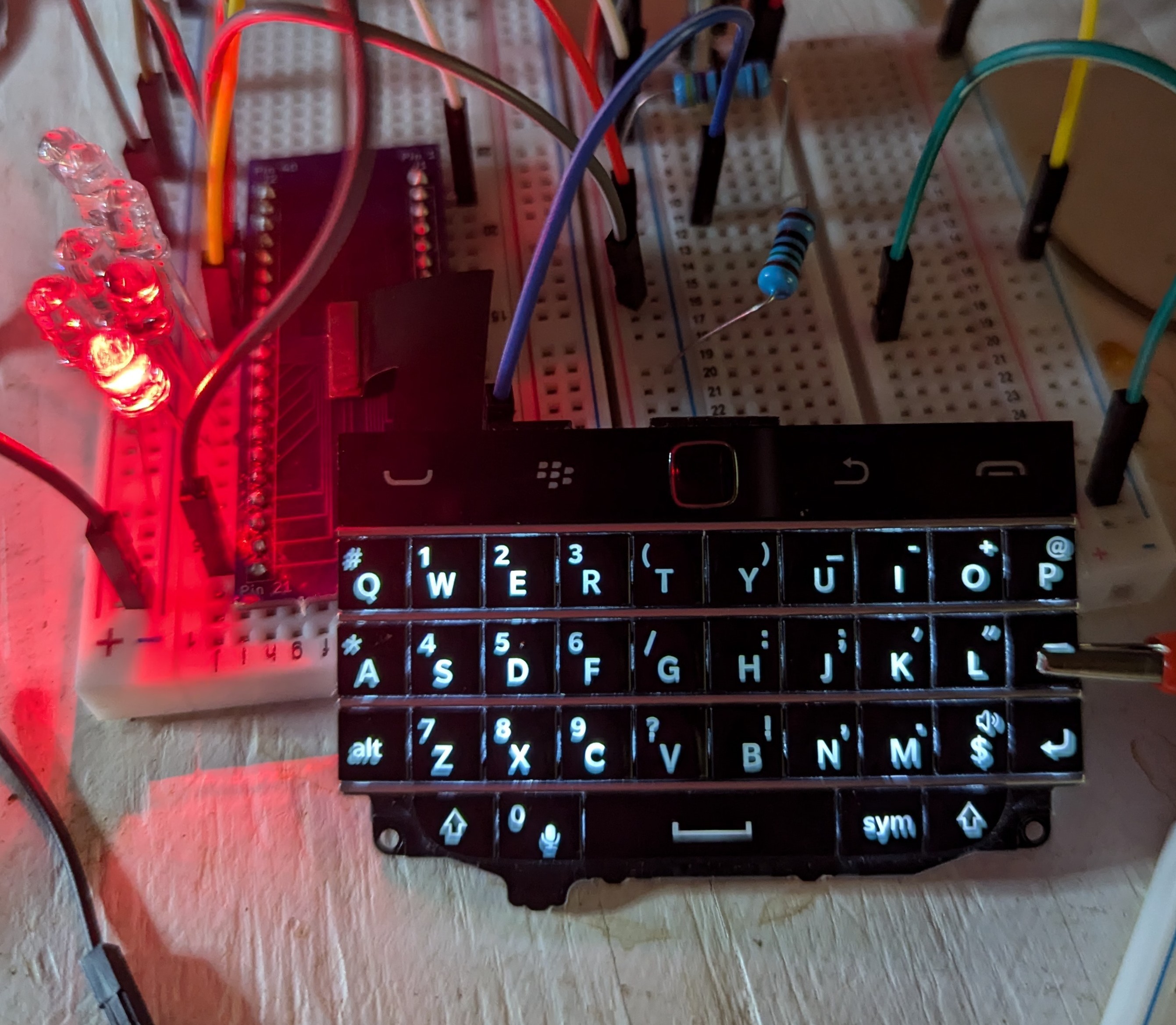
    Learning this, I devised this plan: put ~1.8 V on each COL pin on the keyboard (pins 12-18) and add an LED from each ROW pin (26-32) to ground. Thus, as all columns are now powered as if they were being scanned, when I press a key the corresponding LED will report which row is being connected to the power from a column. Using this initial setup, I could map key/row relationships easily, which I recorded into a spreadsheet. Then, I removed power from each column, one at a time, and checked which keys were disabled, which would mean that they were powered by the column I had disconnected.

    Only COL5 and the LED backlight is powered in this photo, and a clip is pressing the BKSP key to demonstrate the LED mapping of the keyboard.


    This worked very well, and I was able to quickly map this keyboard. I did note 7 keys that did not power an LED ever when pressed, and I also noted that no key appeared to need COL7 powered to output signal. While at first glance this may suggest that we simply have a broken COL7 input (either keyboard or connector), the keys aren't exactly in the most reasonable place for a final keyboard column. Additionally, I also got the keyboard backlight to work, but it seems like some of the LED backlights are not lighting up.

    The weird backlight and the key issues mean I very well could just have a broken Q20 keyboard. I did buy it on AliExpress, and there's some junk on the back of the board that suggests it could've been pulled from a BBQ20 unit, so only the gods know what happened to this component before it arrived. I thus decided to buy five of the things: if all of them malfunction in the same way, that means I've got a botched connection. If they behave properly, it means that first keyboard is simply broken, probably by a previous owner.

  • Design 4: Receiving

    janusprotocol07/30/2024 at 11:23 0 comments

    I've been receiving odds and ends via Amazon over the last couple of days. Working on microelectronics like this is a bit out of my wheelhouse, as most of my electronics collection dates back to the late 1990s before SMD was ubiquitous, so there's a ton of parts I need.

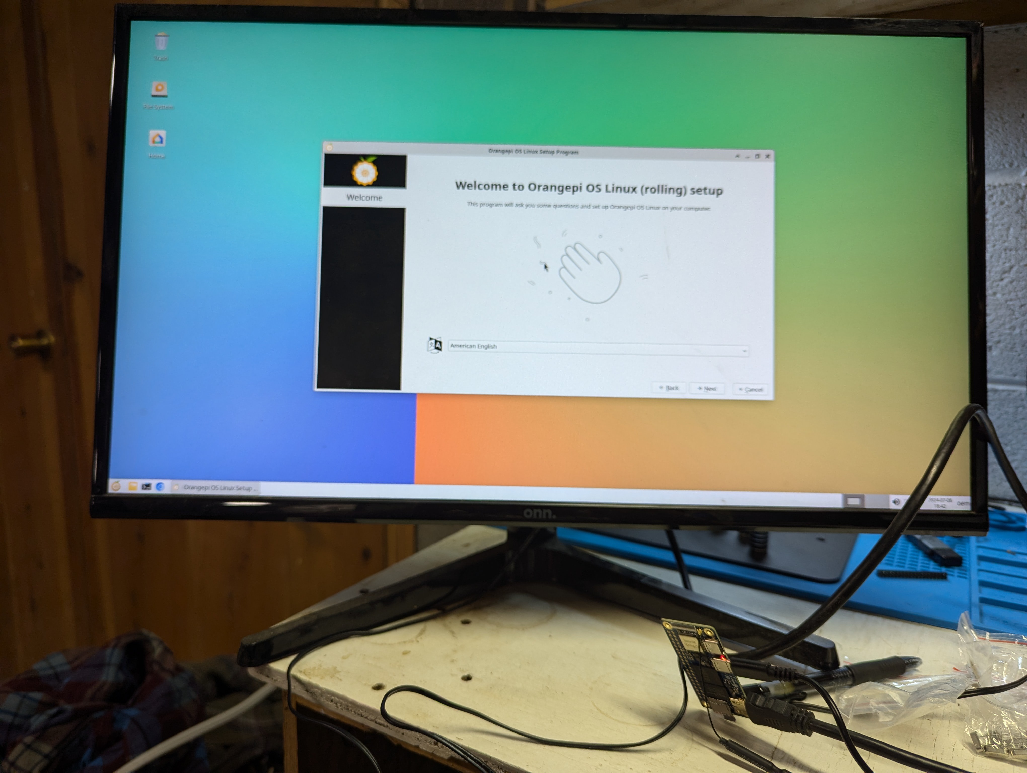
    In any event, I received my first order from AliExpress, which was significantly cheaper than Amazon for most of this stuff. I received the ATmega328PU chip, a 240x320 LCD screen, a couple SanDisk microSD cards of various sizes, timing crystals for use with the aforementioned ATmega chip and others in the future, and, last but not least, the Orange Pi 2 W 4G SoB. For the lattermost, as it's by far the most complex and expensive component, I decided to quickly flash Orange Pi OS to a 32 Gb card, then connect it to a monitor to see if it boots properly. It sure does!


    The last thing I need is the keyboard and the adapter PCB I ordered for it. The former should be here today, the latter should be here by the end of the week. Hopefully, I'll be able to make a log on Saturday showing the keyboard, LCD, and Opi connected together and functioning!

    Edit: I forgot to add that I'm considering switching to the ATmega32U4 to drive the keyboard. I'm still doing the research, and I'm definitely going to breadboard the device using what I have, but the final device may have a different chip in it. Power is going to be an issue, as with all handhelds, and I'm not sure the 328P is the best choice for that.

  • Design 3: PCB Adapter Design and Ordering

    janusprotocol07/21/2024 at 16:44 0 comments

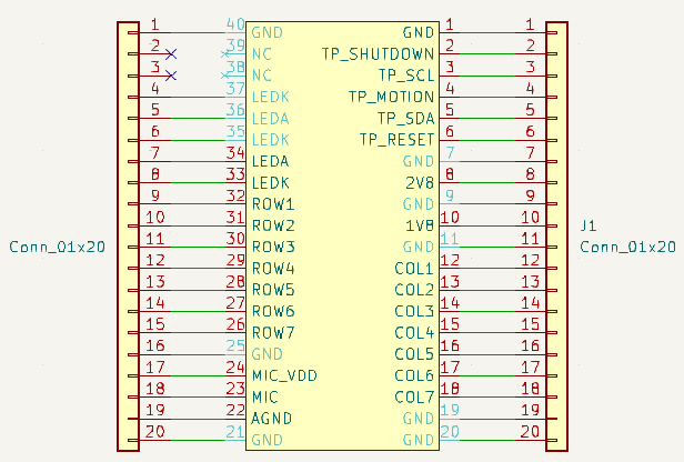
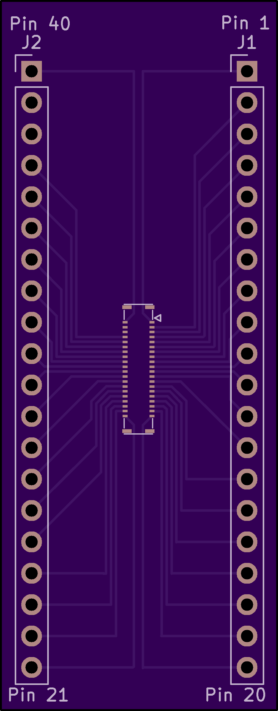
    Much to my dismay, I failed to find any PCBs on the internet that would serve to adapt the Q20 keyboard to pins suitable for prototyping. However, the Q20 is a component of the Solder Party Q20 handheld keyboard, which has all the hardware schematics in KiCAD format here. I was able to extract the symbol and footprint info from this schematic, save it, and build the following below. As this was my first experience with KiCAD, it took about six hours (lol) to figure out how precisely to get this to work. The secret was redoing the symbol with all pins, even the hidden ones, connected to a 1x20 pin connector on either side.

    Once all that was done, it was simply a matter of organizing the footprints and cutting the board into some sort of compatible shape. I separated the two columns of pins by 17.5 mm, which should provide 1 or 2 breadboard connections per pin (the pins should go into the third hole from the center of each row). I ordered the board through OSH Park (www.oshpark.com), 3 for 10. They look pretty good too! I added the KiCAD files for anyone who wants to order them.

  • Design 2: Ordering to Prototype Core Capabilities

    janusprotocol07/20/2024 at 15:50 0 comments

    I feel the first step is to get the core components working: that means the Orange Pi, the keyboard and its associated microprocessor, and the display breadboarded and functional. To this end, I ordered the necessary components to begin. One problem I already see is the keyboard connector: it's surface mount only, and I can't find a breakout board for that style of connector. I may need to design and order my first custom boards for this application. I'm going to spend a few days looking around the internet before I commit to that course of action.

  • Design 1: Capabilities

    janusprotocol07/20/2024 at 15:48 0 comments

    The intent for this device is to be a functional pocket terminal/phone made with off the shelf parts. I'd also like it to have some interesting features, such as built-in LoRa capabilities, an IR blaster, and GPIO ports for modules. Finally, I'd like a Linux OS over an Android, as I feel I'll use the increased features of Raspbian over Android. That may make for some annoying programming, but I can always dual-boot the device if I really need to.

    The core of the device will be an Orange Pi Zero 2 W 4 GB system, which is a lol-worthy Raspberry Pi knockoff. The hope is that 4 GB of RAM will let me use this as an actual pocket terminal, as I know I've had functional laptops with that amount of RAM. Depending on early prototyping results I may ditch this board for an official Raspberry Pi Nano.

    The Q20 keyboard device contains a trackball sensor and three soft buttons in addition to the Q10 keyboard keys. This choice was made obviously for the phone buttons and the trackpad. I plan to drive the keyboard with an ATmega328P-PU MCU running qmk firmware.

    The graphical display is a 240x320 resolution color LCD. Nothing fancy, but should interface with the Orange Pi fairly easily. This may change radically if the screen is too small (I'm bad with dimensions in my head).

    WiFi and Bluetooth will be handled by the Orange Pi board. I've selected a global 4G LTE cat4 modem, which has 150/50 Mbps up and down across all LTE bands (I think?). I also want to include a LoRa transceiver, mostly for show but also to tinker with low power HF applications, as well as a row of GPIO female pins on the top of the device for modular expansions (sensors, radios, etc.). Finally, I'd like to include an IR blaster, again mostly for its own sake but as a handy utility.

View all 10 project logs

Enjoy this project?

Share

Discussions

Similar Projects

Does this project spark your interest?

Become a member to follow this project and never miss any updates