-
Time to make a new version
09/27/2024 at 16:40 • 0 commentsUpdates
Since my last update a lot of things have happened.
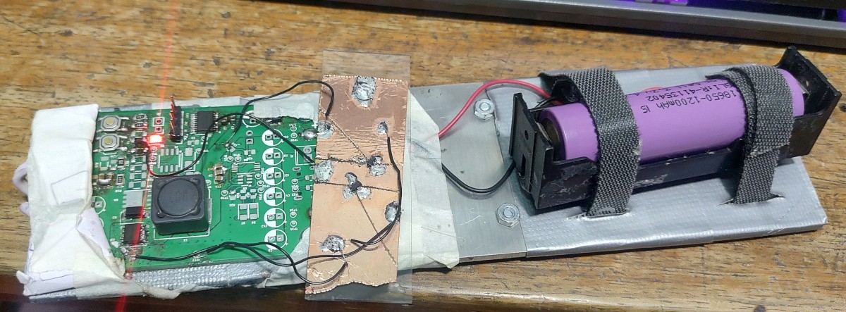
I took the torch with me on an evening walk the day I finished assembling the board and mounting it on the aluminium sheet. It was wonderful, being able to produce a lot of light, enough to make the dark spots light up is a great feeling. A power fantasy if you will.
I was able to illuminate a lot of cool things which would have not been visible otherwise.
![A mushroom colony A mushroom colony]()
illuminated using my phone flash ![Same mushroom colony Same mushroom colony]()
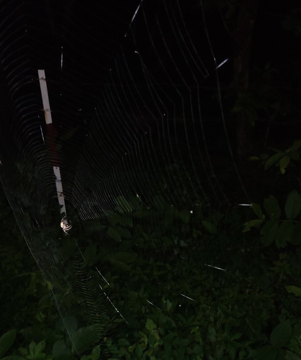
illuminated using my torch ![A spiderweb A spiderweb]()
illuminated using my phone flash ![Same spiderweb Same spiderweb]()
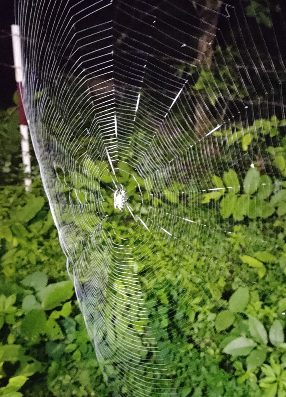
illuminated using my torch ![]()
I also soon received the 10uH inductors in mail, which I promptly put on the boards.
This reduced the output voltage at 1MHz a lot, so I had to reduce the switching frequency to 600KHz which did...nothing?
Turns out there were 2 limitations.
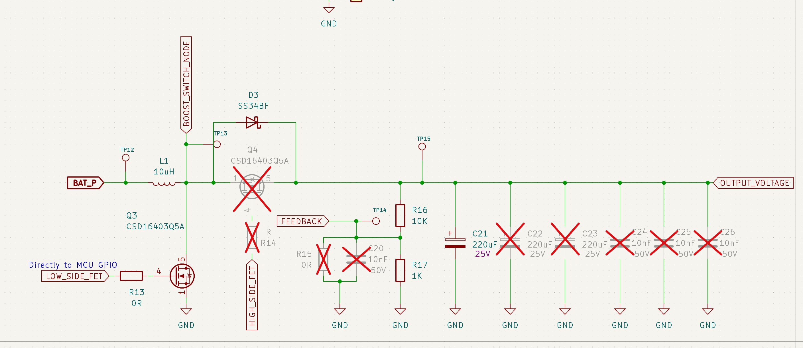
- The FET gate is directly connected to the MCU GPIO, which makes the turn on and off times extremely slow, essentially adding a hard limit to the max switching freq that I could get without making changes to the circuit
- Somehow, even though it makes no sense, the low, low gate current was still resulting in crazy ringing.
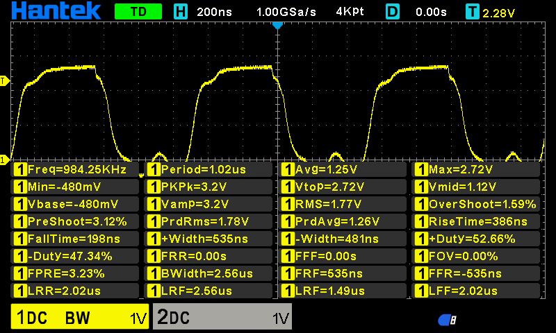
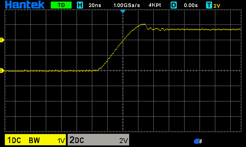
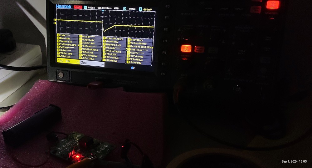
![Rise time Rise time]()
No gate resistor, straight from MCU 400ns rise time! Not very bad but the FET I am using has a total gate charge of 13nC, so they should be able to turn on quite fast.
I made a small board with a totem pole driver to make the switching faster. It made a massive difference in the switching times. There was still overshoot and ringing but at least rise-fall times were better, there was a lot less heating.
![]()
![Rise time Rise time]()
Rise time with the totem pole driver. Ringing was even worse now, but rise-fall times were much better and the FET was heating up less. Then I tried connecting a 7V SLA battery instead of the 3.7V li-ion cell, just to see how much brighter the LED would get. I just forgot that I had not implemented feedback in the code and it was running at a constant PWM.
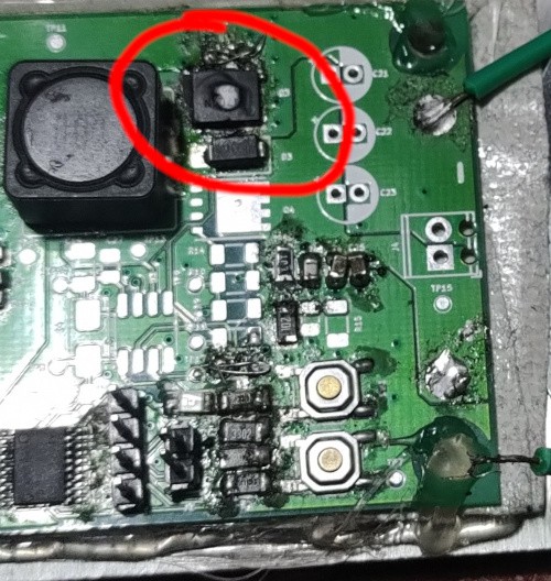
So that made the FET enter runaway and die, and the LED burn out as well. No worries I had plenty of spares. The MCU and everything else was still fine though.
![]()
Anyway I changed the FET and the LED, and it was all working fine again. I also swapped out the cell holder for a better one with metal tabs instead of spring, that made the resistance of the cell holder really drop down. No more losses.
I then implemented a simple control loop in the code, and changed the switching frequency to 200KHz. It was working perfectly fine, and it worked well with the ADC sampling at 400KHz.
As for the thermals, they were pretty decent. At ~10W output power, the main FET was too hot to touch, but the large copper plane made it still be able to run the board without rest.
There was a bigger problem though. At just 20W, the 3mm thick aluminium plate was getting up to 60C, and the LED itself was getting a lot hotter. With just voltage control, it was sure to enter thermal runaway.
I came close to having the LED burn out a few times, the temperature of the light turned a lot cooler suddenly and I knew it was time to turn it off.
![]()
That's all value I could get from this board. Its decent but without any current feedback, its just not suitable to drive the LEDs and be a torch.
Just for fun, I tested out the transient response of the code, and it was pretty decent I think at <1ms. I plan on using these boards as UPS for my raspi server and WiFi AP.
![]()
Now the problems
- The form factor was an obvious issue, as its pretty obvious, a long flat aluminium sheet does not serve as a good body for a torch.
- Another issue was that the 18650 holder was a cheap one with spring contacts, which were contributing a large amount of resistance in the circuit, and generating a surprising amount of heat/losses. The circuitry was not the power output limit, but the source impedance of the cell+holder. That's cool I guess.
- The 20W LEDs I bought were likely "factory rejects". Their price was 29₹ (0.32 USD) per unit, for starters. Another clue was that they all had different forward voltages and a few had a couple of LED strings dead. A bummer but that's what I get for trusting the price I guess. Still most of them worked fine.
![The LED The LED]()
- As expected, the MCU GPIO pins were too weak to drive the FET gate fast enough, but even with the minuscule amount of current, there was still ringing on the gate. Solved this with the add on board, but it should have been fixed by default.
- Voltage feedback is a bad way to drive LEDs. Should do current feedback.
- The diode wastes power. A synchronous boost converter would be much better. It would however need.
- I made a few mistakes while choosing the GPIO pins on the MCU. The wakeup interrupt pin was not selected to be connected to the mode select button was the most major issue but everything else was meh.
-
First Board
07/29/2024 at 04:46 • 0 commentsI assembled the first board and it appears to work fine.
The main inductor is supposed to be a 10uH one, but its yet to arrive in mail so I have used a 1.5uH one for the time being. The intended PWM for the boost converter was 600KHz for the 10uH inductor, but for the 1.5uH one, I'm using 1MHz, straight from the MCU GPIO without a buffer or gate resistor :D
I have hence not made any power measurements either. The LED does seem to heat up at 70% duty cycle, so does the FET, but anything lower than that, and I do not see any heating. The LED is dissipating maybe a few watts, but definitely not a lot.
Interestingly, I was seeing a lot of ringing on the FET gate but it disappeared when the duty cycle was increased.
![]()
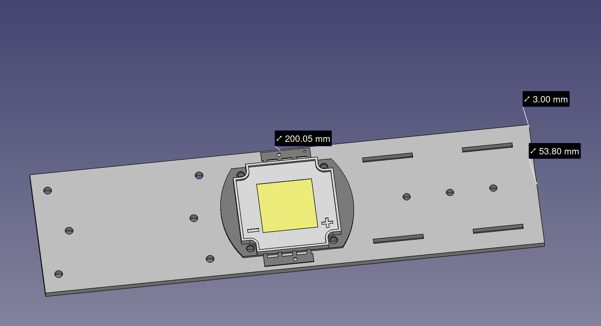
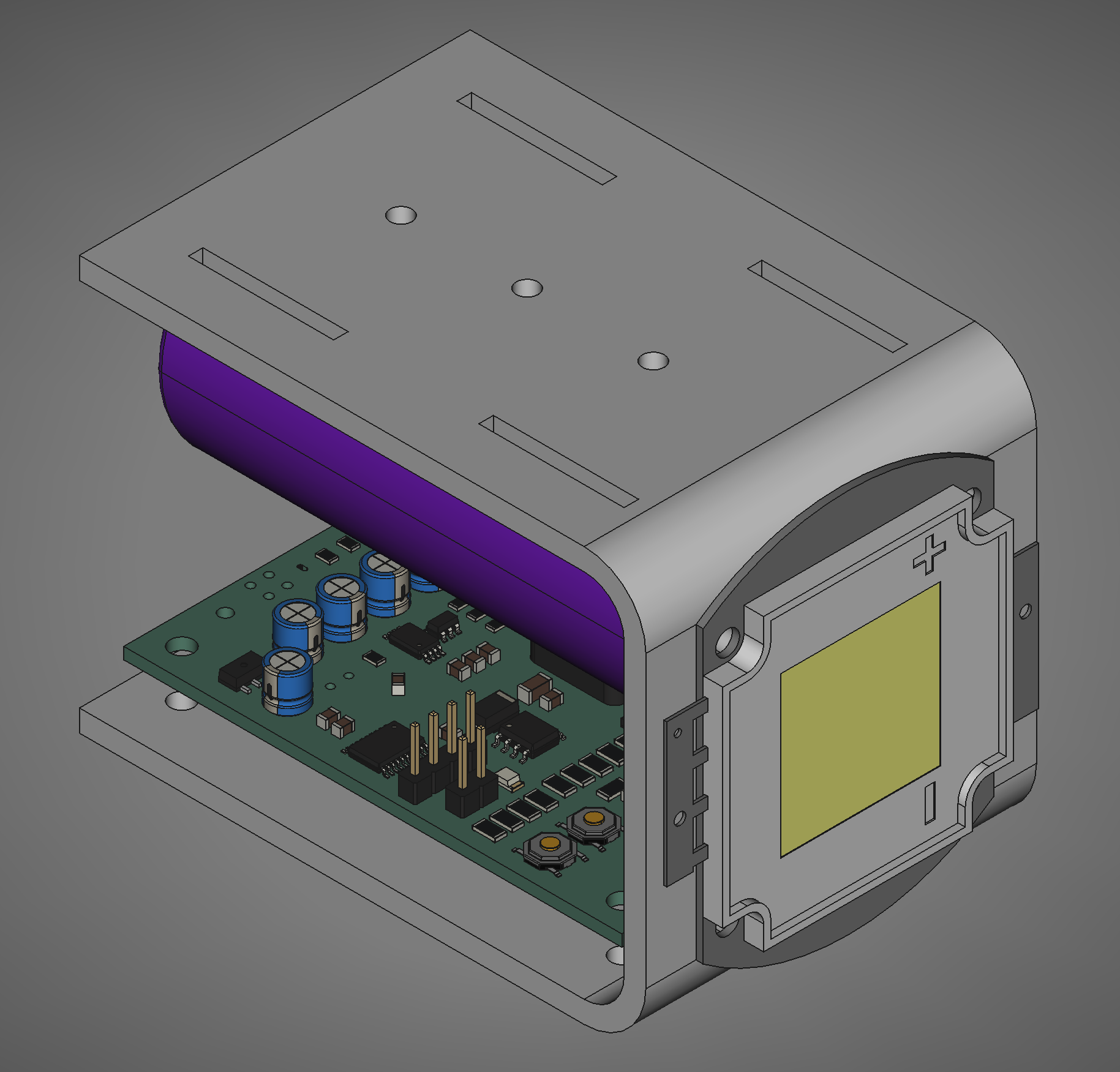
This was supposed to look like this but the company doing the sheet metal laser cutting refused to do the bending, and I discovered 3mm aluminum is a lot more stiffer than I expected and could not be bent by hand (yes I actually thought 3mm aluminum could be bent by hand)
![]()
Besides this, the circuit has no current feedback which is important for driving LEDs. I'll probably include it in the second version.
 Shrinath Nimare

