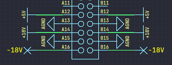
If 32 pin connectors are used, the pins will be more than sufficient. I assume to divide all pins into three groups.
- Power - power and ground lines of analog circuitry and control and switching system: -+15V +5V. In this case, use both sides of the connector, that is, two pins per signal.
- Control - control lines from components located on the motherboard. Each such line can include a relay. All control lines occupy a fixed number of pins on all connectors. However, while some of them come from one output per board (shared), others are dedicated exclusively to a particular board (specific).
- Special - the signal lines of a specific board. They are organized differently for different boards.
In addition to components for generating control signals, the motherboard has its own set of relays for switching specific signals of the tape recorder.
For example HF bias generator. It does not use -15V however its pin-out in the power supply section is the same as all other boards.
 The control section only uses specific signals, the other pins remain unused.
 h2w
h2w
Discussions
Become a Hackaday.io Member
Create an account to leave a comment. Already have an account? Log In.