 h2w
h2w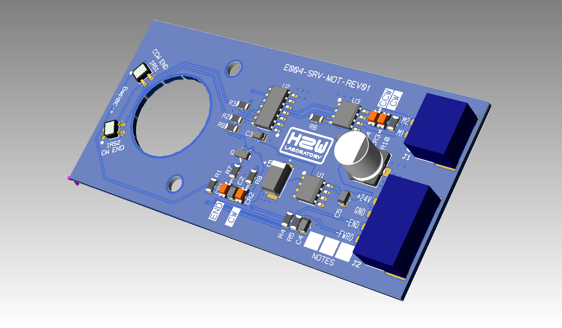
The final solution of the servo motor control board is based on the following solutions.
- Minimum number of pins on the connector from the control board. In which besides `GND` and +24V, there is a movement direction signal `CW` or `CCW`. And an end-of-motion signal `END`. The END signal should allow the control system to register error situations -- for self-diagnosis.
- The control board must control the 24V voltage to quietly turn on the system.
- The board must not contain a micro-controller.
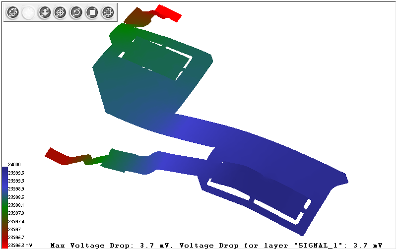
Despite the simplicity of the board, I performed a PI/SI simulation to evaluate the result.
Discussions
Become a Hackaday.io Member
Create an account to leave a comment. Already have an account? Log In.