0%
0%
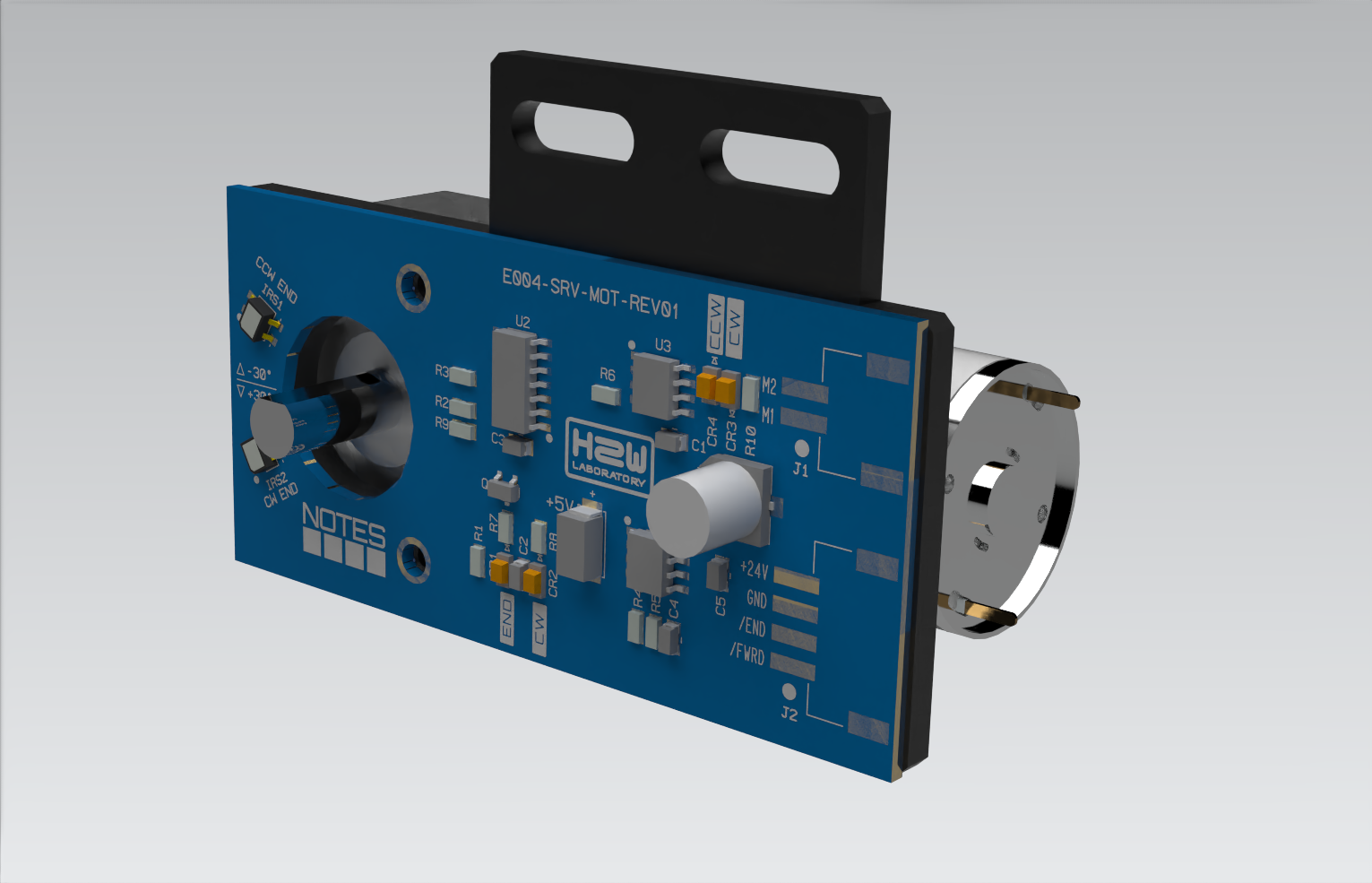
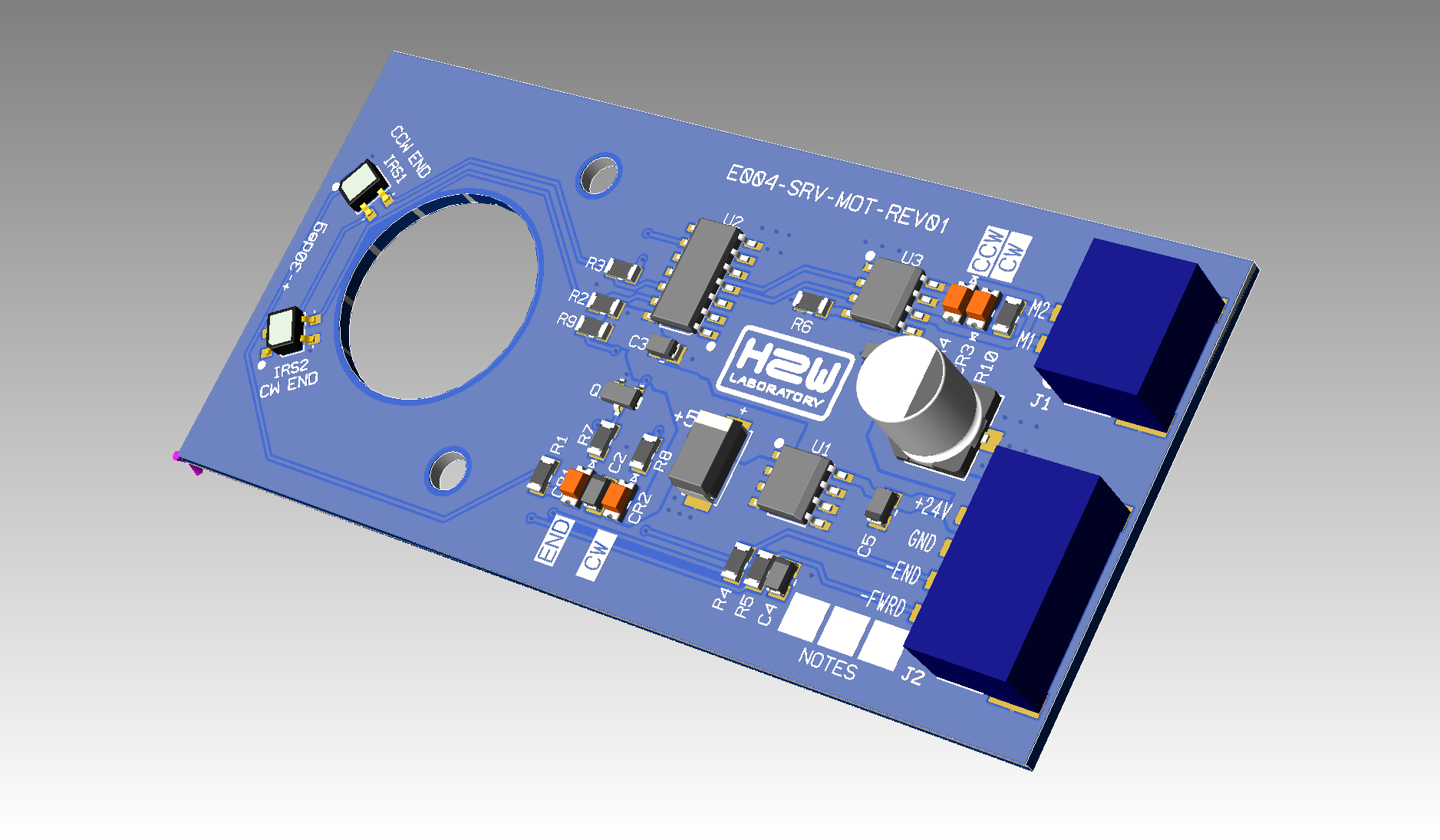
Renovation of the E004 audio tape recorder
A low-cost, high-quality tape recorder with a cross-board architecture.
 h2w
h2wBecome a Hackaday.io member
Already have an account? Log in.
Just one more thing
To make the experience fit your profile, pick a username and tell us what interests you.
Pick an awesome username
hackaday.io/
Your profile's URL: hackaday.io/username. Max 25 alphanumeric characters.
Pick a few interests
Projects that share your interests
People that share your interests
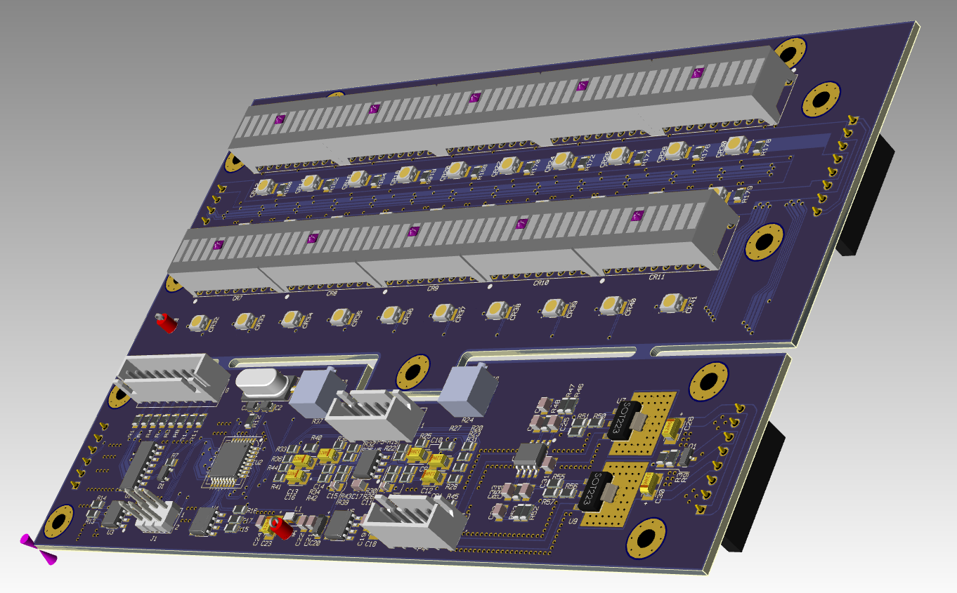
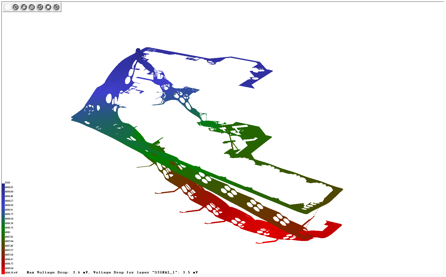
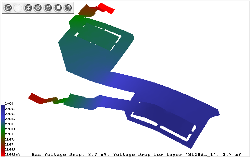
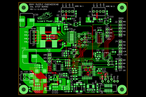
 It take time to minimize dropout on 2 layer's board.
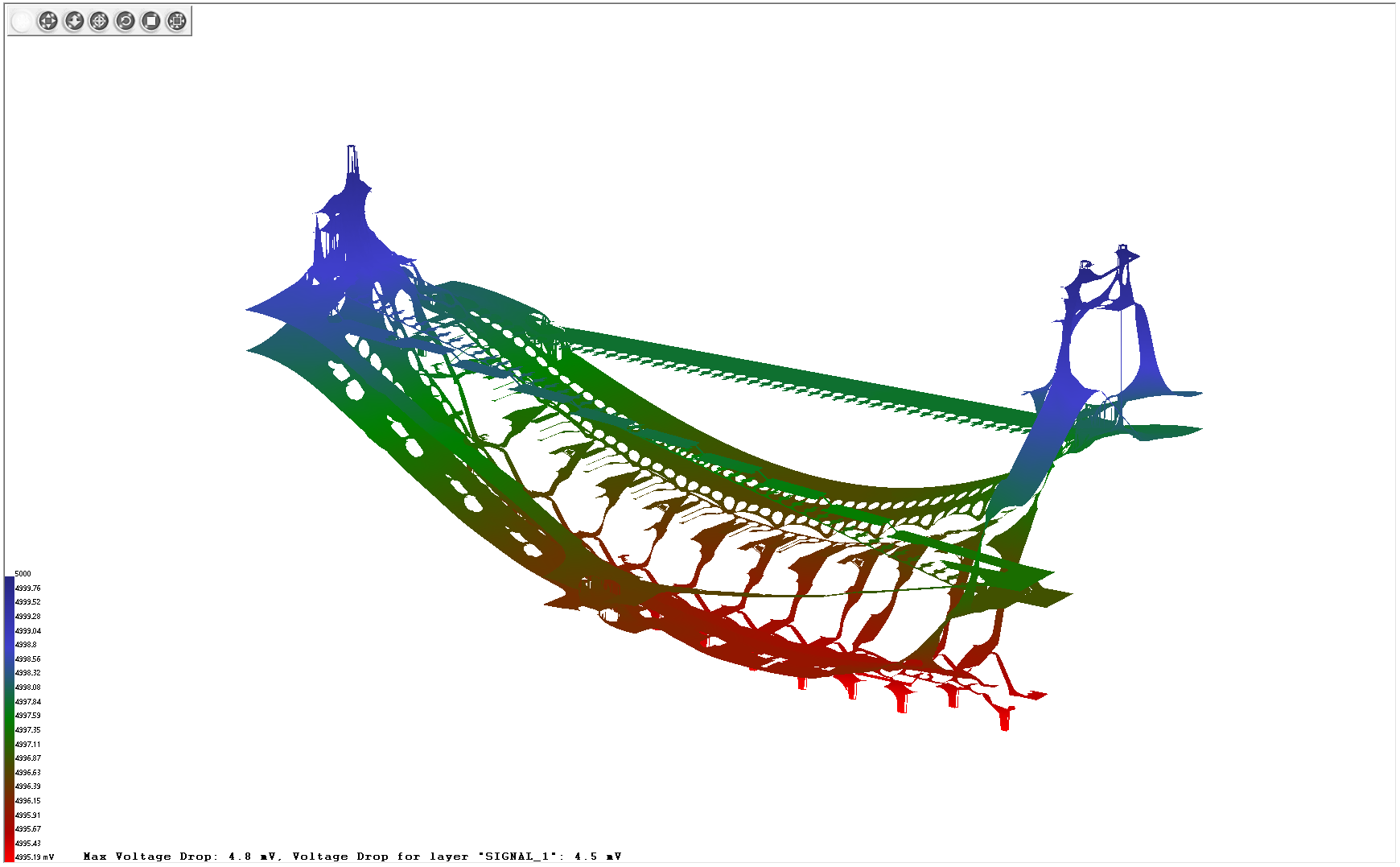
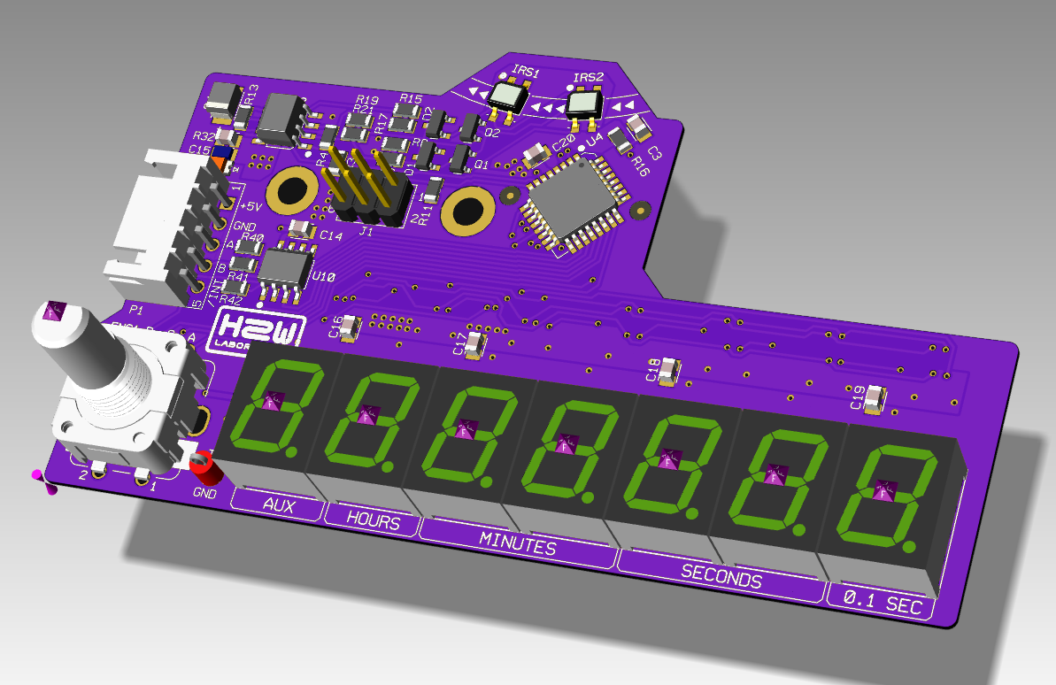
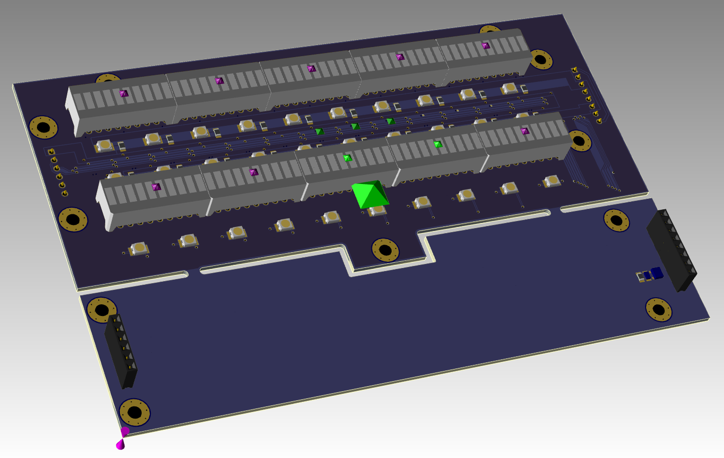
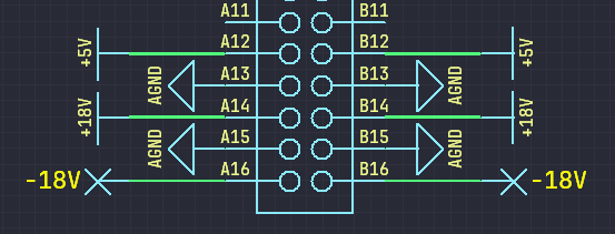 The control section only uses specific signals, the other pins remain unused.
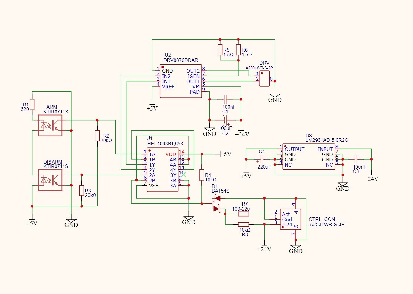

 Bharbour
 plugg.ee Labs
 Lex Kravitz
This is really cool!