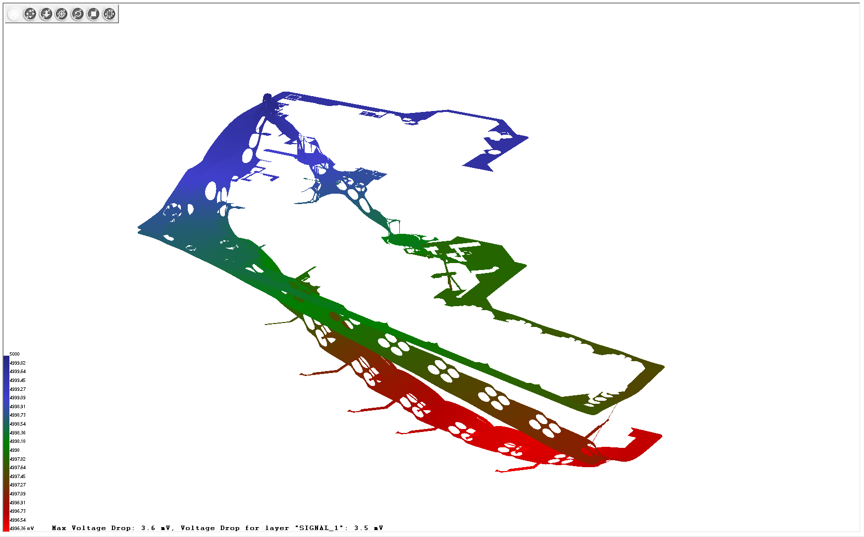
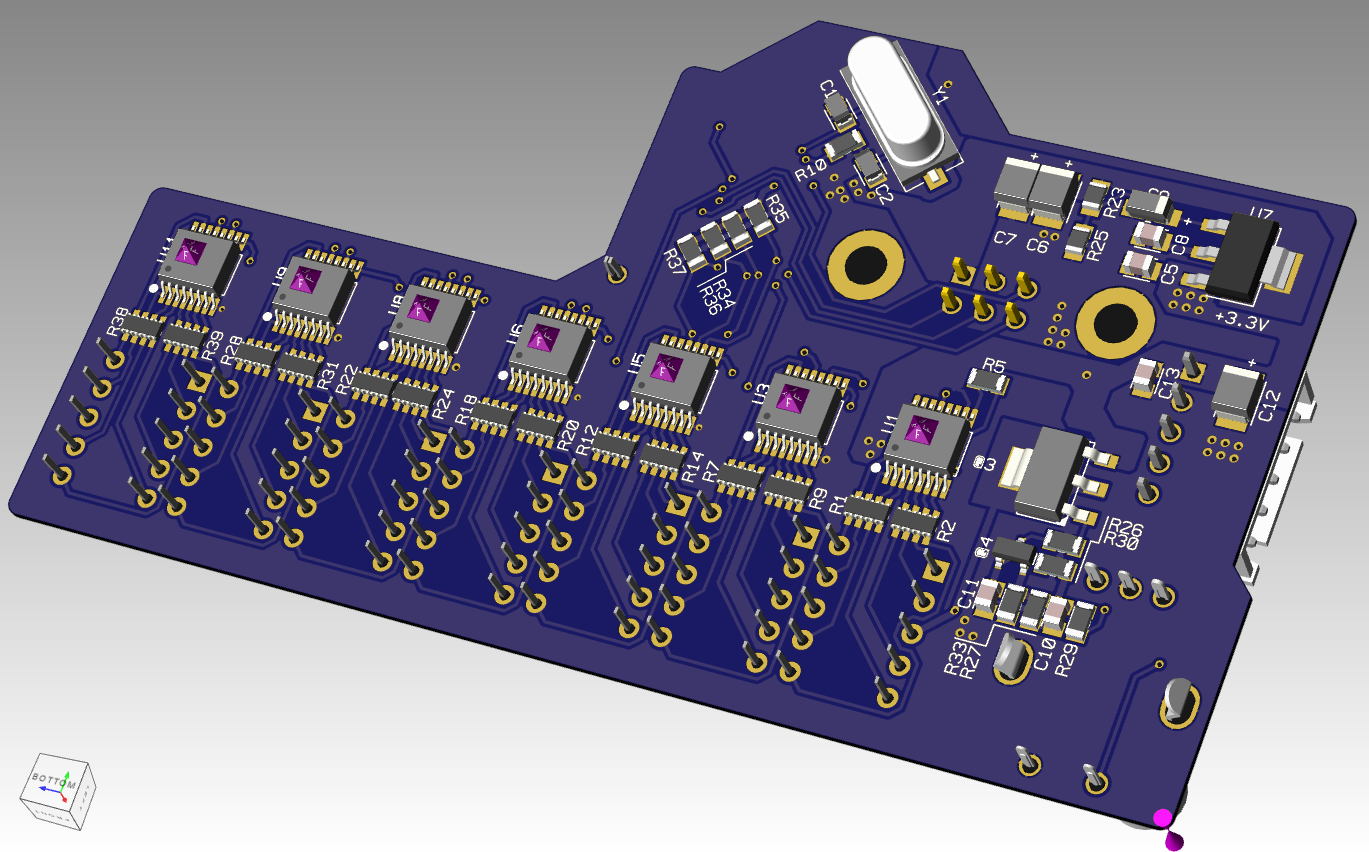
The VU meter attached to this project was madden with Altium. I decided to restart it with Xpedition because I wish to use PI-Verification. It take time to minimize dropout on 2 layer's board.
Voltage sensors use an optical pair and a moving shadow. The position of the shadow changes the amount of light passing through the phototransistor. As a result, the collector current is proportional to the absolute position of the tape tensioner.
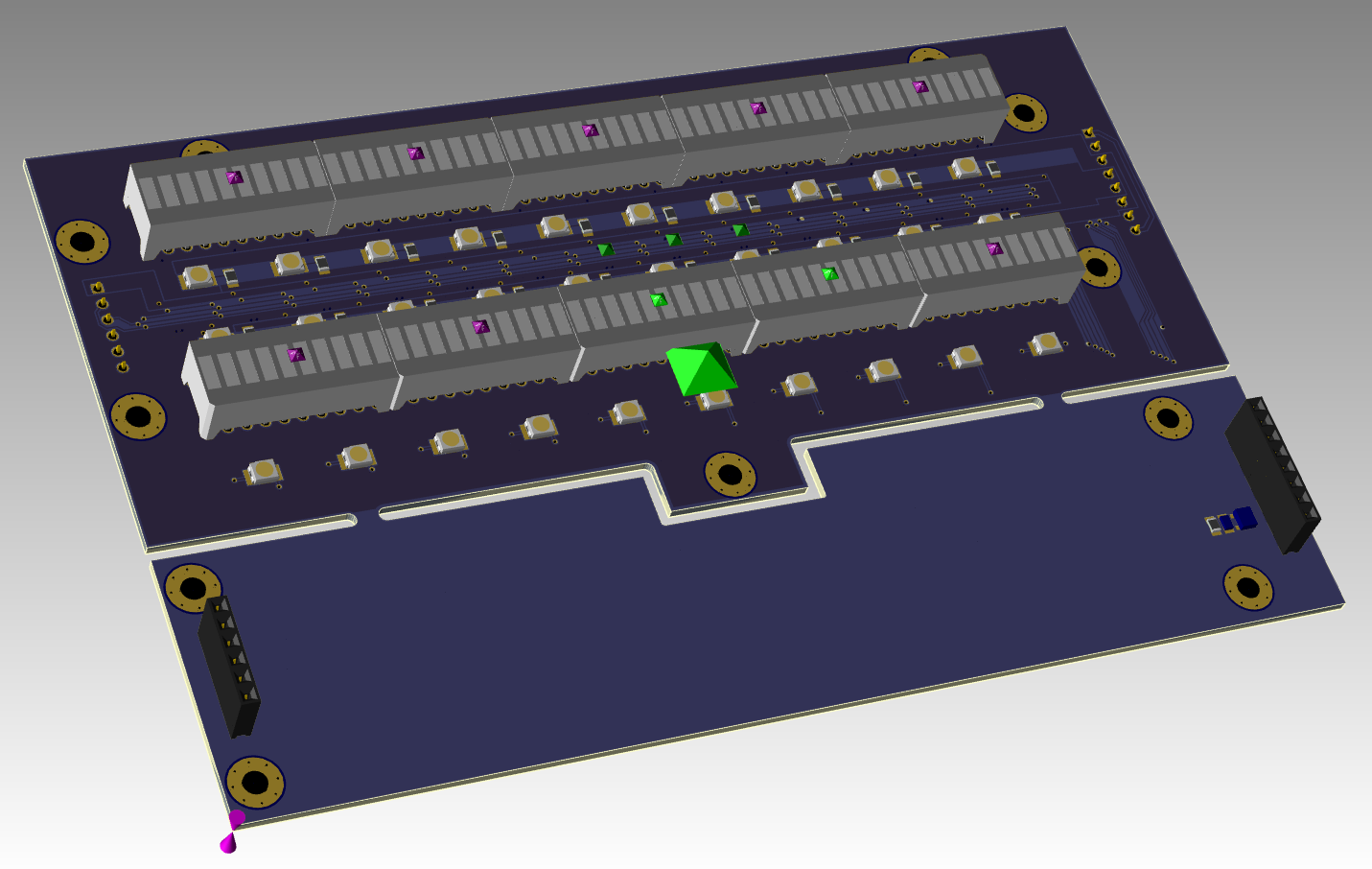
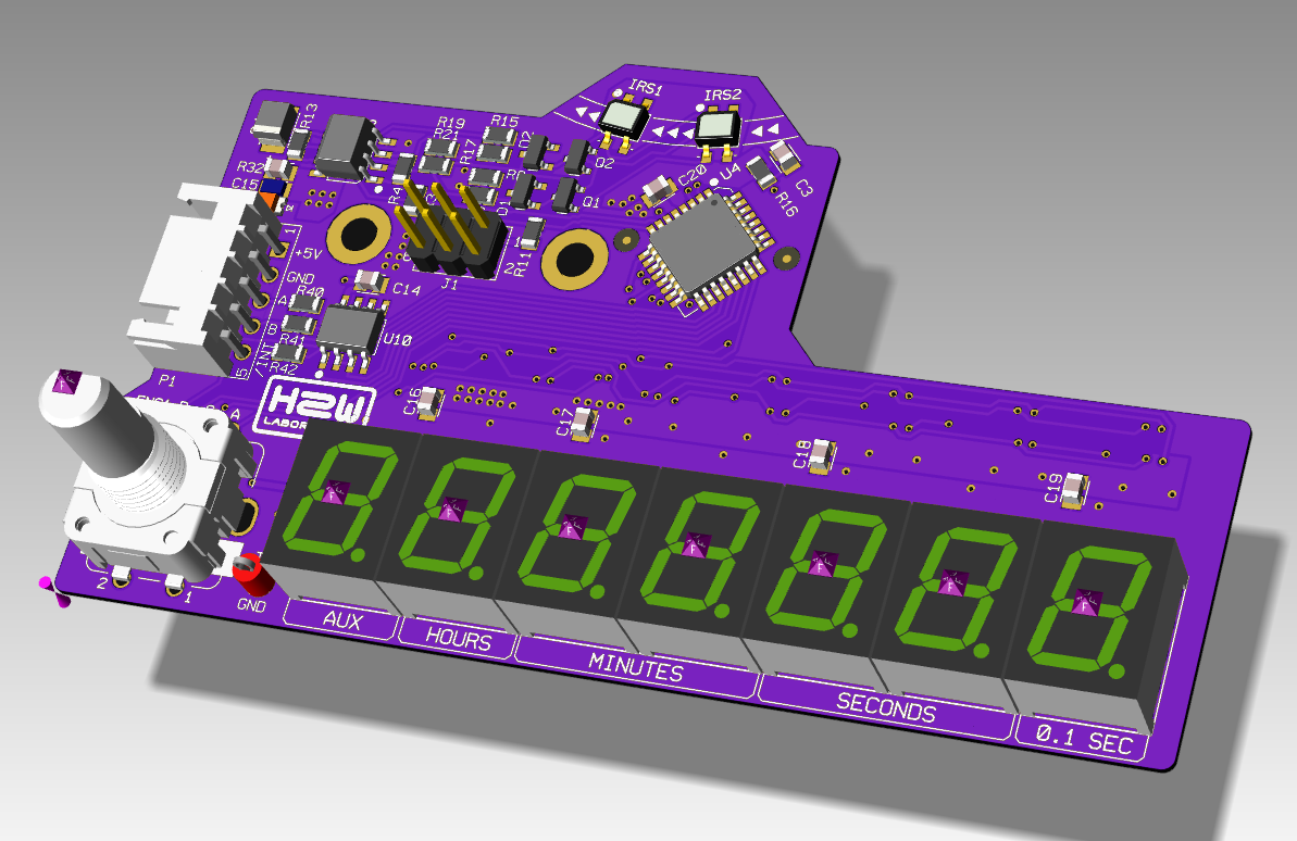
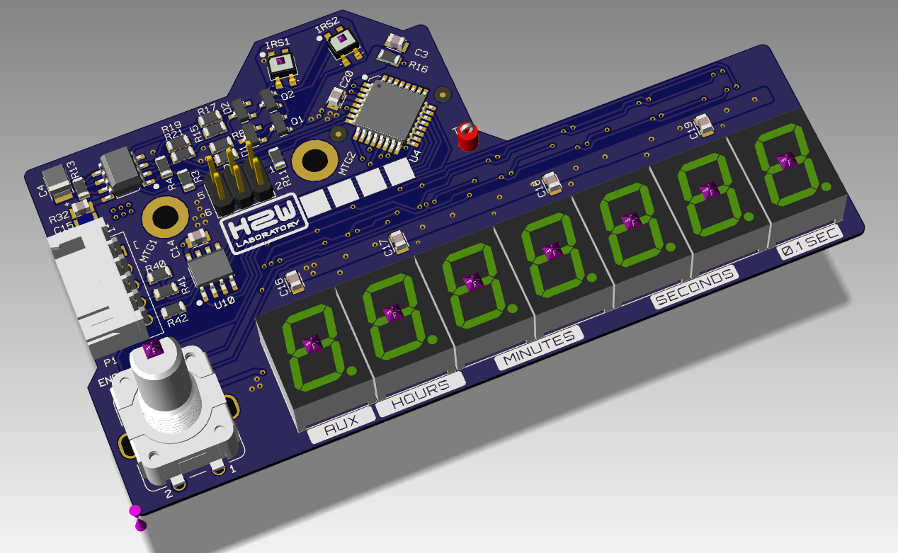
The final version of the counter is on the image below. With the size of the PCB and components (most of 0805) this is the best layout for the two layers board
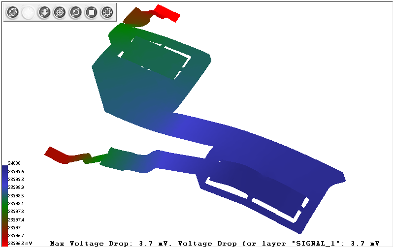
The power wiring is far from the perfect but acceptable for this case
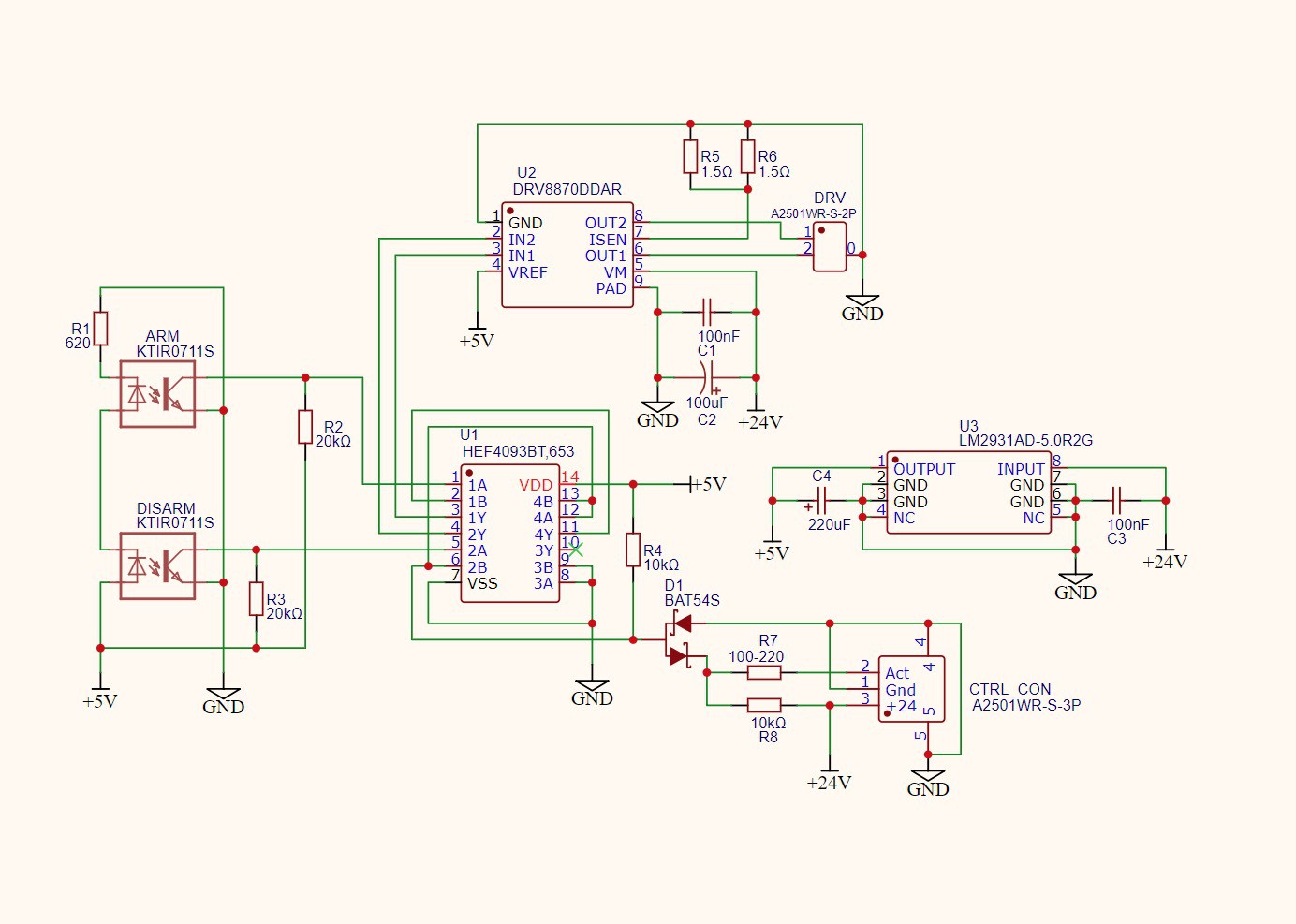
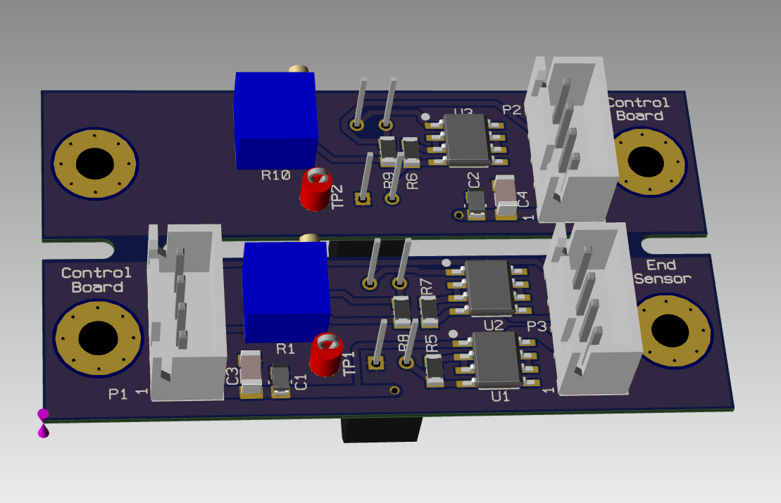
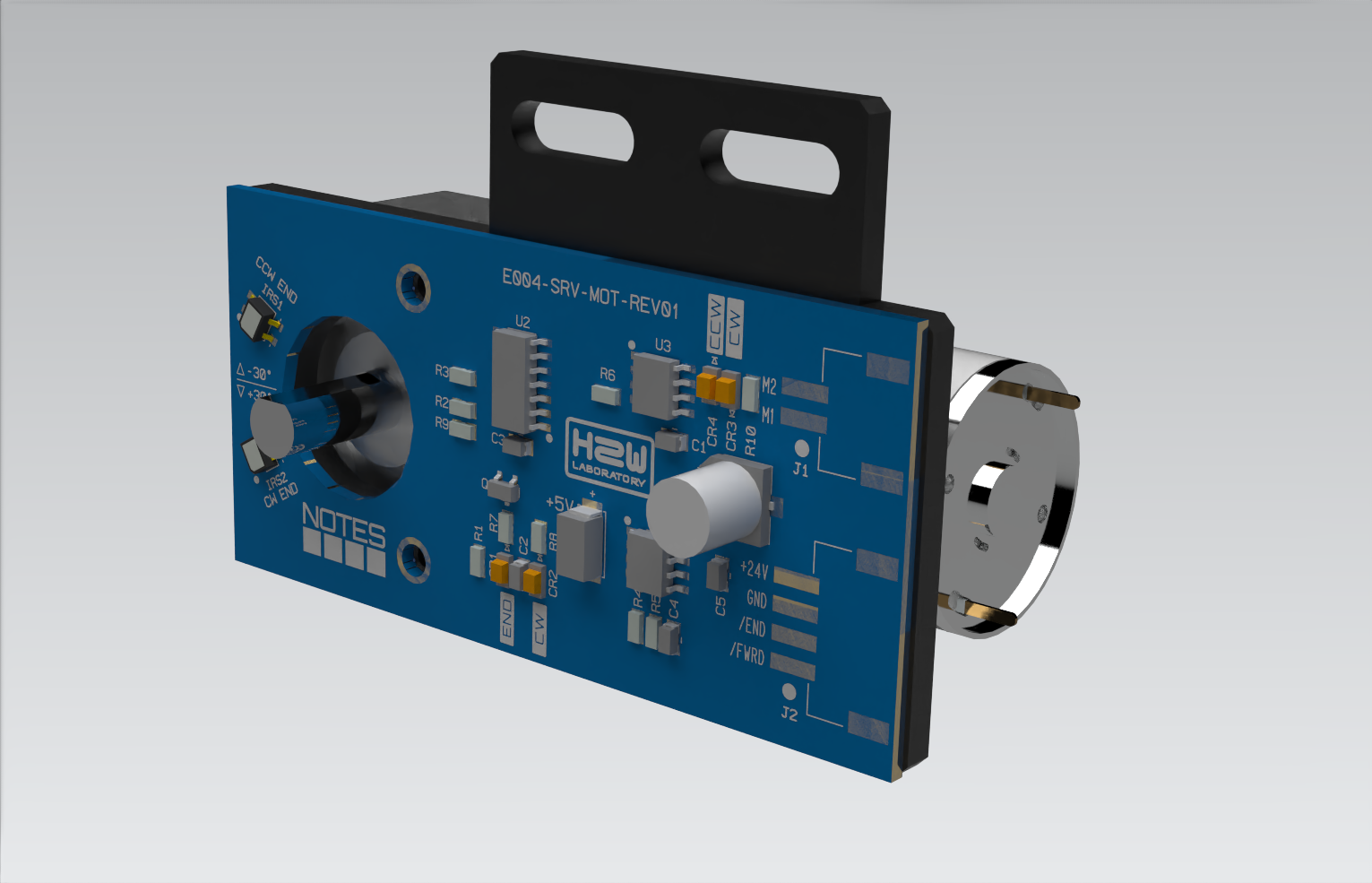
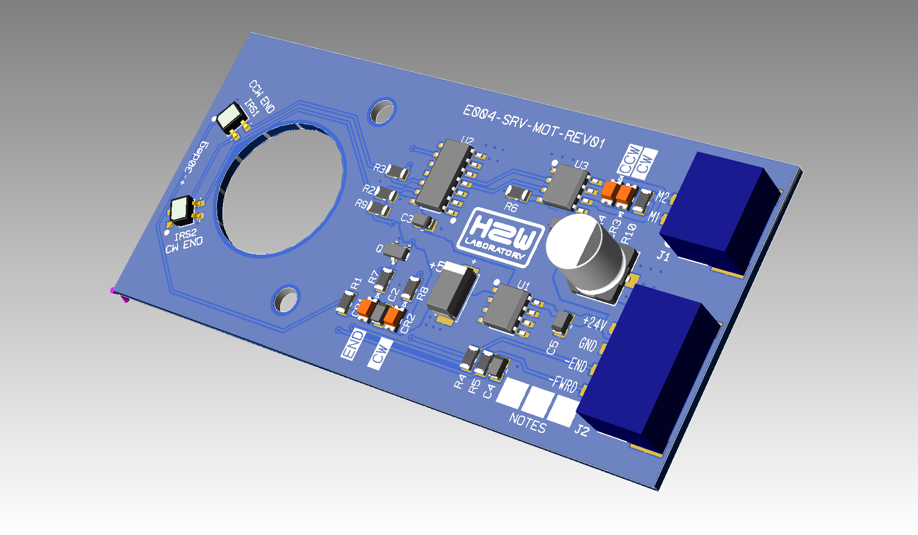
The final solution of the servo motor control board is based on the following solutions.
Minimum number of pins on the connector from the control board. In which besides `GND` and +24V, there is a movement direction signal `CW` or `CCW`. And an end-of-motion signal `END`. The END signal should allow the control system to register error situations -- for self-diagnosis.
The control board must control the 24V voltage to quietly turn on the system.
The board must not contain a micro-controller.
Despite the simplicity of the board, I performed a PI/SI simulation to evaluate the result.
If 32 pin connectors are used, the pins will be more than sufficient. I assume to divide all pins into three groups.
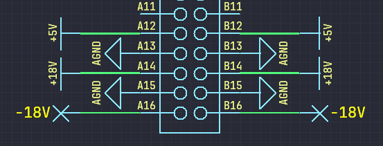
Power - power and ground lines of analog circuitry and control and switching system: -+15V +5V. In this case, use both sides of the connector, that is, two pins per signal.
Control - control lines from components located on the motherboard. Each such line can include a relay. All control lines occupy a fixed number of pins on all connectors. However, while some of them come from one output per board (shared), others are dedicated exclusively to a particular board (specific).
Special - the signal lines of a specific board. They are organized differently for different boards.
In addition to components for generating control signals, the motherboard has its own set of relays for switching specific signals of the tape recorder.
For example HF bias generator. It does not use -15V however its pin-out in the power supply section is the same as all other boards.
The control section only uses specific signals, the other pins remain unused.
A board from another developer uses a three-pin connector. This is a very simple and inexpensive solution. The pin-out of the connector is shown below.
GND - the ground for power and signal
+24V - the power for the servomotor
DIR - the direction signal: 0 - rotate CW, 1 - rotate CCW
The motor stops by itself when the marker reaches the optical sensor.
The disadvantages of this are:
The control controller has no status from the servo motor;
If the device is suddenly de-energized, the servo motor will start moving in the default direction when power is restored. This somewhat makes the process of powering up the device a bit daunting for the user
Solution 1 - With RS485
For more complete control you can use RS485 interface. Then there will be a pinout.
GND - power ground
+24V - power
A - RS485
B - RS485
However, this will require a microcontroller and interface converter to be installed on the board. This makes the construction more expensive.
Solution 2 - With I2C
It will be a little cheaper if you use I2C interface.
GND - power ground
+24V - power
GND - signal ground
SCL - I2C
SDA - I2C
Solution 2 - Passive
In this case only the motor driver is installed on the board. Then the pinout will be as follows.
GND - power ground
+24V - power
GND - signal ground
M1 - motor in1
M2 - motor in2
S1 - sensor 1
S2 - sensor 2
Conclusion
Tough choice considering the connectors and wires cost their money too. However, the RS485 option looks like the most noise-protected and therefore reliable option.
 h2w
h2w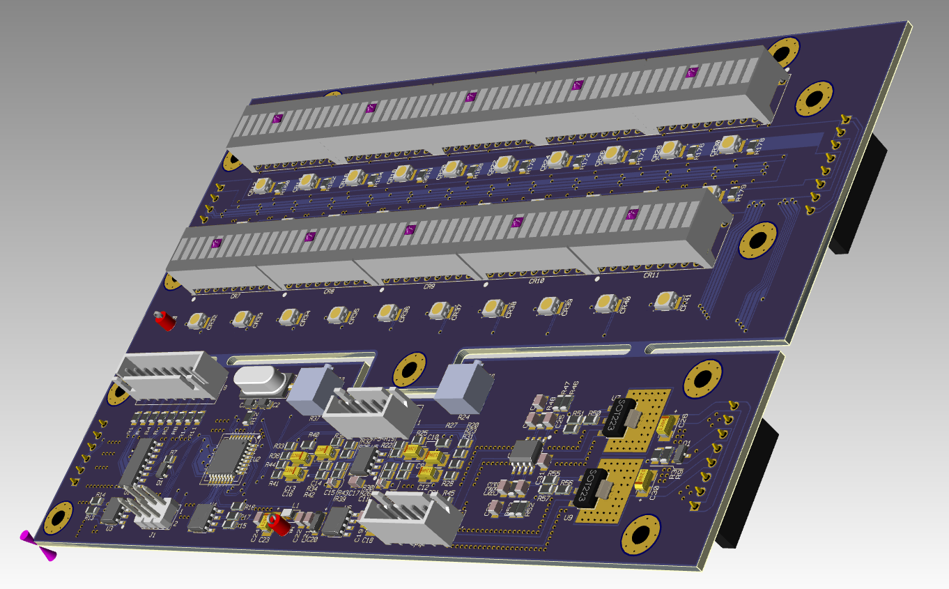
 It take time to minimize dropout on 2 layer's board.
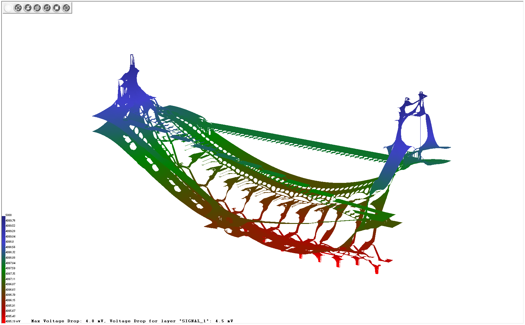
 The control section only uses specific signals, the other pins remain unused.