 h2w
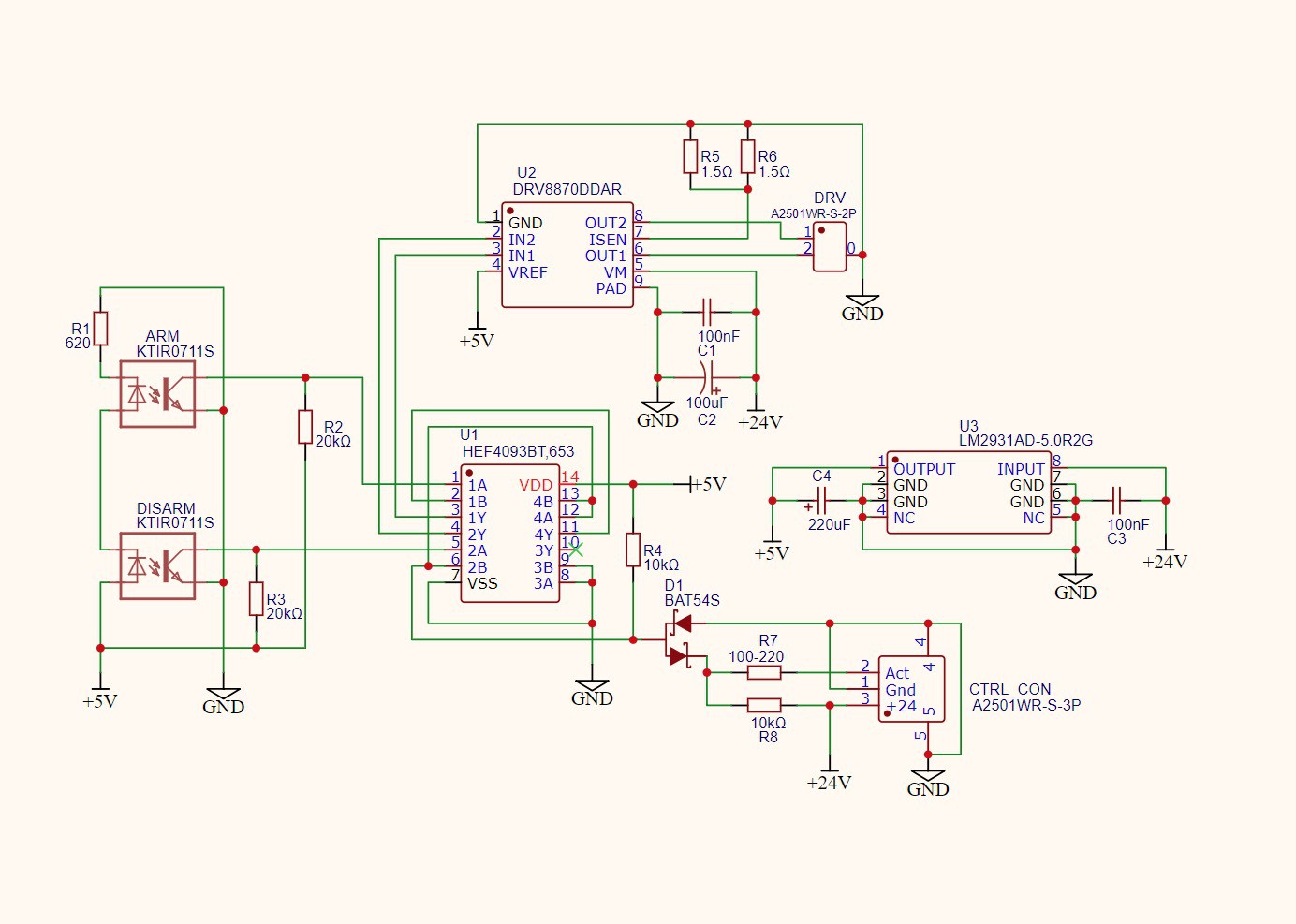
h2wA board from another developer uses a three-pin connector. This is a very simple and inexpensive solution. The pin-out of the connector is shown below.
- GND - the ground for power and signal
- +24V - the power for the servomotor
- DIR - the direction signal: 0 - rotate CW, 1 - rotate CCW
The motor stops by itself when the marker reaches the optical sensor.
The disadvantages of this are:
- The control controller has no status from the servo motor;
- If the device is suddenly de-energized, the servo motor will start moving in the default direction when power is restored. This somewhat makes the process of powering up the device a bit daunting for the user
Solution 1 - With RS485
For more complete control you can use RS485 interface. Then there will be a pinout.
- GND - power ground
- +24V - power
- A - RS485
- B - RS485
However, this will require a microcontroller and interface converter to be installed on the board. This makes the construction more expensive.
Solution 2 - With I2C
It will be a little cheaper if you use I2C interface.
- GND - power ground
- +24V - power
- GND - signal ground
- SCL - I2C
- SDA - I2C
Solution 2 - Passive
In this case only the motor driver is installed on the board. Then the pinout will be as follows.
- GND - power ground
- +24V - power
- GND - signal ground
- M1 - motor in1
- M2 - motor in2
- S1 - sensor 1
- S2 - sensor 2
Conclusion
Tough choice considering the connectors and wires cost their money too. However, the RS485 option looks like the most noise-protected and therefore reliable option.
Discussions
Become a Hackaday.io Member
Create an account to leave a comment. Already have an account? Log In.