-
1PCB Assembly
![]()
![]()
![]()
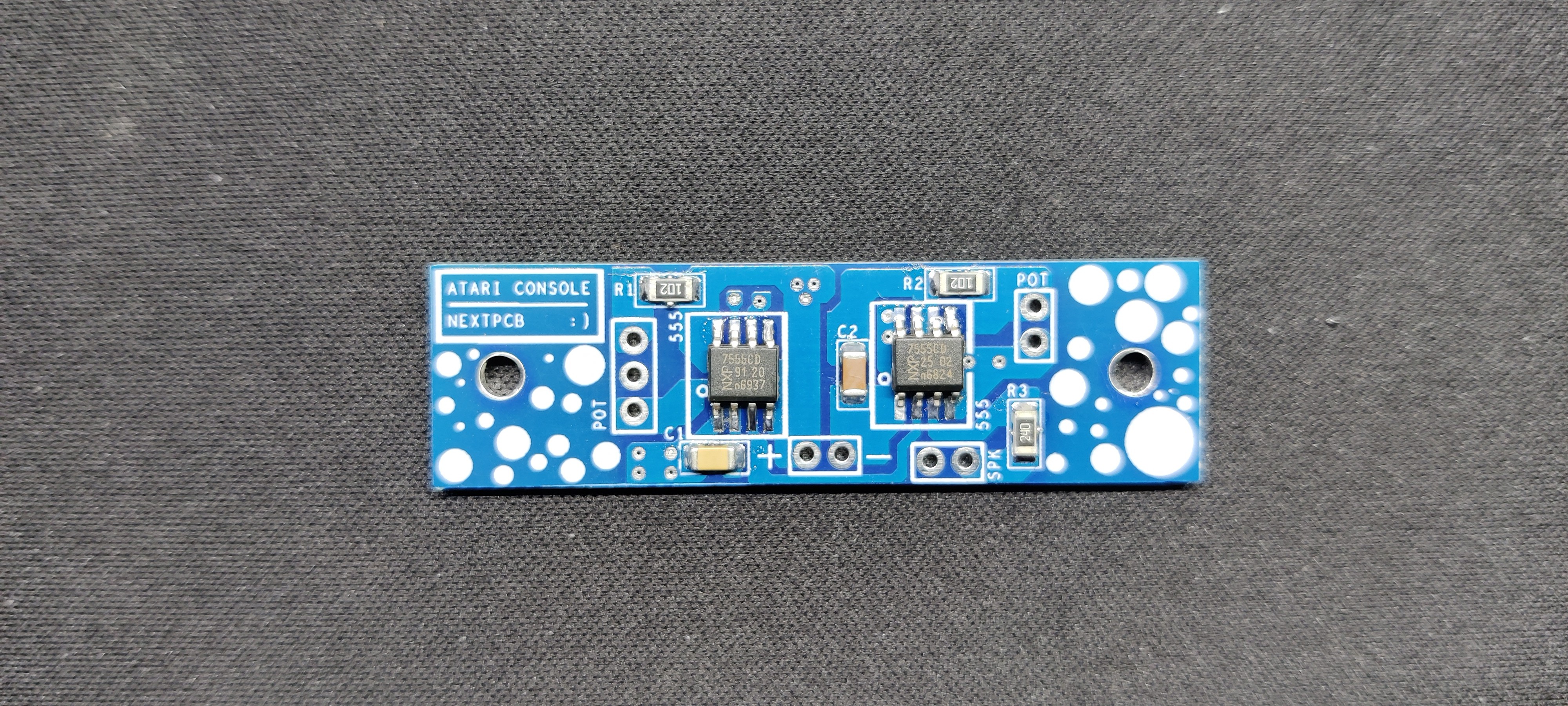
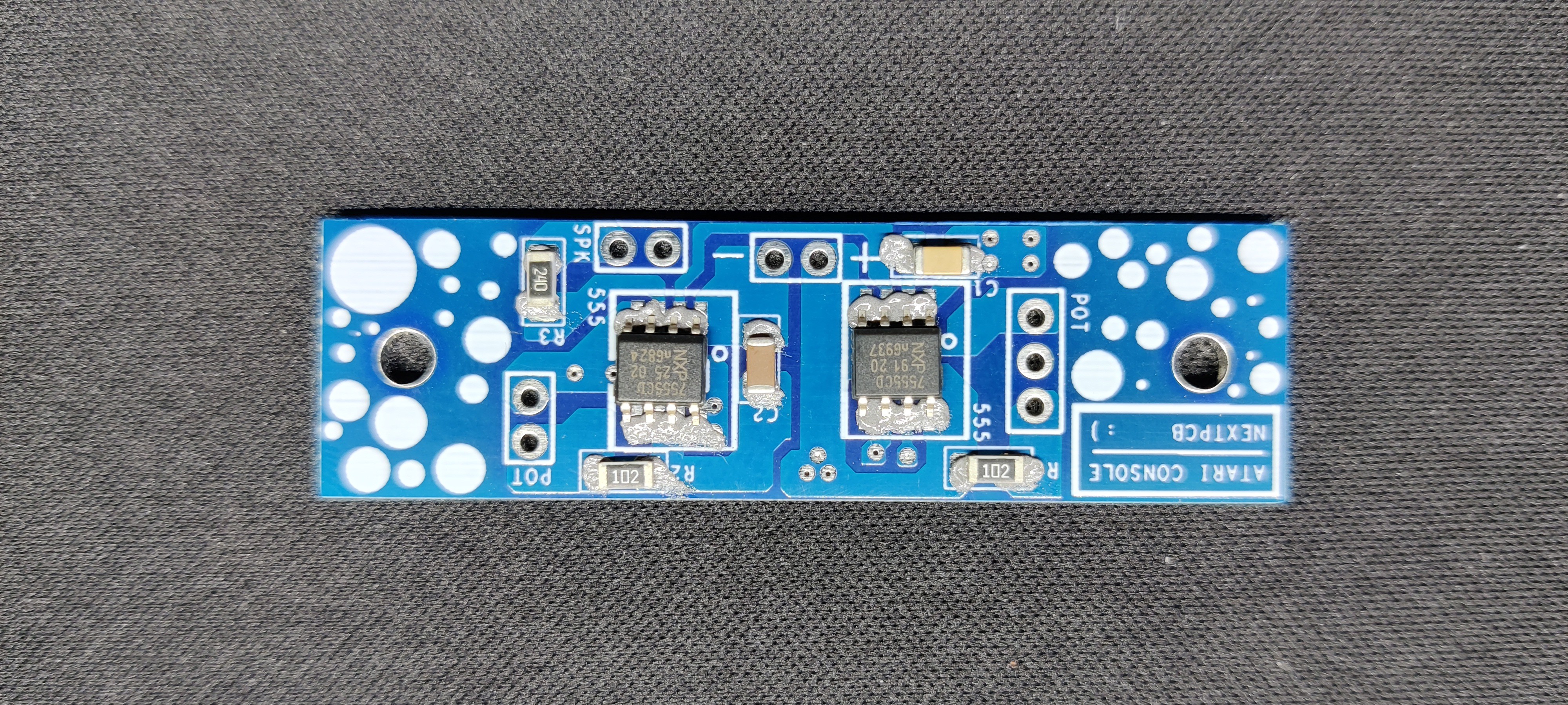
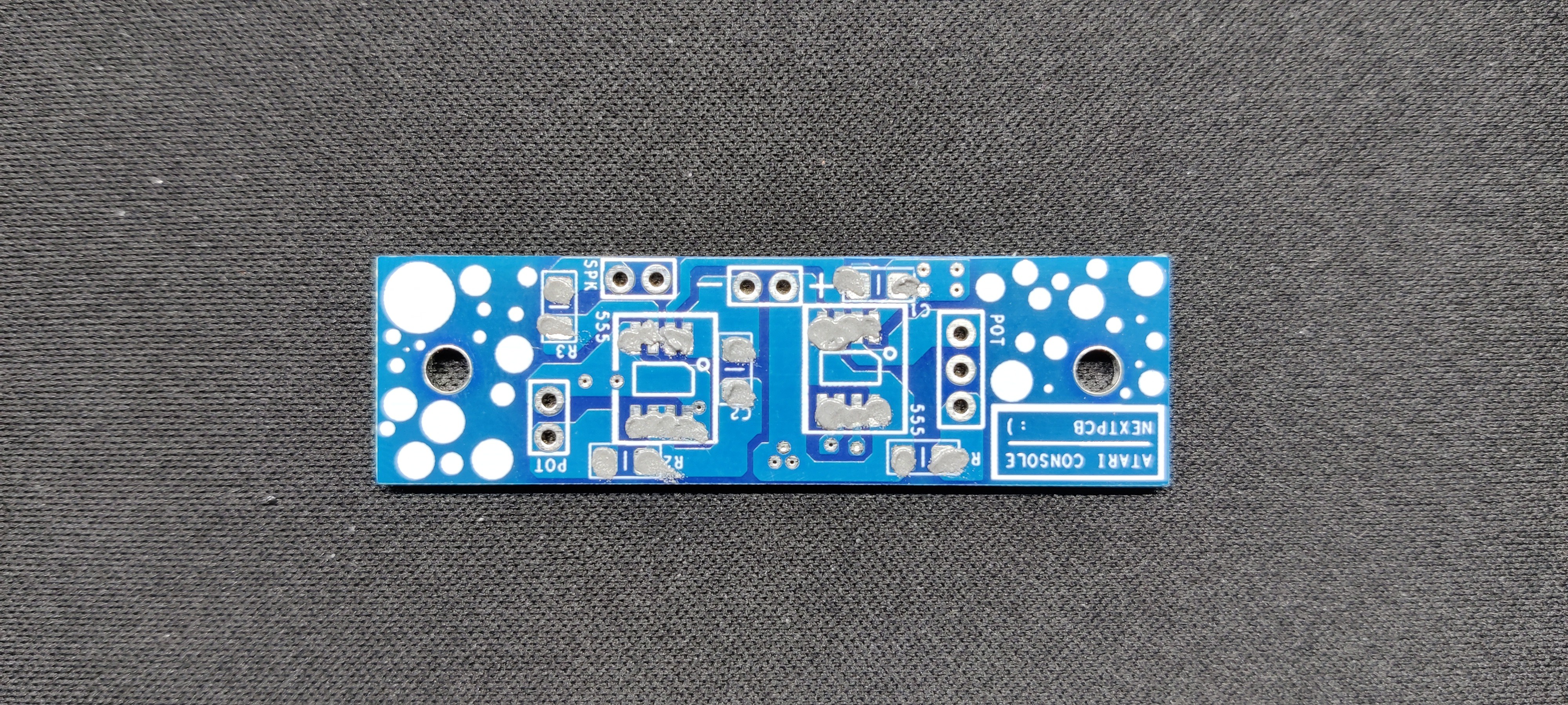
- First, we used a solder paste dispensing needle to apply solder paste (standard 37/63 Sn-Pb solder paste) to each component pad.
- Next, we pick and place each component onto their designated pad with the help of an ESD tweezer.
- The circuit is next placed on our PCB hotplate, which heats it from below up to the solder paste melting temperature. At this point, the components are connected to their pads as soon as the PCB achieves the solder paste melting temperature, in our case, 200 °C.
The circuit is now complete.
-
2Body Assembly
![]()
![]()
![]()
![]()
![]()
![]()
![]()
![]()
![]()
![]()
![]()
![]()
![]()
![]()
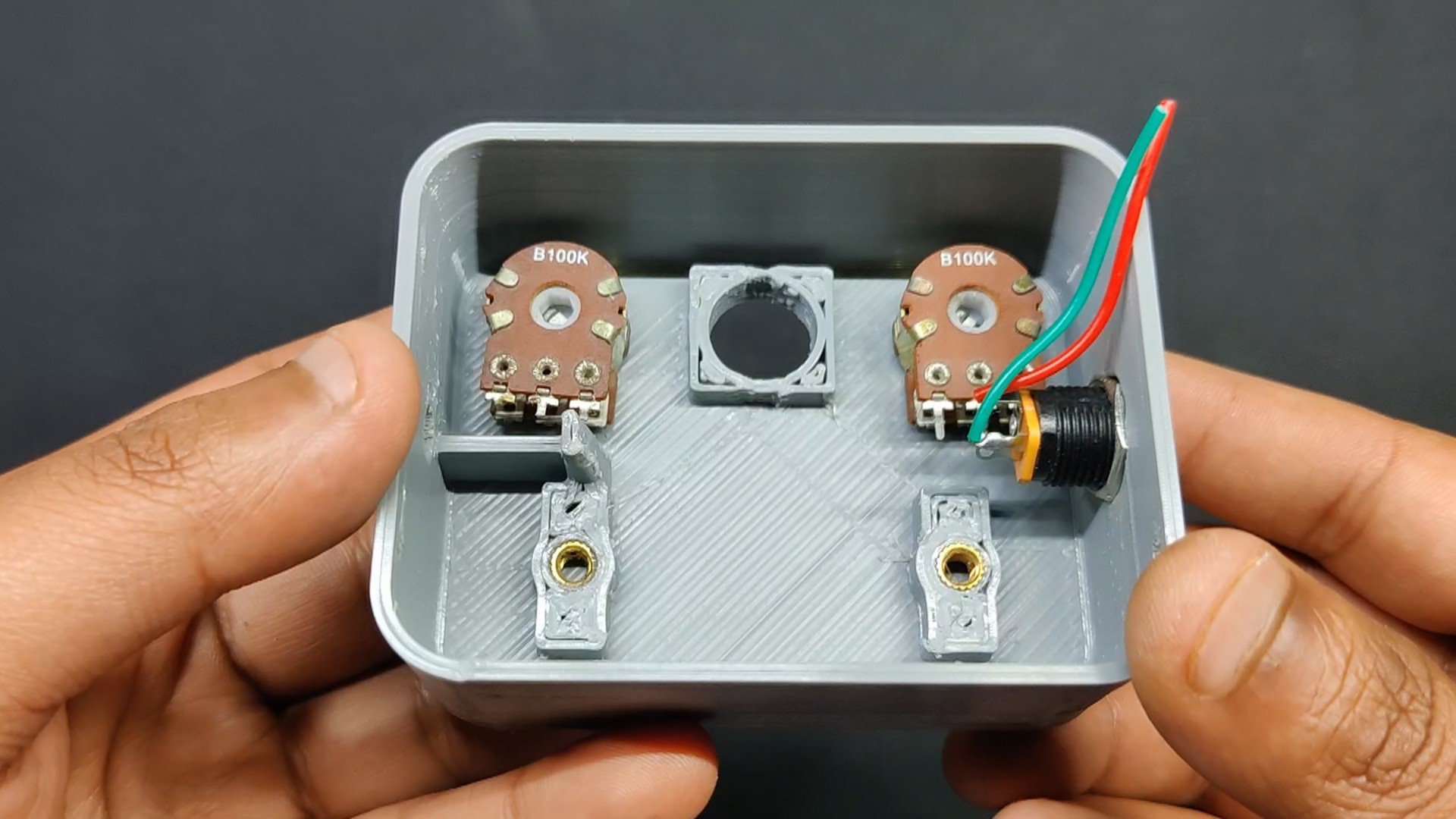
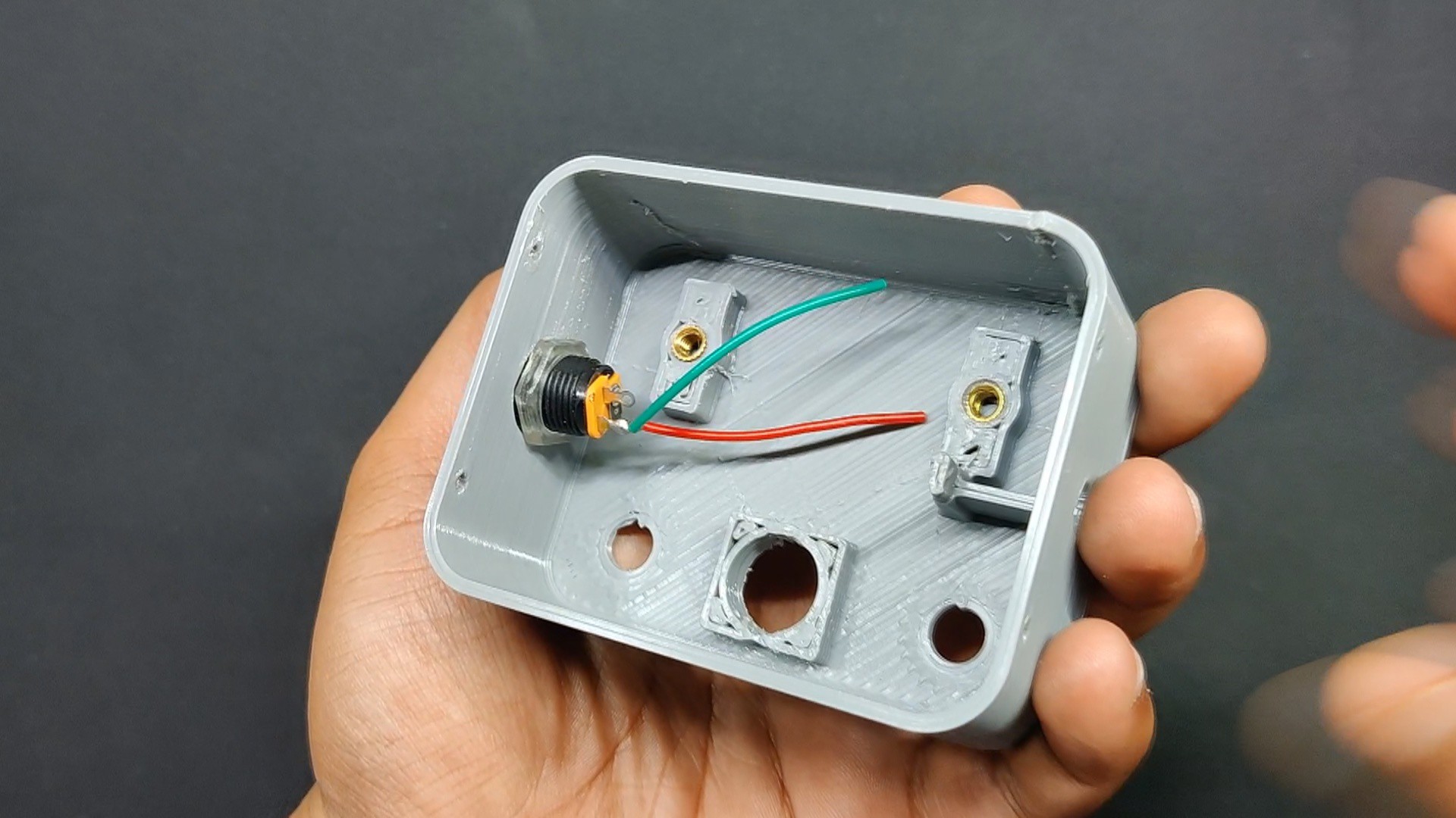
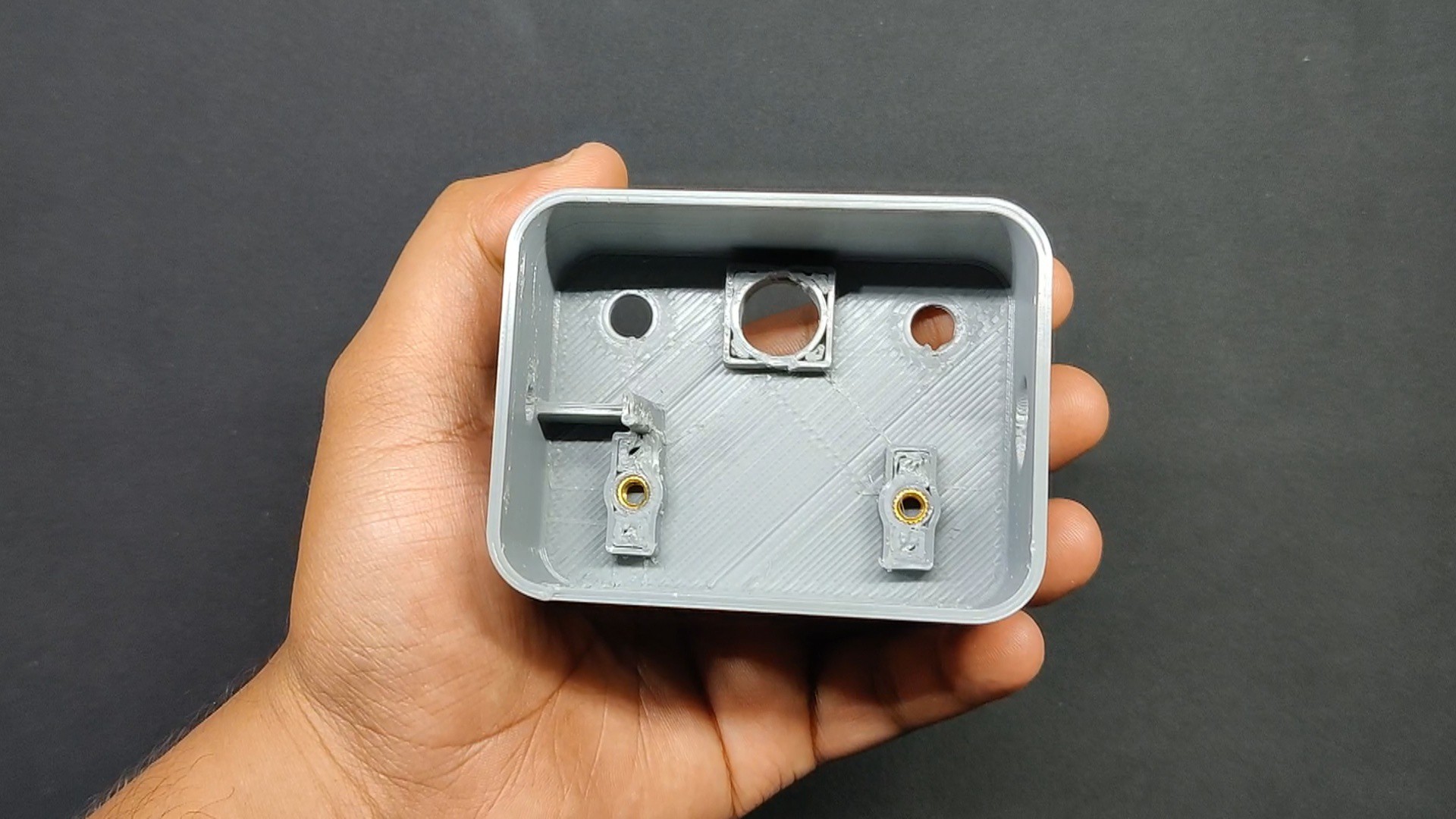
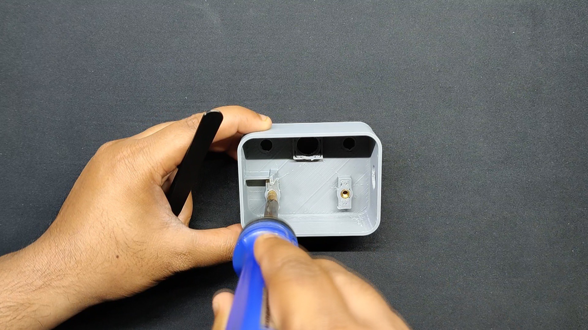
- In order to attach the circuit in place, the first step in the body assembly is to add threaded inserts to the holes that have been created inside the body. In this case, we are utilizing M2.5 threaded inserts.
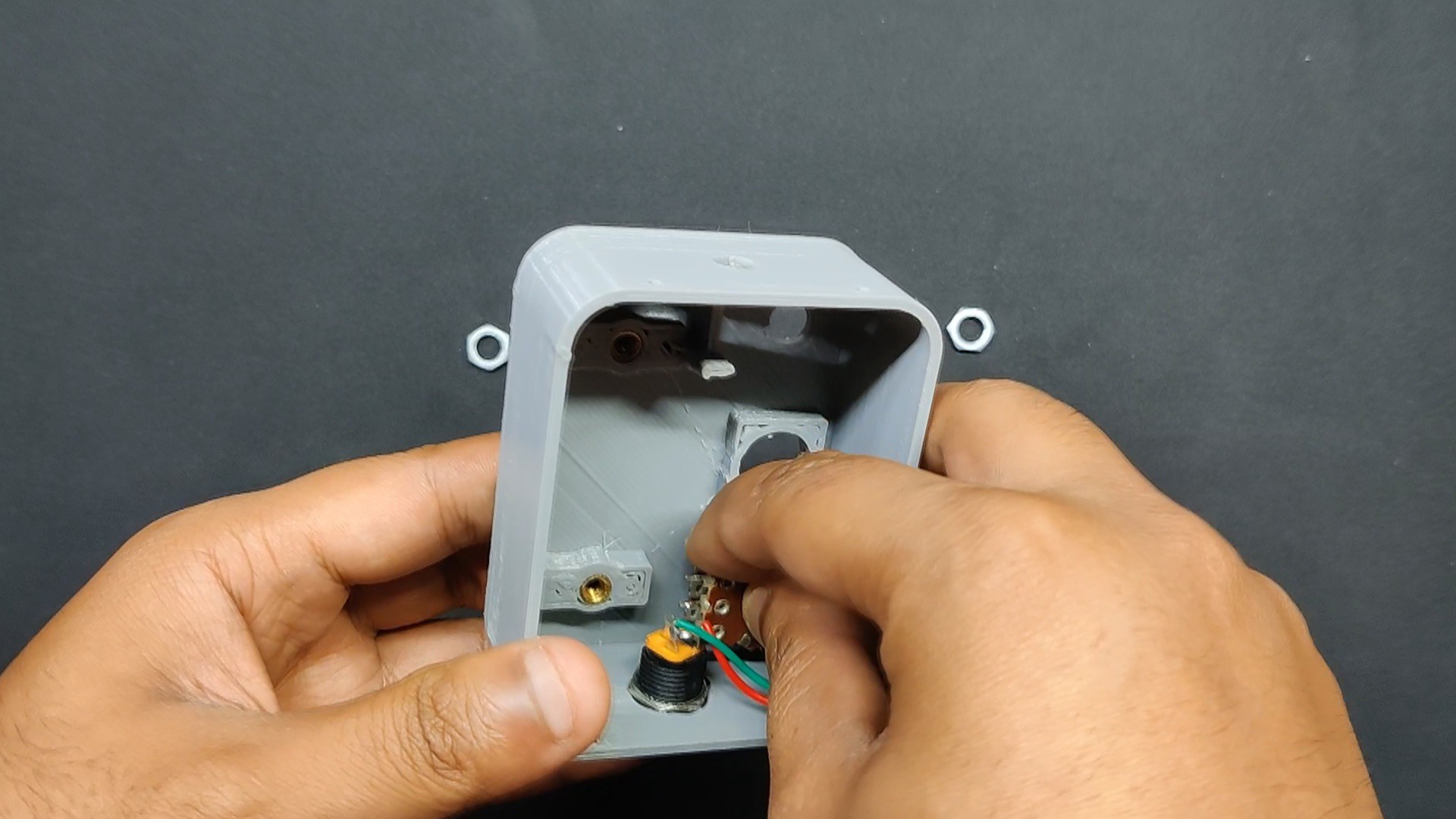
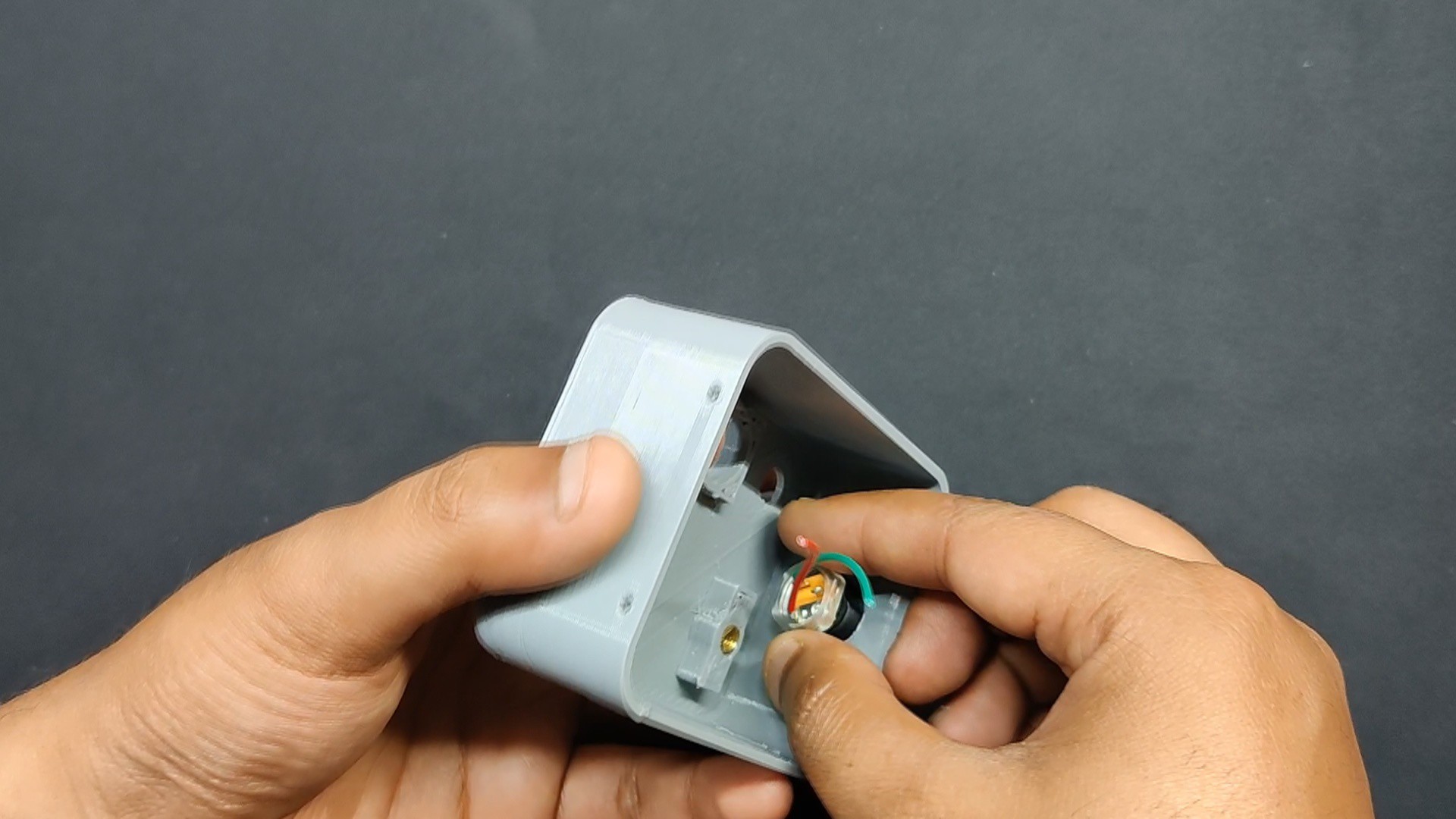
- Next, we insert the DC barrel jack on the body and tighten it using the included nut.
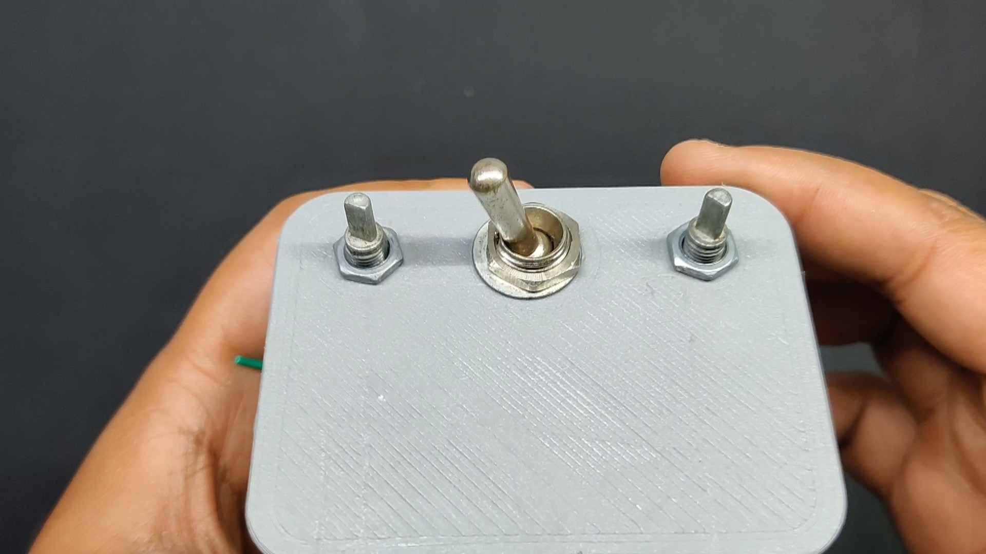
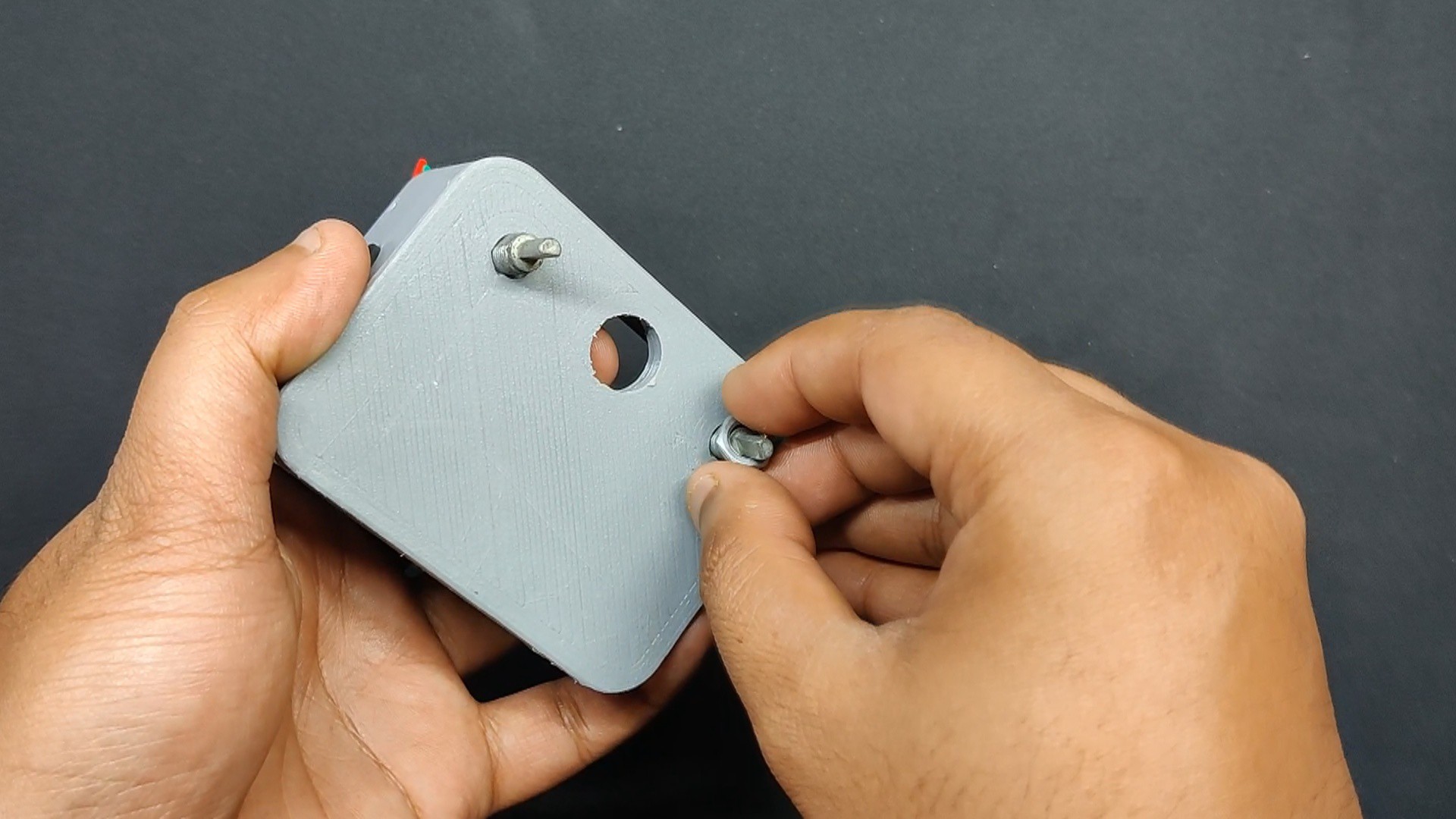
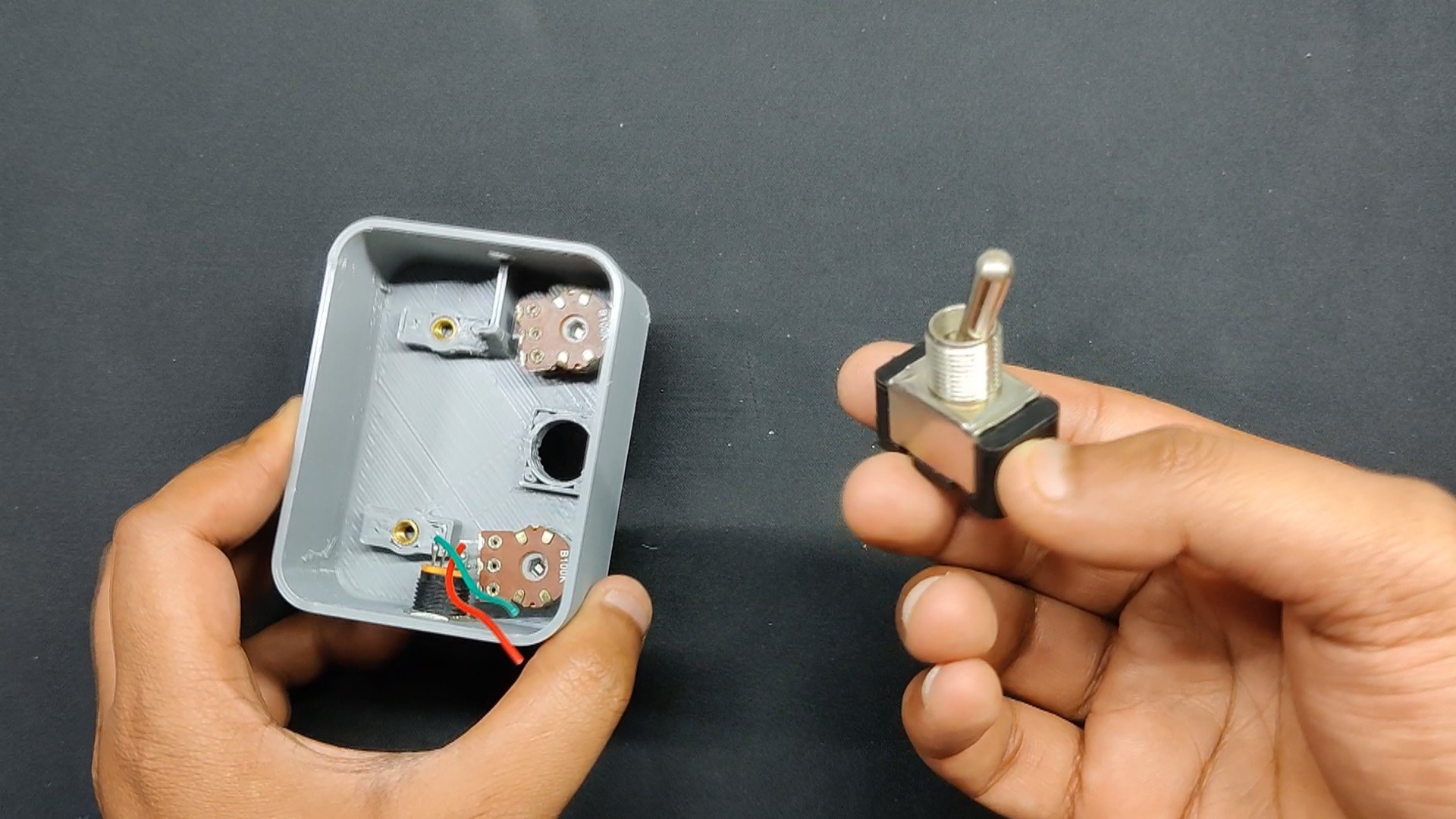
- The two potentiometers were then inserted into their designated locations and fastened with the included nut.
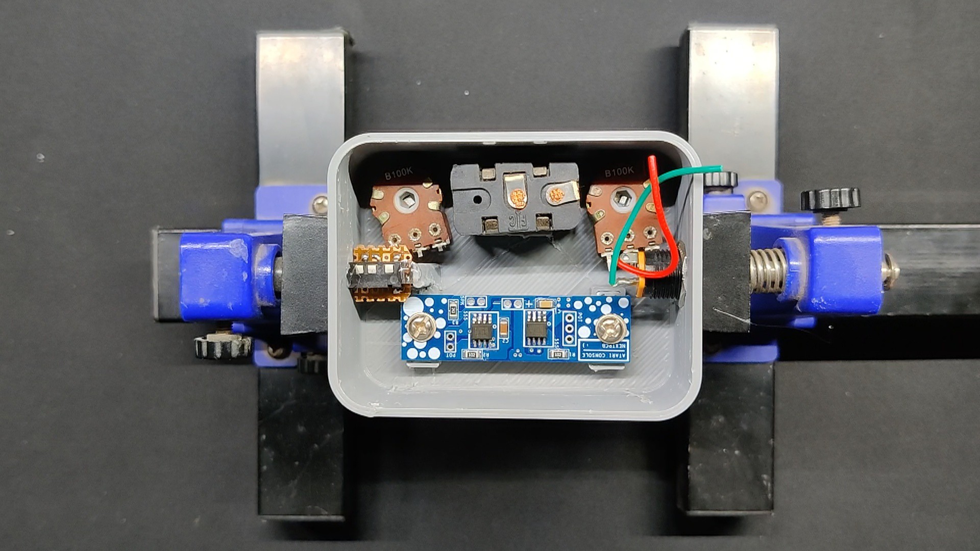
- In a similar manner, we inserted the toggle switch and used the included washer and nut to fasten it in place.
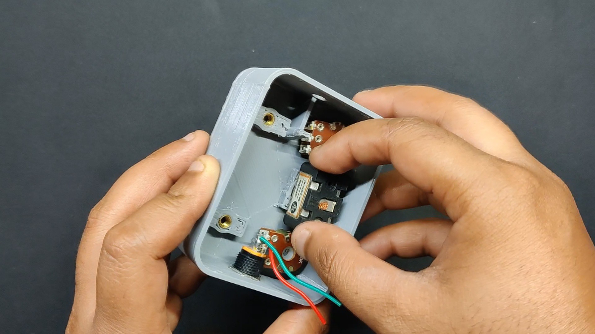
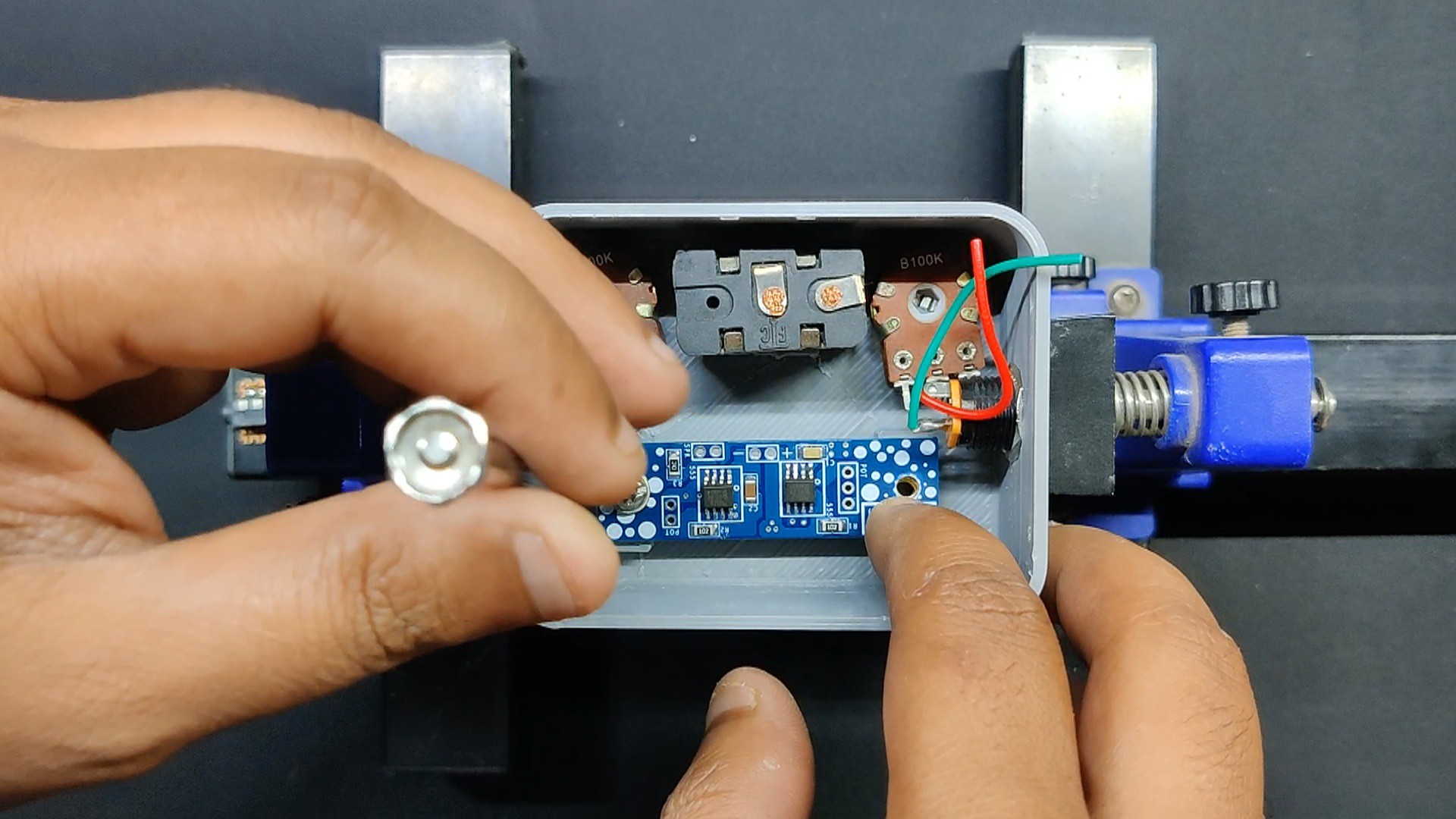
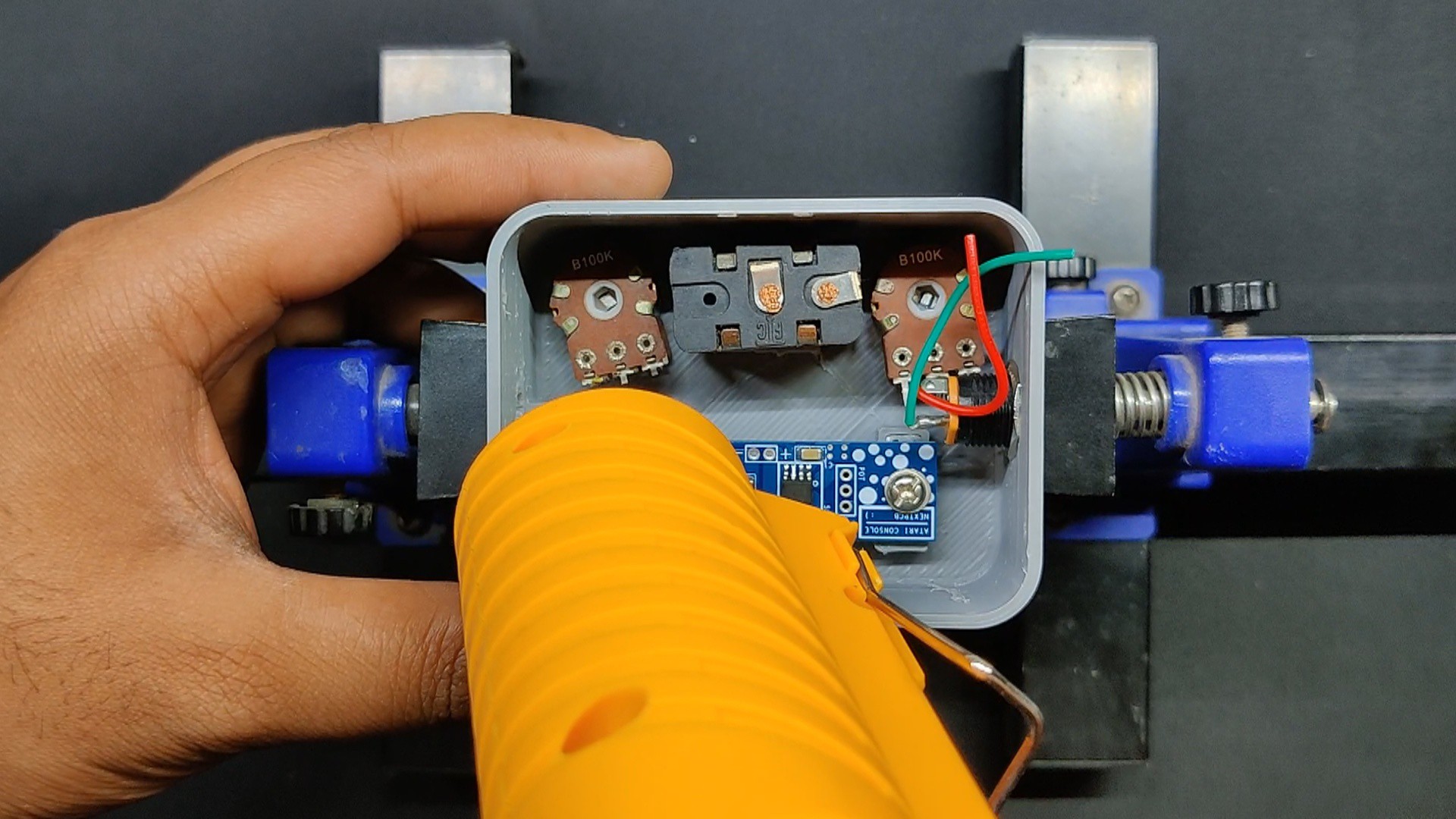
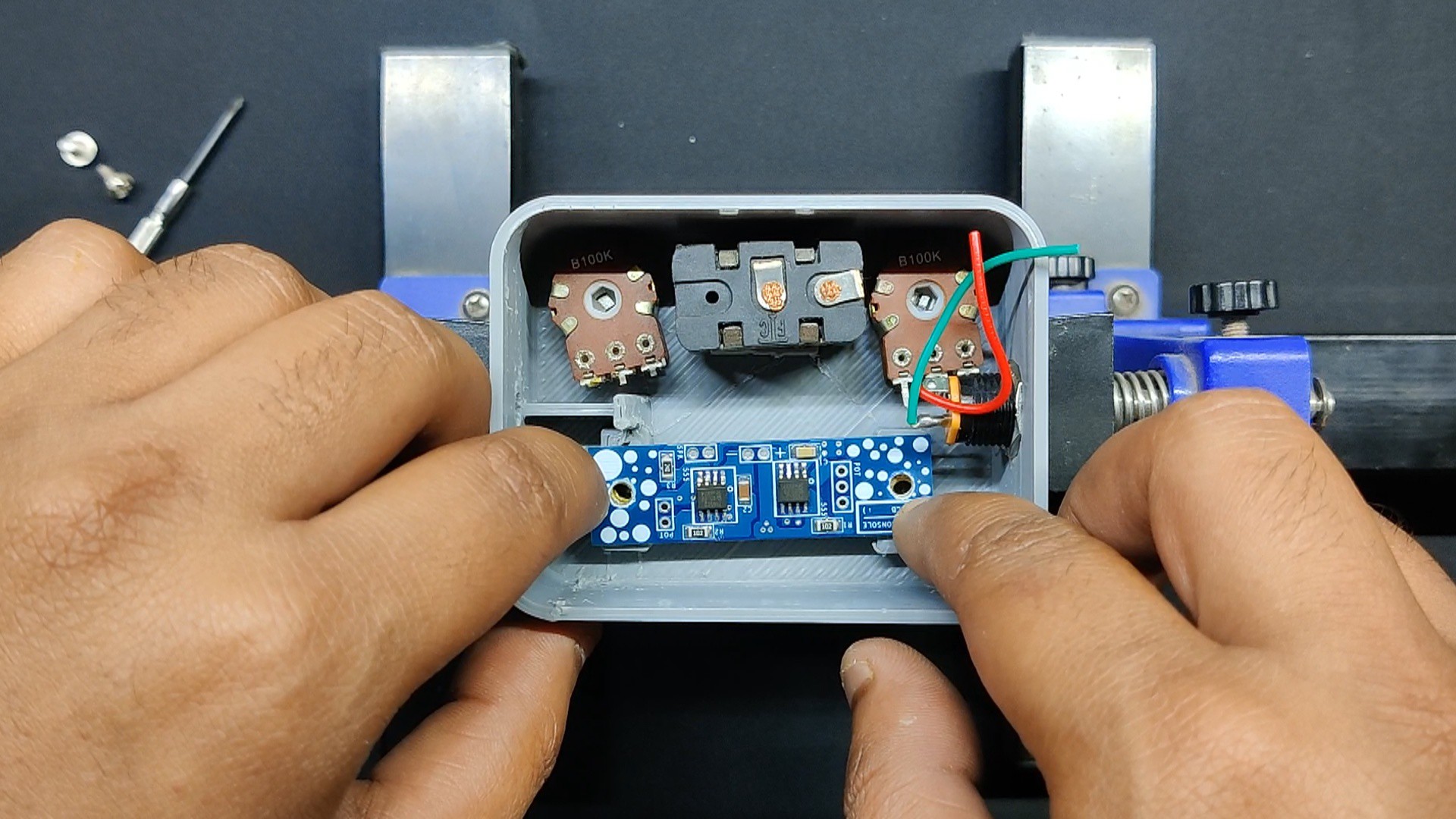
- The circuit is positioned over the mounting holes and fastened in place with two M2.5 bolts after the barrel jack, potentiometers, and switch have been mounted.
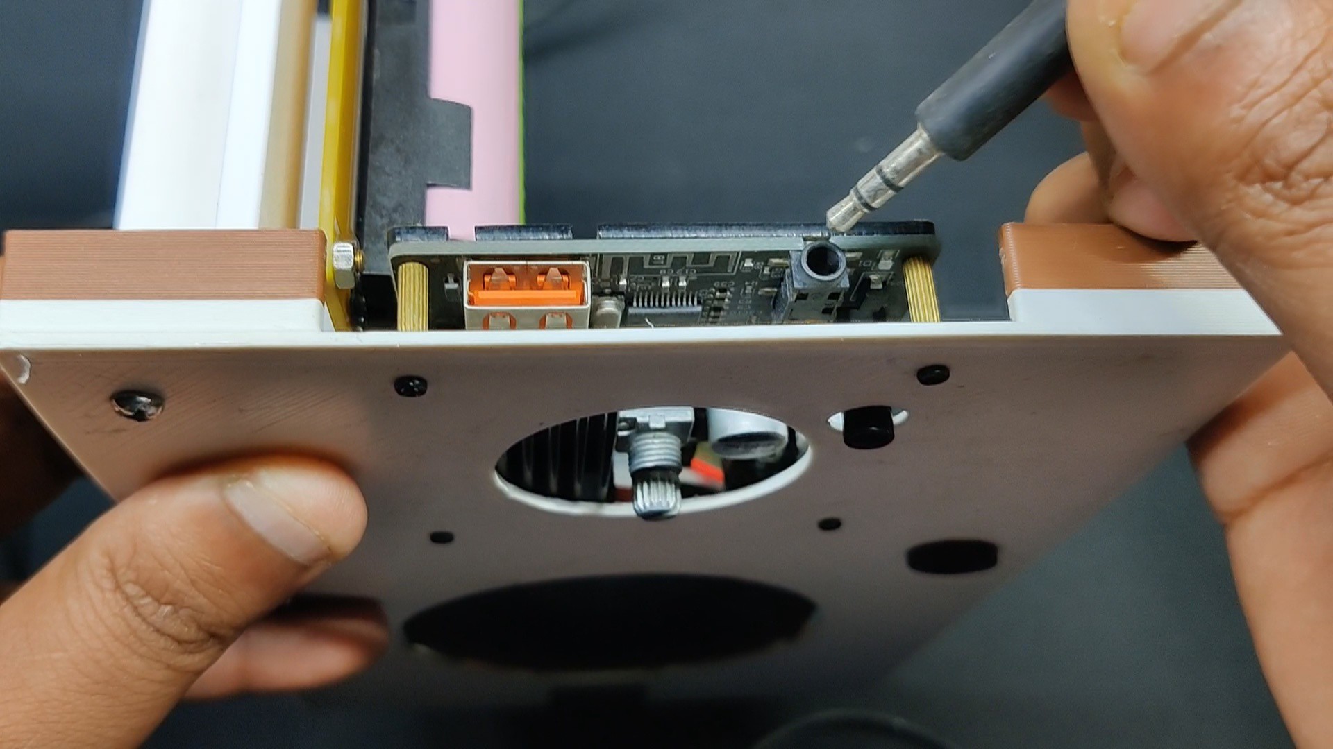
- To secure the audio jack in place, we placed a little bit of hot glue on the rib added within the body and then placed the audio jack board over it.
The basic assembly has been completed.
-
3Wiring
![]()
![]()
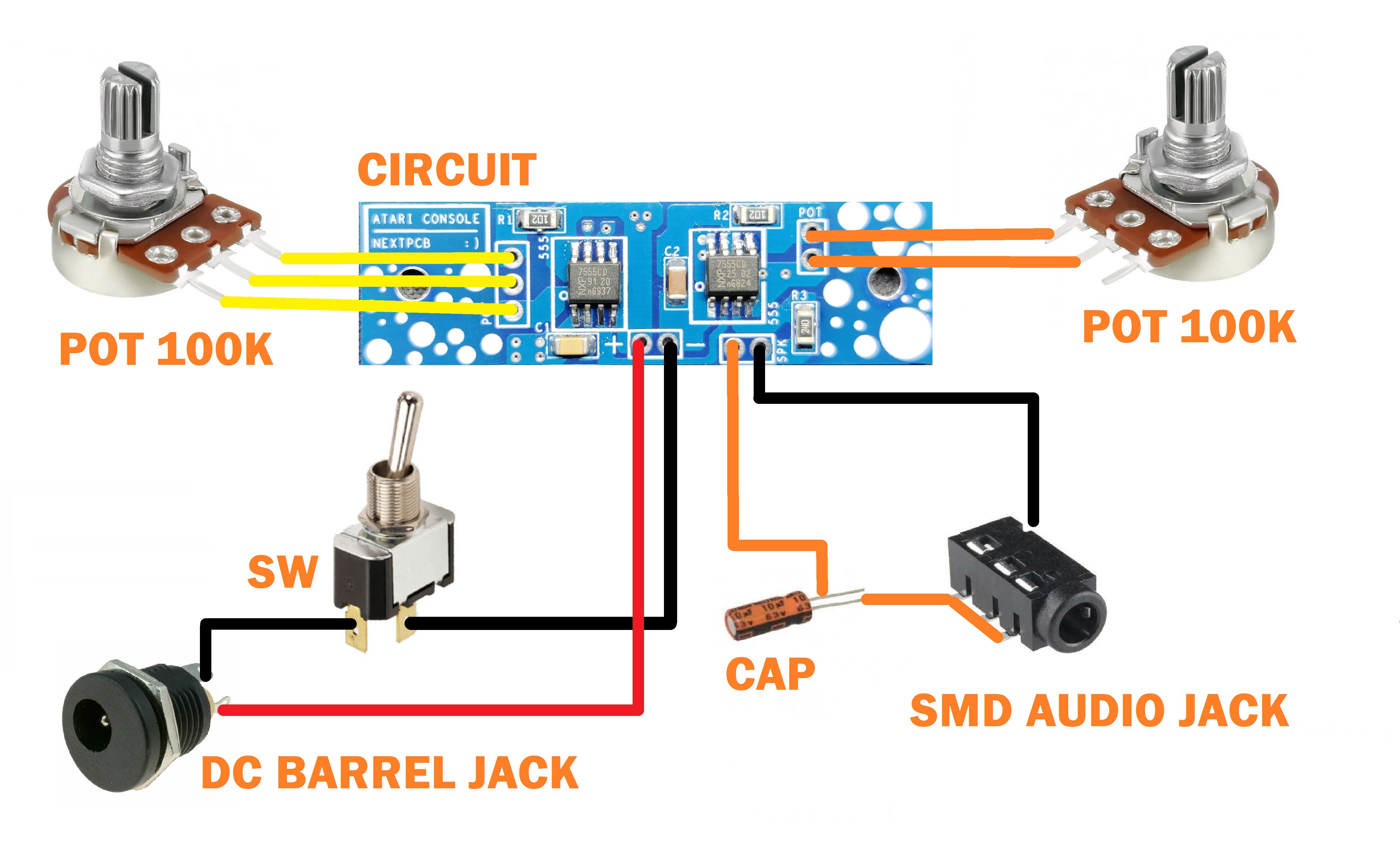
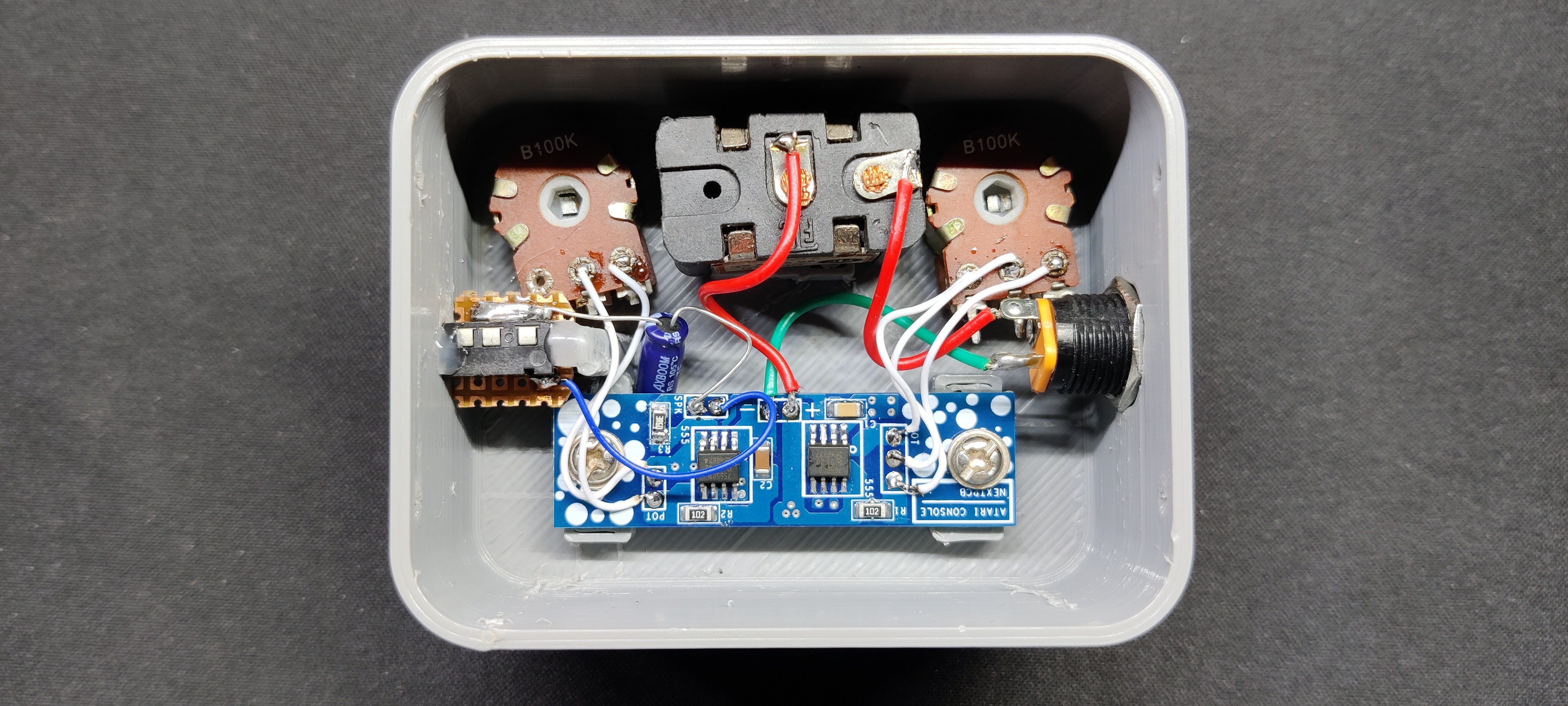
This circuit already had everything labeled on it, which made wiring really easy. Using the CON3 and CON2 provided on the circuit with the label POT, we first connected the two potentiometers.
Next, we connected the DC jack's negative to the switch terminal. The switch's other terminal is connected to the circuit is negative, which is likewise marked with a negative symbol.
Positive of DC jack will be connected with positive marked terminal of circuit.
We are utilizing an SMD Audio Jack for the output, and the speaker output's negative and ground are linked.
Furthermore, a 10uF 25V capacitor was attached to the speaker output's positive terminal. The capacitor's negative terminal is linked to the audio jack's positive terminal.
Check the wiring diagram for a better depiction
-
4Final Assembly
![]()
![]()
![]()
![]()
![]()
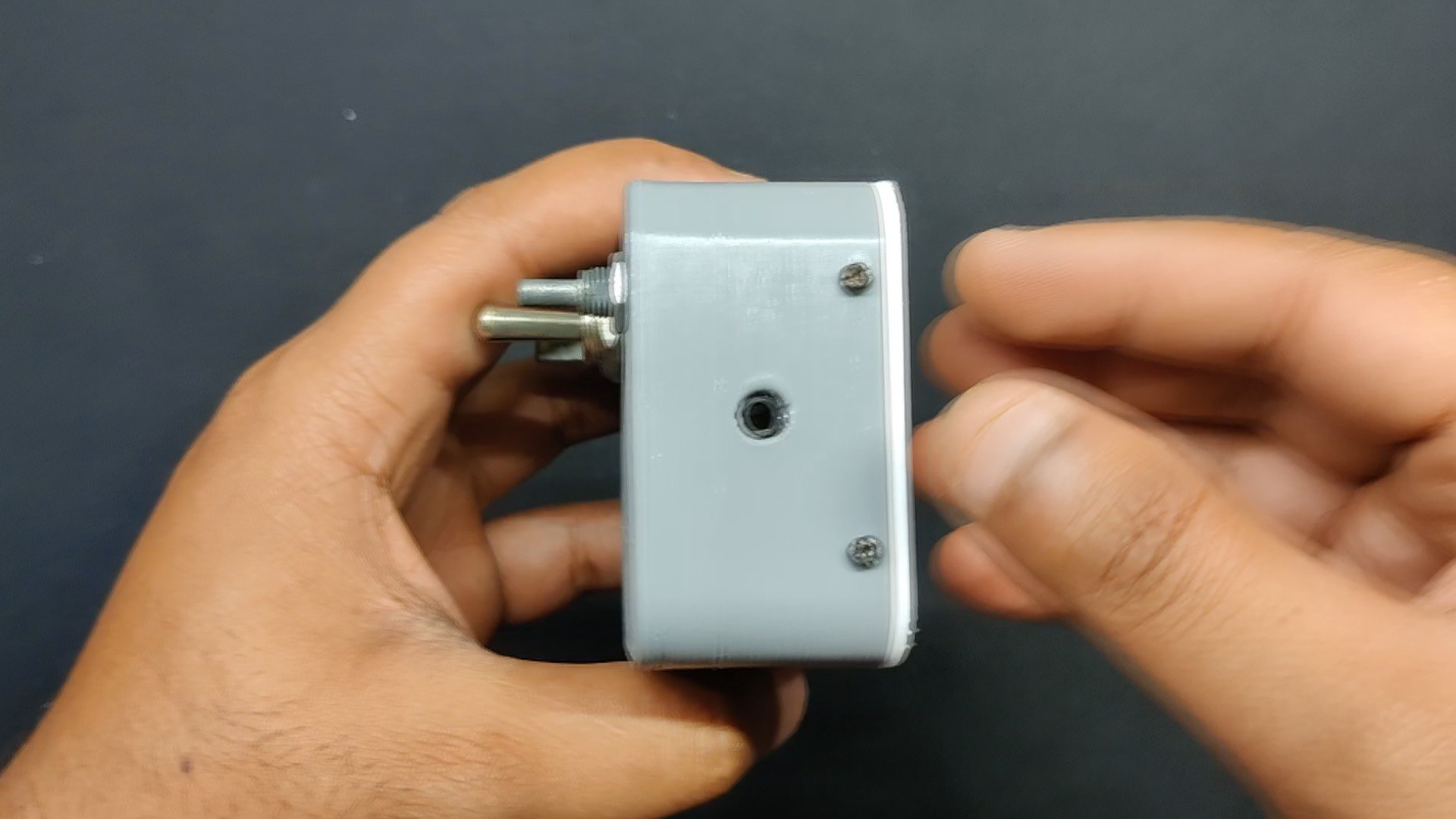
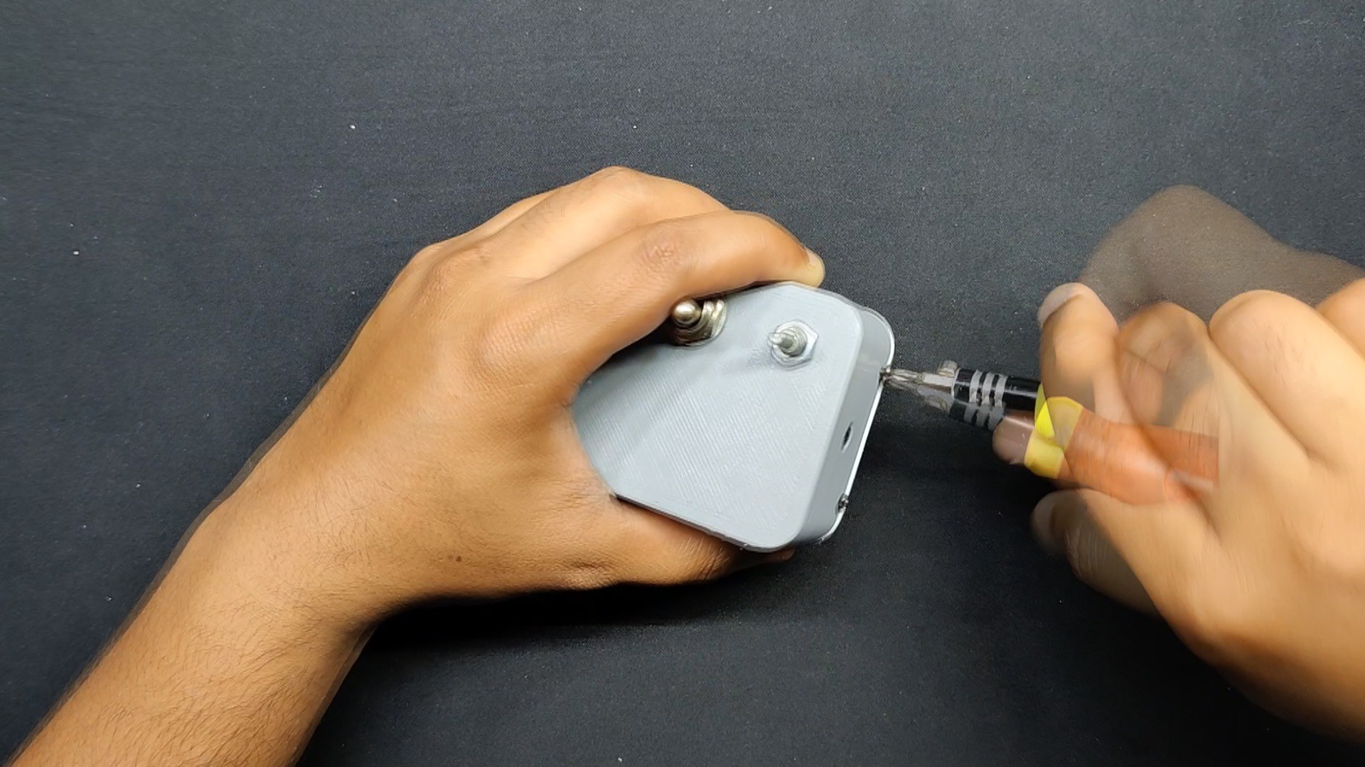
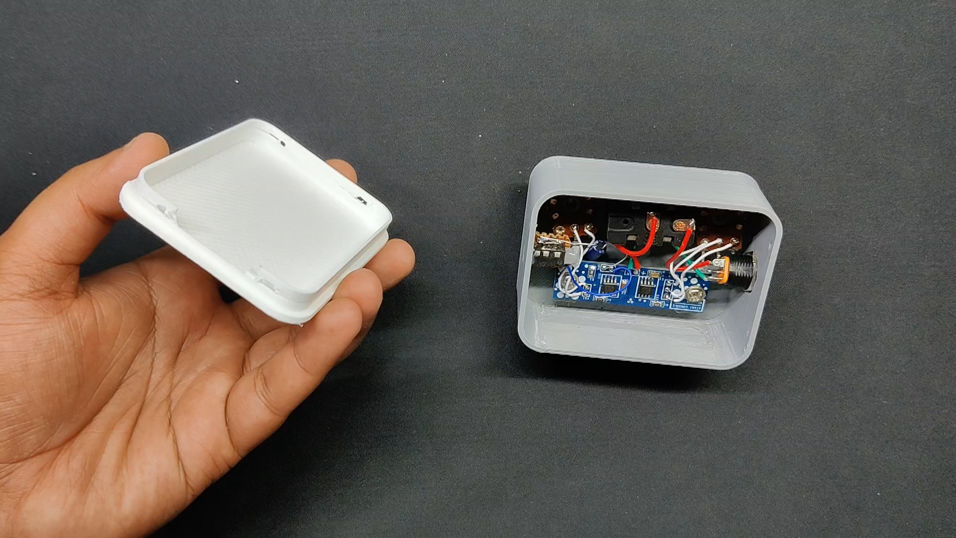
- We then installed a cover on the back side of the enclosure and fastened it to the main body using four M2 screws.
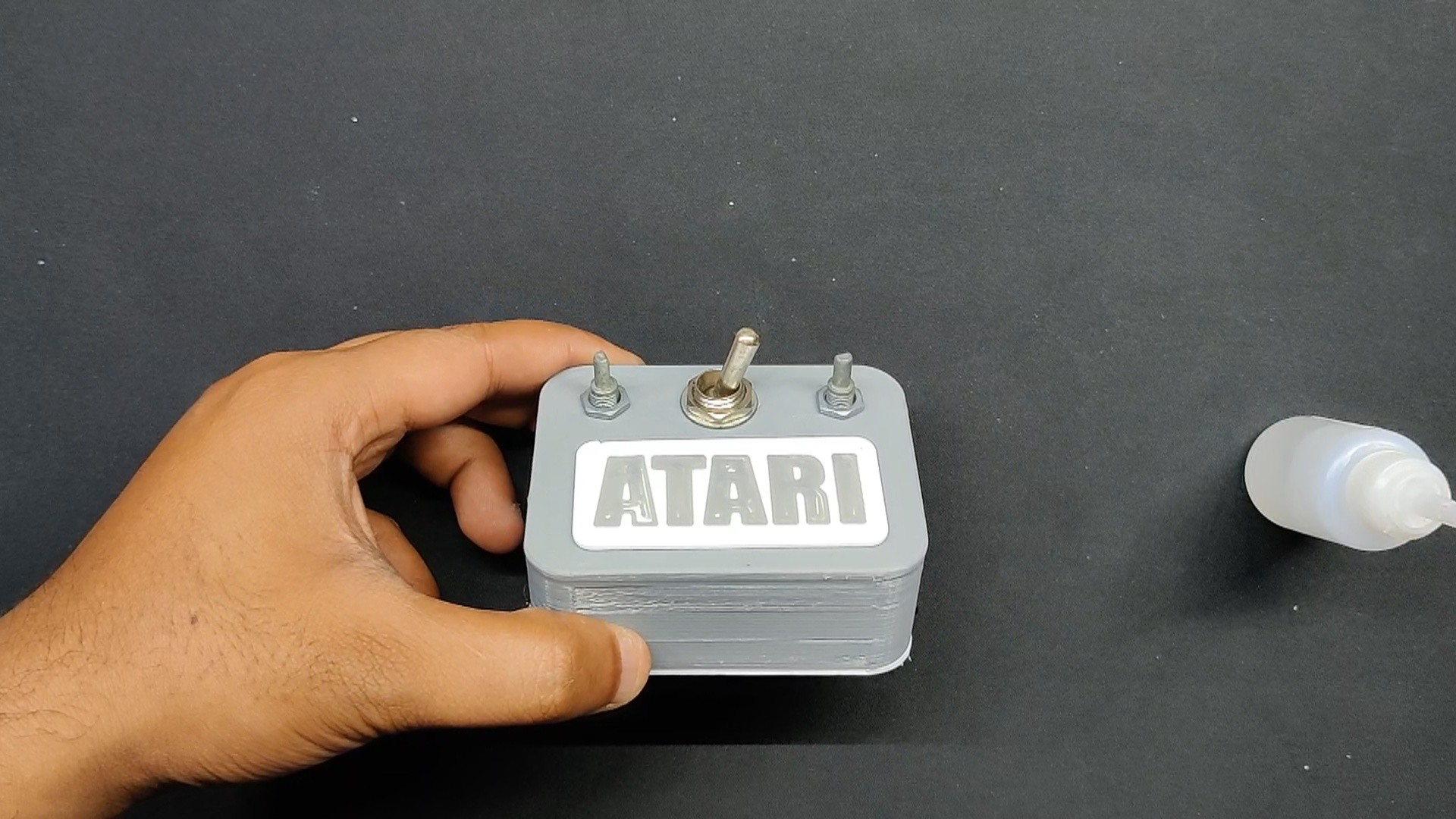
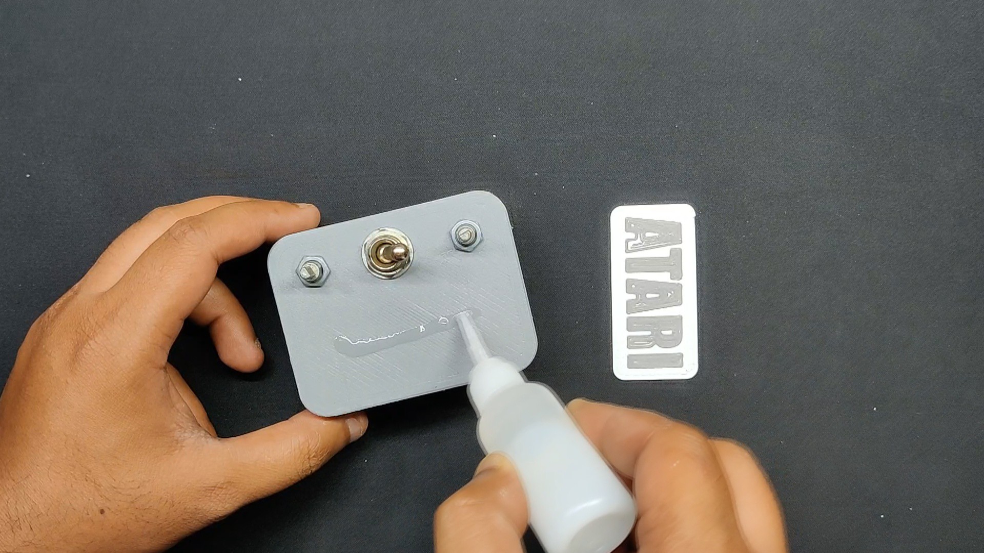
- To give it a final touch, we placed a tiny bit of super glue on the front side and positioned the Atari Nametag there. This will ensure that it remains permanently attached to the main body.
Assembly process is now completed.
-
5RESULT
![]()
![]()
Here's the result of this simple build, A functional synthesizer capable of generating many tunes, tones, and other altered sounds.
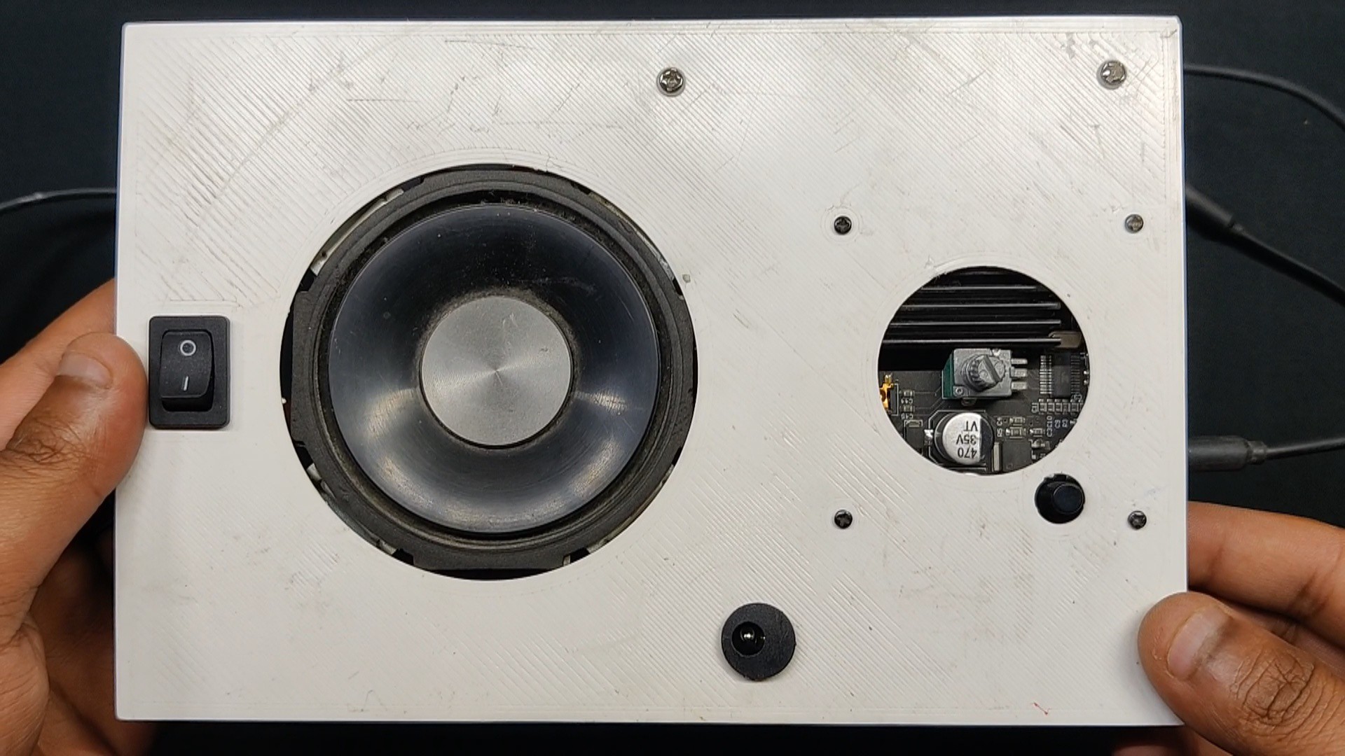
now here's a critical question- If the Atari Synth Box we just built does not have a speaker, how are we going to output sound?
We will be connecting our synth box to an external speaker with an audio jack input so that we can play audio.
We are utilizing a setup for this work that is based on the ZK-1002M Bluetooth Amplifier module, which you can check out from the link below. We utilized this arrangement in a prior project.
Here's the Video which you can checkout for listening to the sound of synth.
The following video demonstrates that the synth is functioning fairly well. It is obvious that the person using it is a novice, but someone with more musical experience might be able to create something really amazing with it.
With the exception of a centralized circuit that would contain all electronics in one tidy board and feature a speaker for output, this project was successful overall and does not require any further work.
If you are interested in this subject, have a look at a few of my synth projects.
https://www.hackster.io/Arnov_Sharma_makes/arduino-atari-punk-synth-2934e8
https://www.hackster.io/Arnov_Sharma_makes/neko-punk-synth-v2-d06f3e
https://www.hackster.io/Arnov_Sharma_makes/atari-punk-synth-v2-8b9dd3
Special thanks to HQ NextPCB for providing components that I've used in this project, check them out for getting all sorts of PCB or PCBA-related services for less cost.
Thanks and I will be back with a new project soon.
Atari Synth Box
Made the popular Atari Synth dual 555 timer based Tone generator from-scratch.
 Arnov Sharma
Discussions
Become a Hackaday.io Member
Create an account to leave a comment. Already have an account? Log In.