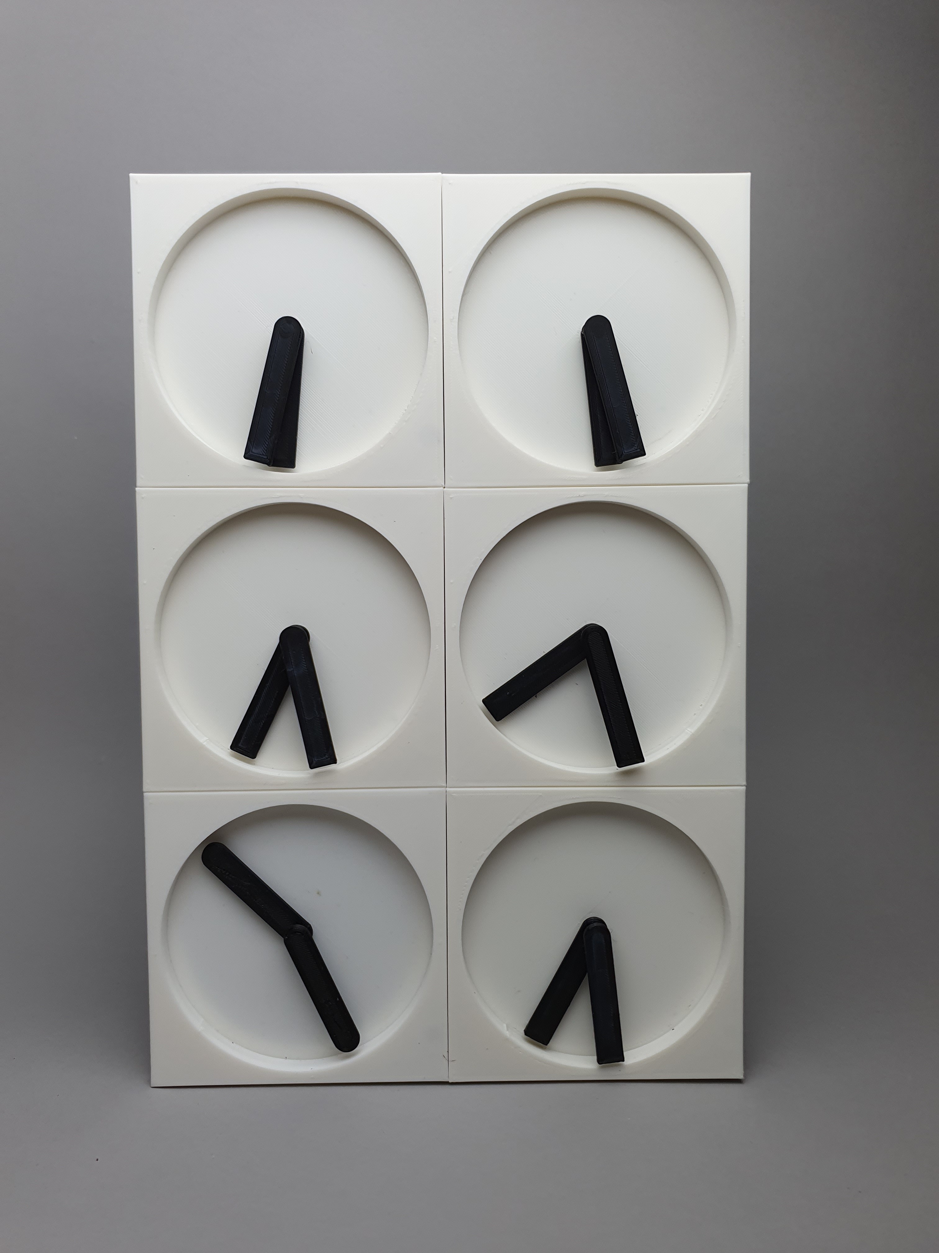
-
Of course we need some LEDs
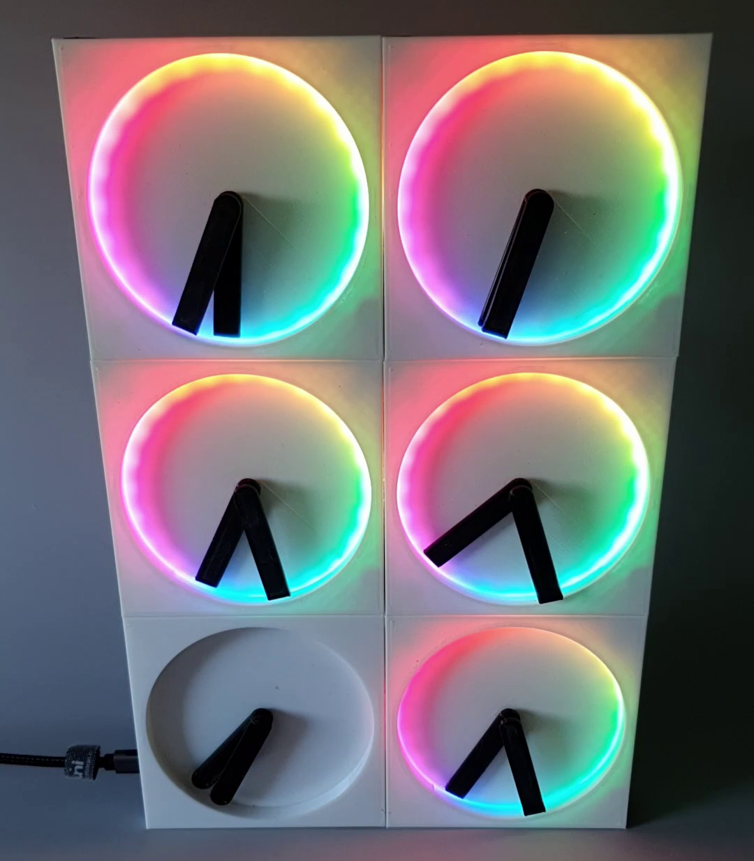
08/05/2024 at 21:11 • 0 commentsI wanted to have some kind of backlight so that it would be possible to read the display aat night as well. Therefore I integrated a ring of LEDs at the outer boarder of the front side of the PCB. With the help of a 3D printed light guide the LED light is then led through the outer border of the "clock circle". In the video you can see the initial start up animation that is displayed when the modules boot up.
![]()
-
Power Delivery via the FUSB302
08/05/2024 at 21:10 • 0 commentsI really like the concept and idea behind Power Delivery. Thats why I try to use it in my projects as well.
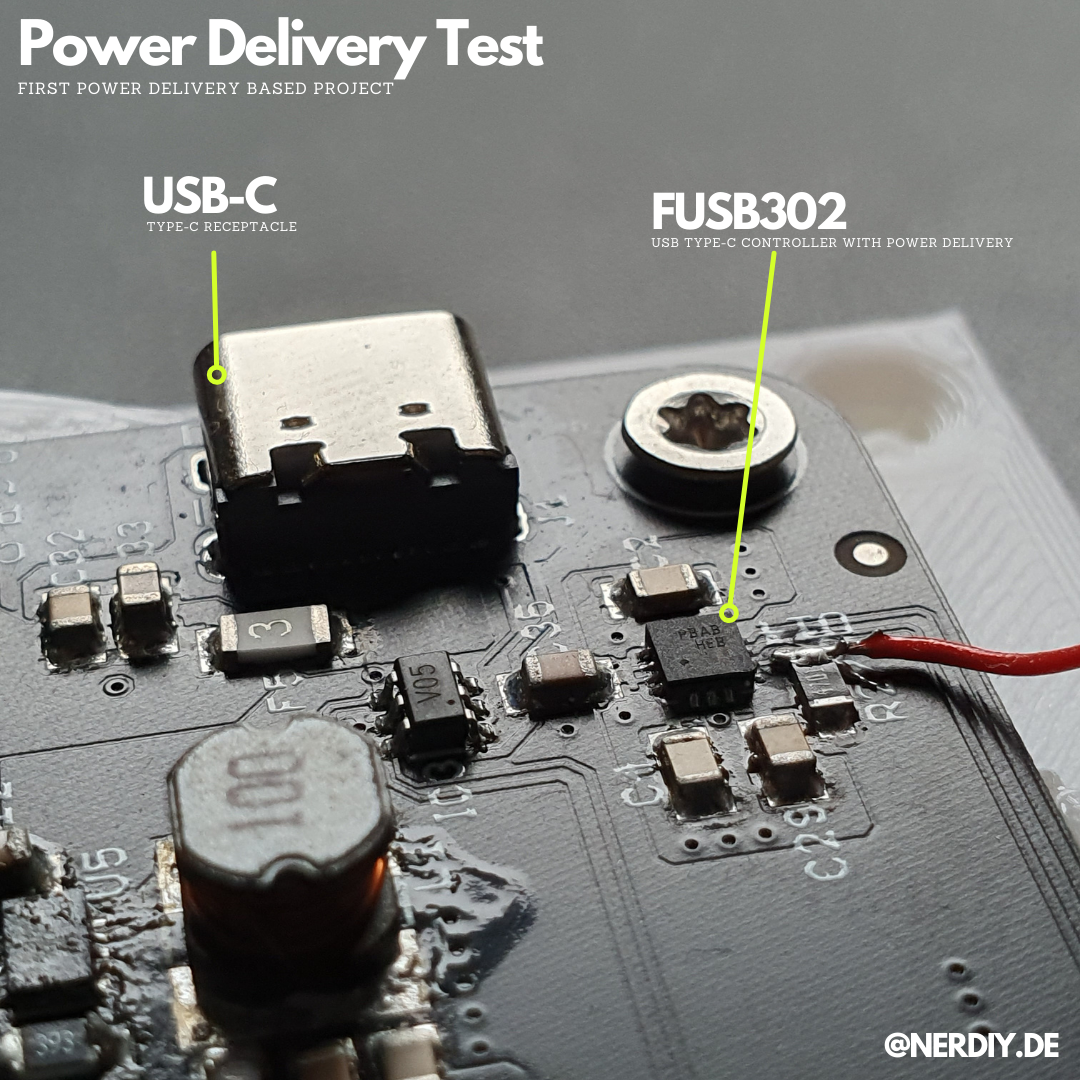
To gain some first experiences I integrated a FUSB302 Power Delivery phy into my PCB. It communicates over I2C with the ESP32 on the master module and triggers the highest available PD profile to keep the voltage drop on the inter-module-bus as low as possible.
![]()
-
PCB Version 1.7 - Current project state
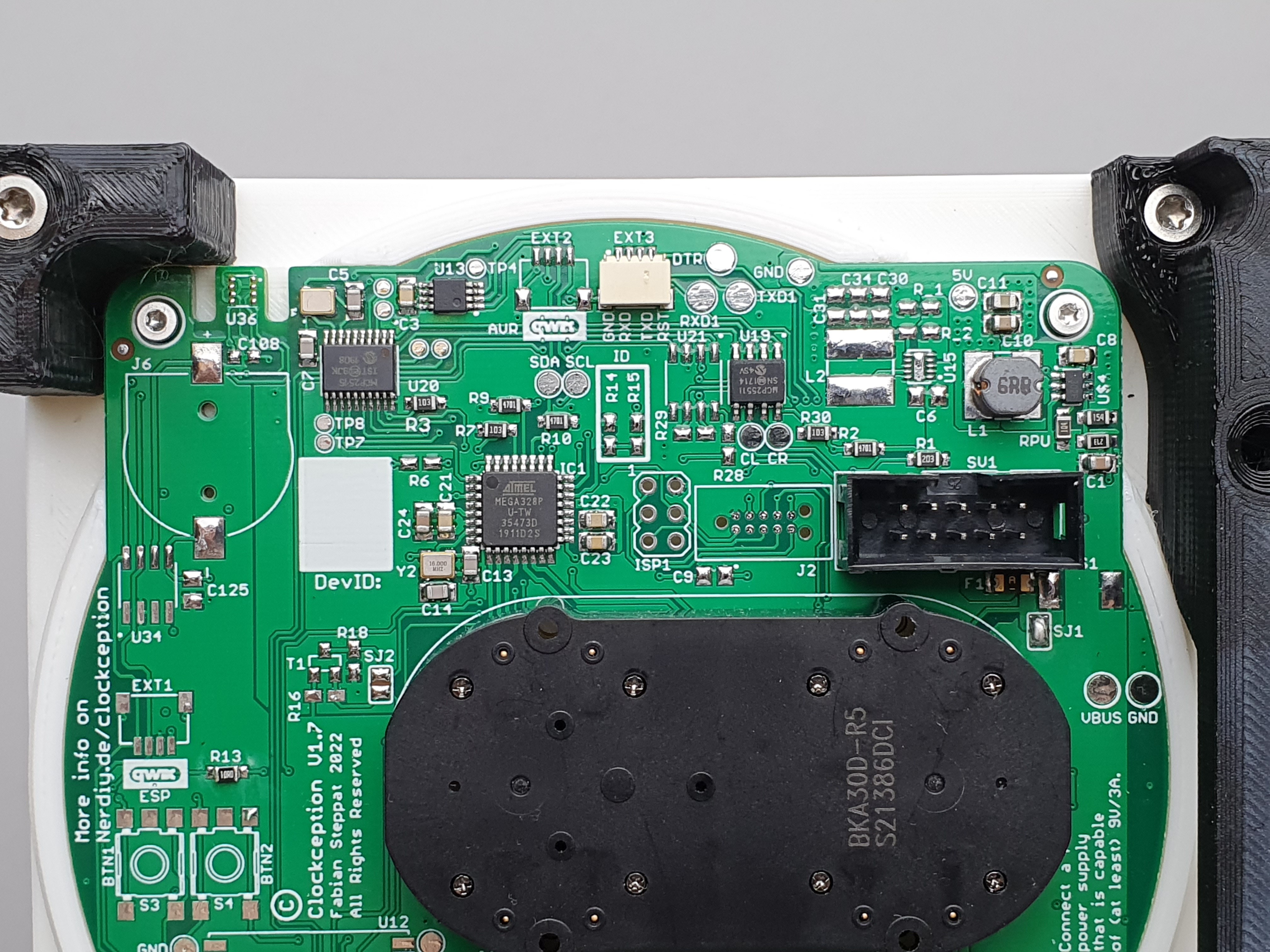
08/05/2024 at 21:10 • 0 commentsBelow you can see some details of the current PCB version.
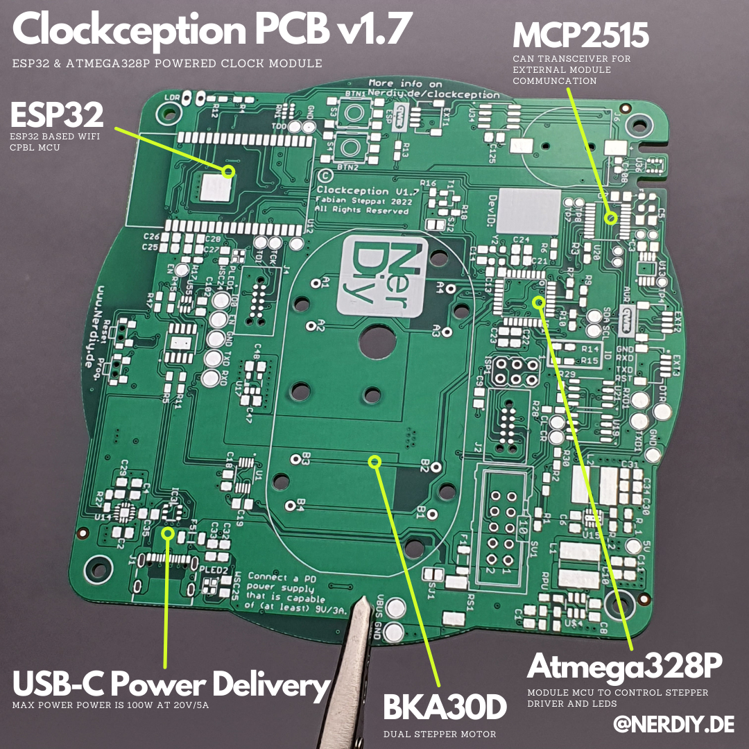
![]()
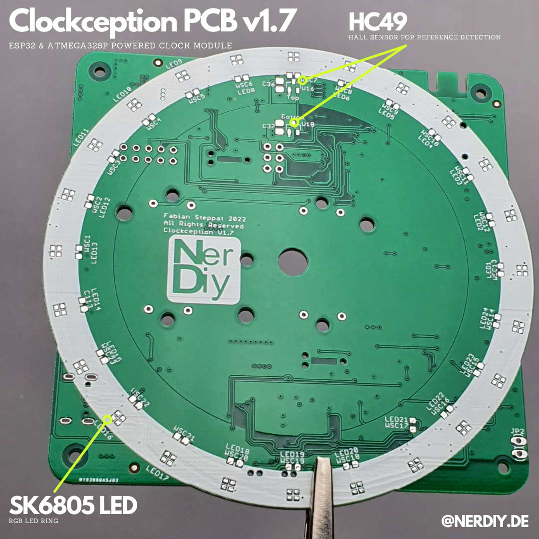
On the front side of the PCB you can see the landing pads for the SK6812 LEDs and the HC49 hall sensors. I used white silk screen around the led ring to increase the light reflection in that area. ![]()
![]()
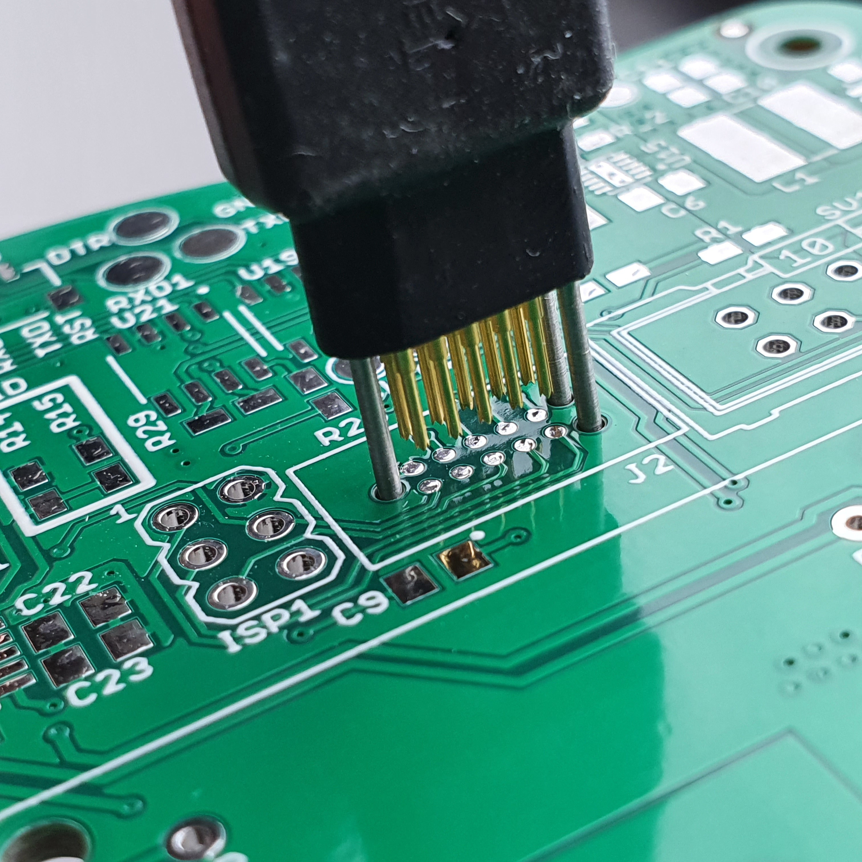
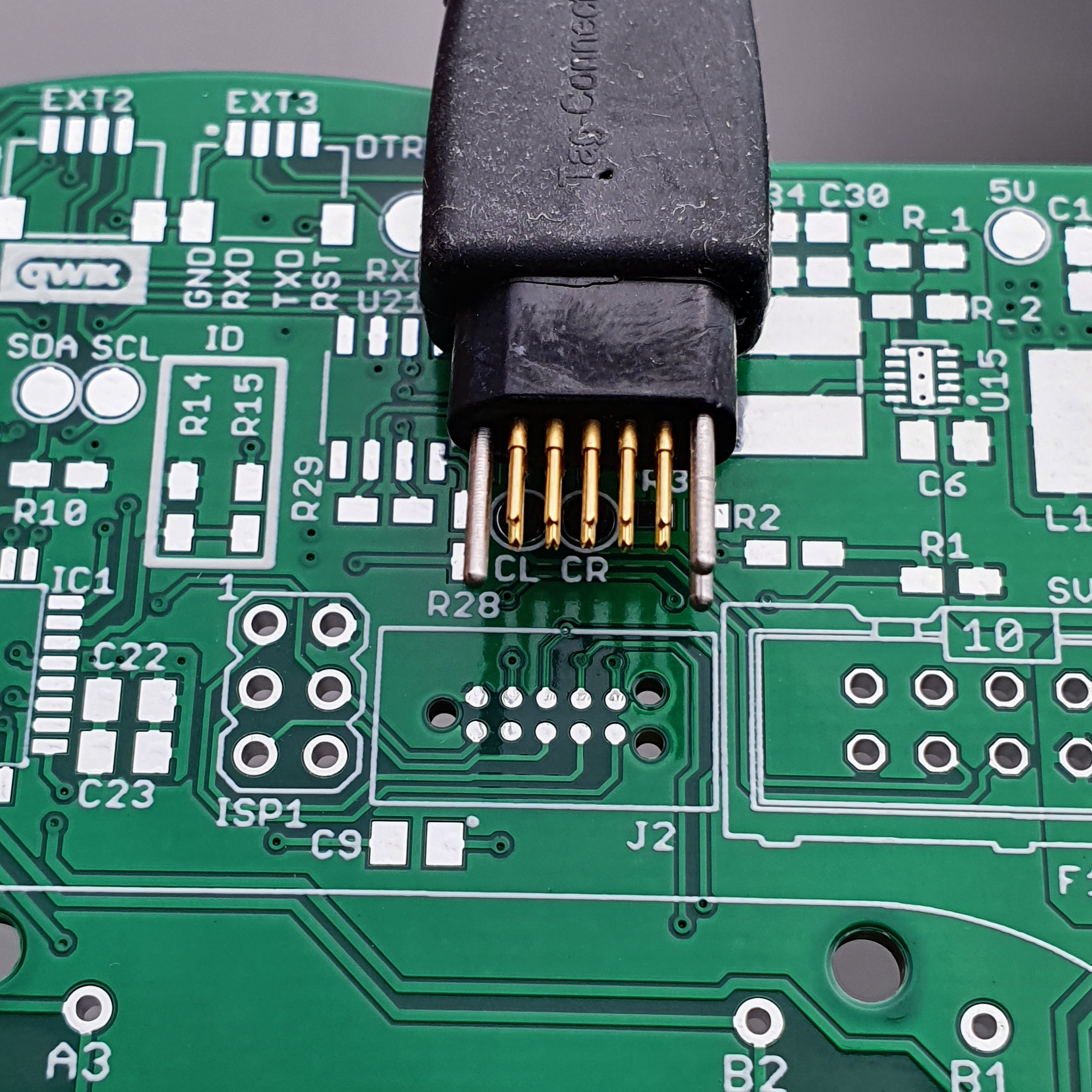
With this iteration I also introduced a pogo pin based flashing connector. This way it should be easier to flash a high amount of PCBs and save components. ![]()
![]()
![]()
![]()
![]()
-
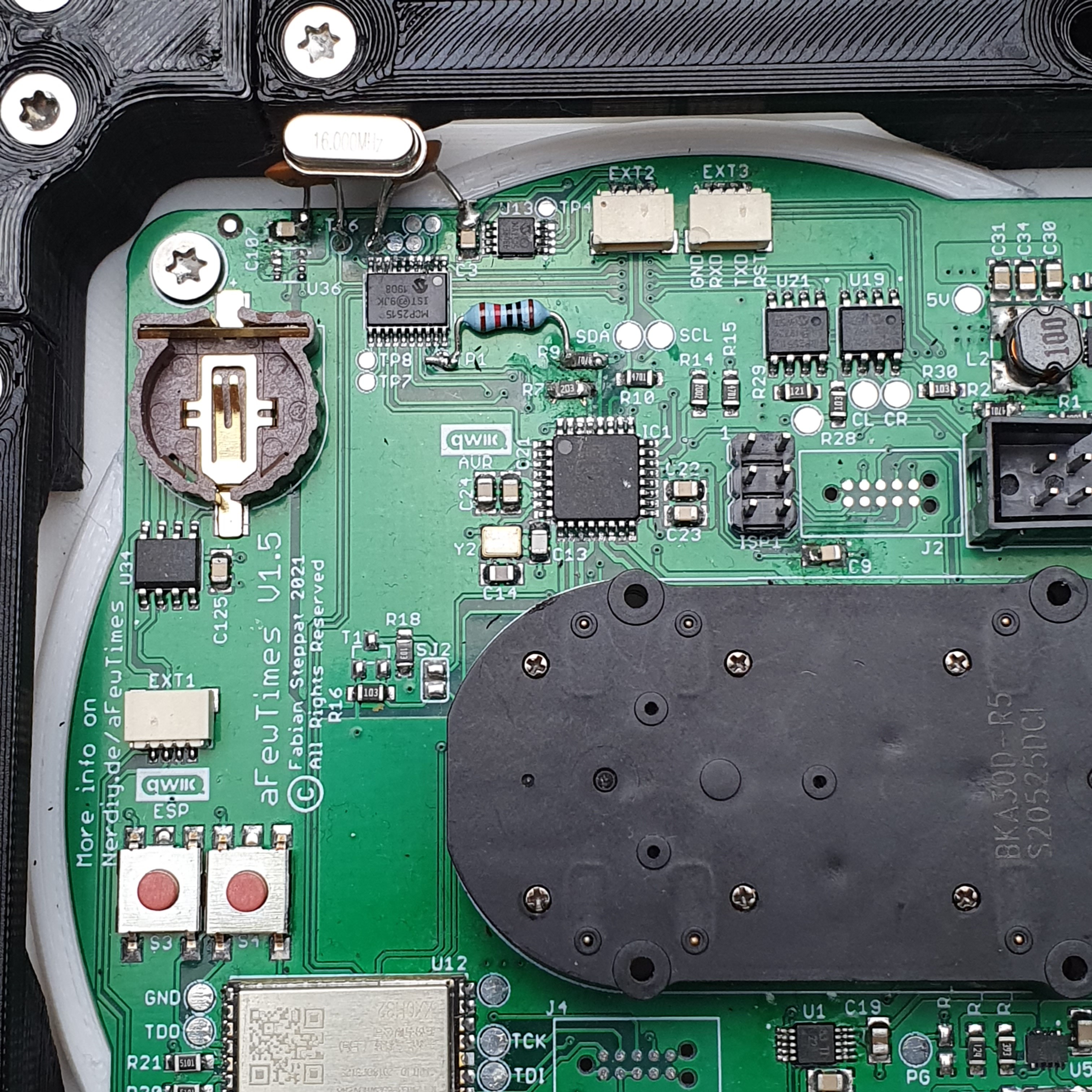
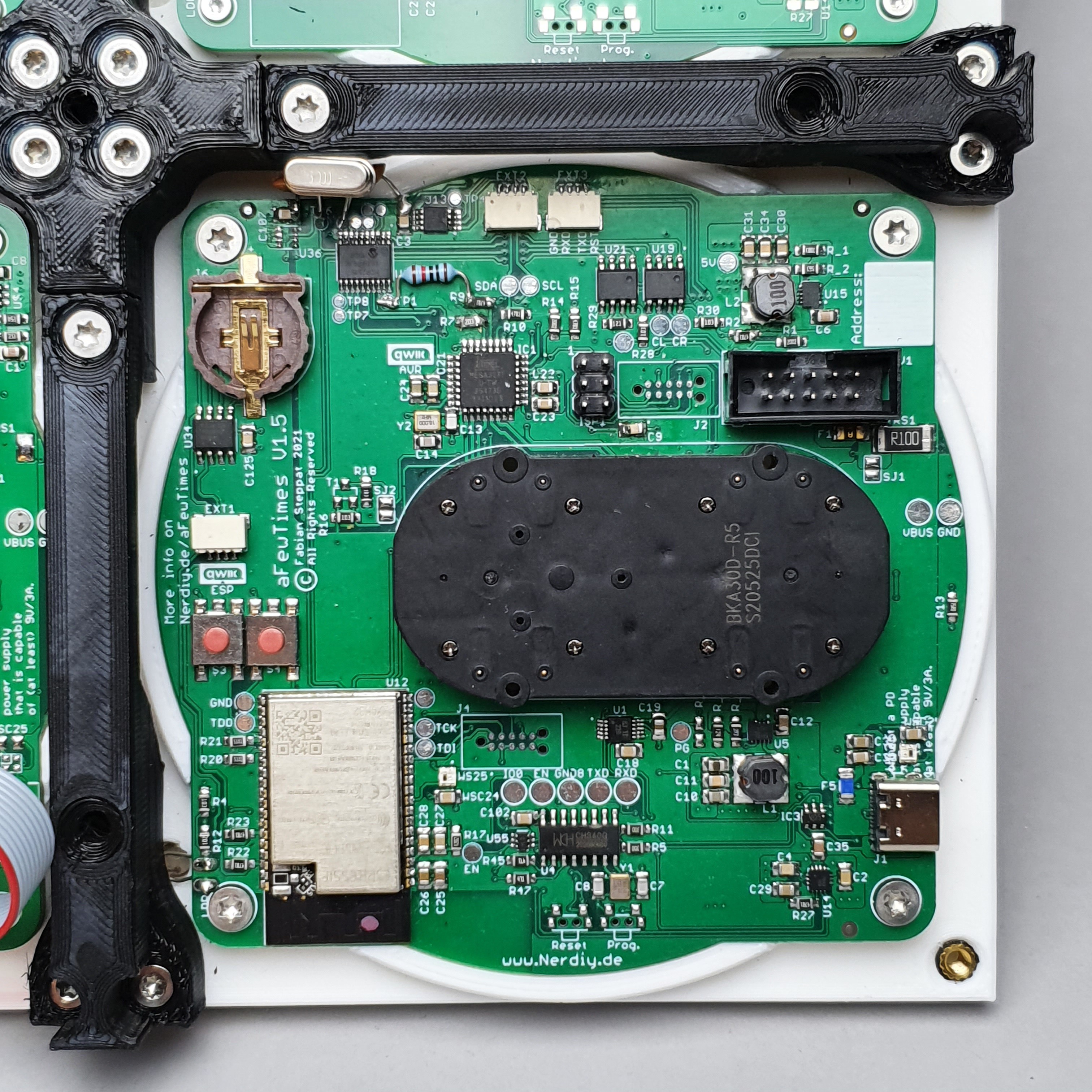
PCB Version 1.5 - Project restart
08/05/2024 at 21:10 • 0 commentsThe PCB Version 1.5 is a big step from the initial approach. Basically I completely redisgned the inital apprach. When I first started with this (and realized it does not work as expected) I was a bit frustrated and the whole project was buried for some years.
In the meantime I gained some experience in PCB and CAD design which contributed a bit to this new design.
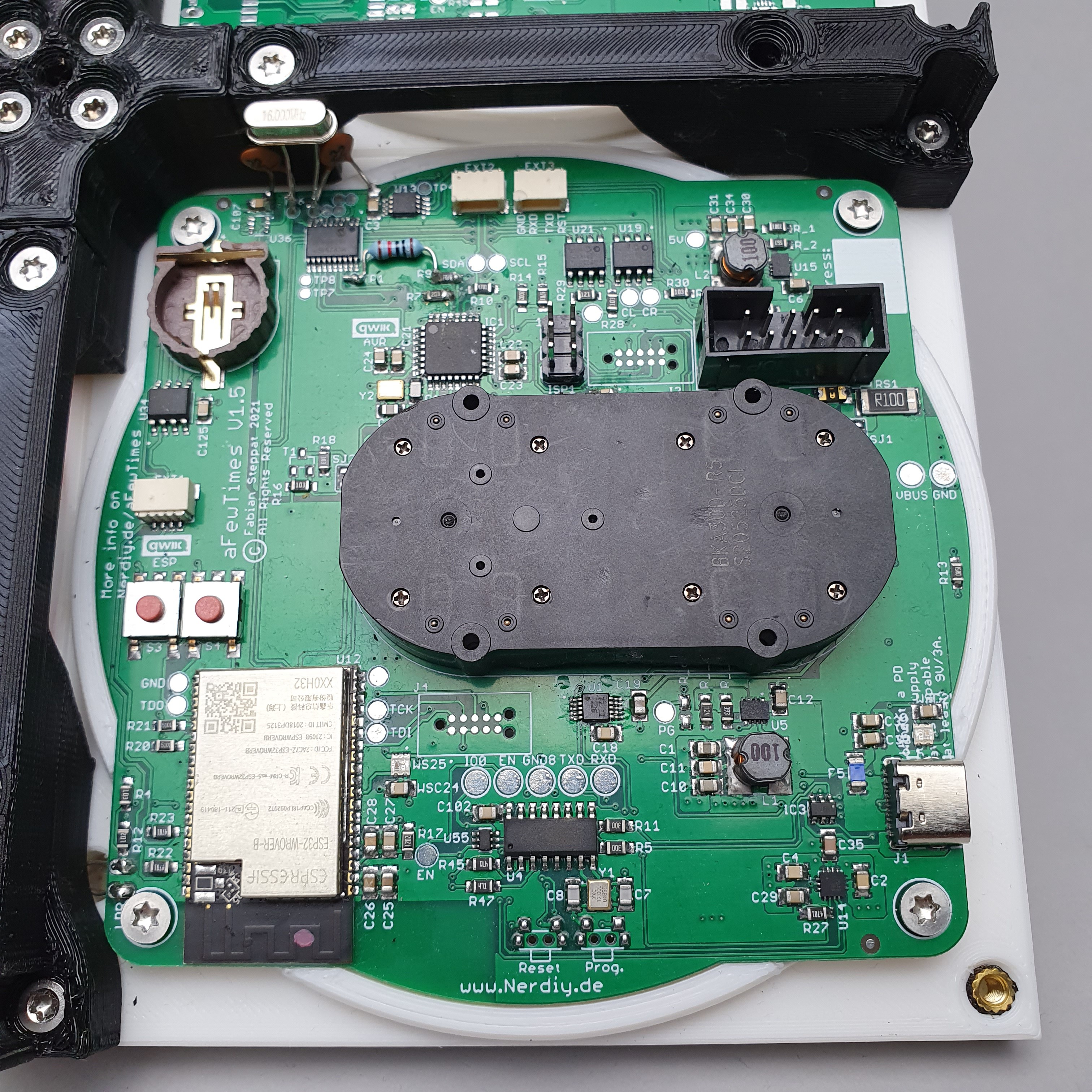
The new design is now based on a BKA30D dual stepper (like many other of these projects).
Each PCB has space for the slave module and master module electronics.
The slave module shall only control the stepper motors and some other parts that need to be available on every module.
The master module has additionally an ESP32 installed that controls all other slave modules via CAN bus based communication.
![]()
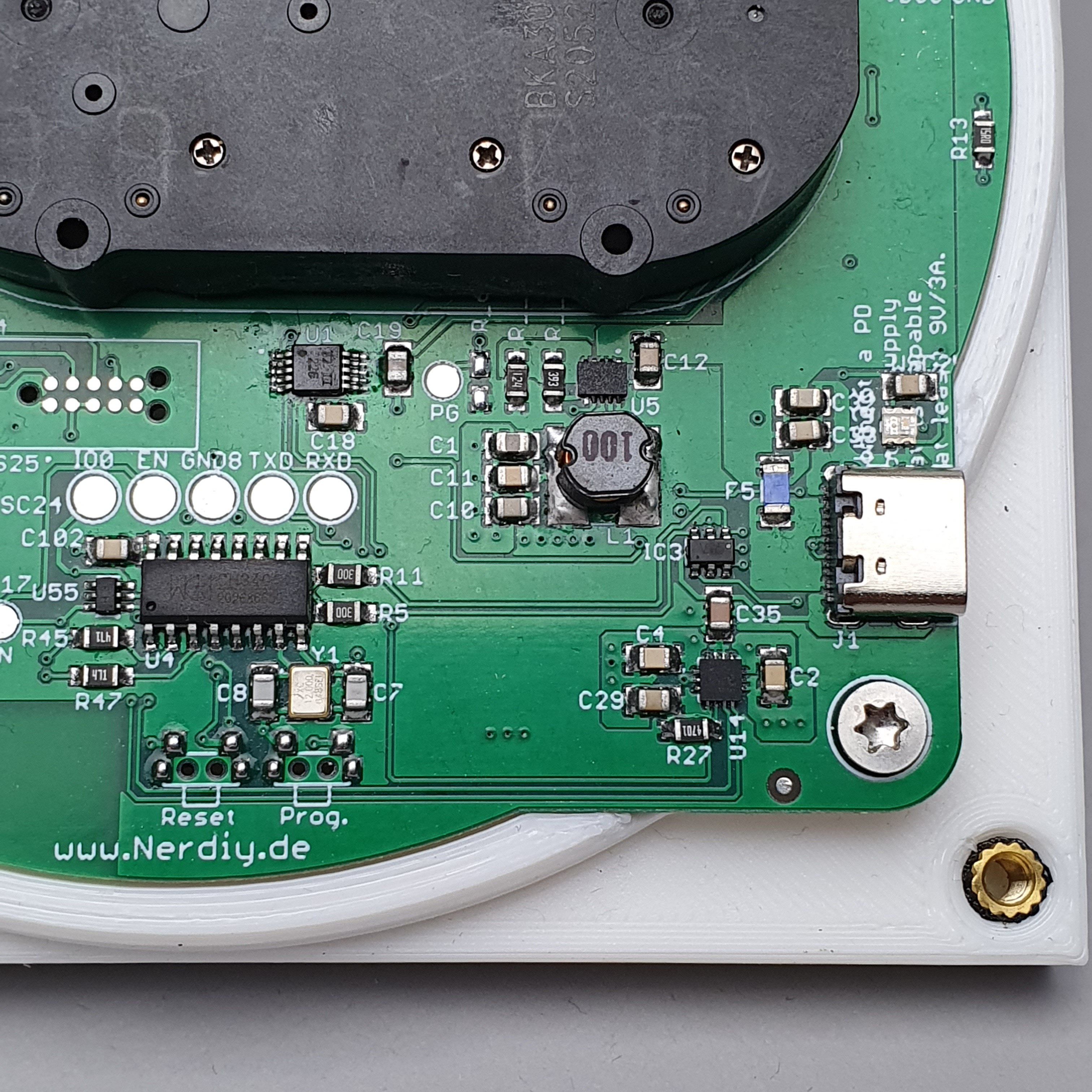
First time in one of my projects that I use a FUSB302 based Power Delivery phy. ![]()
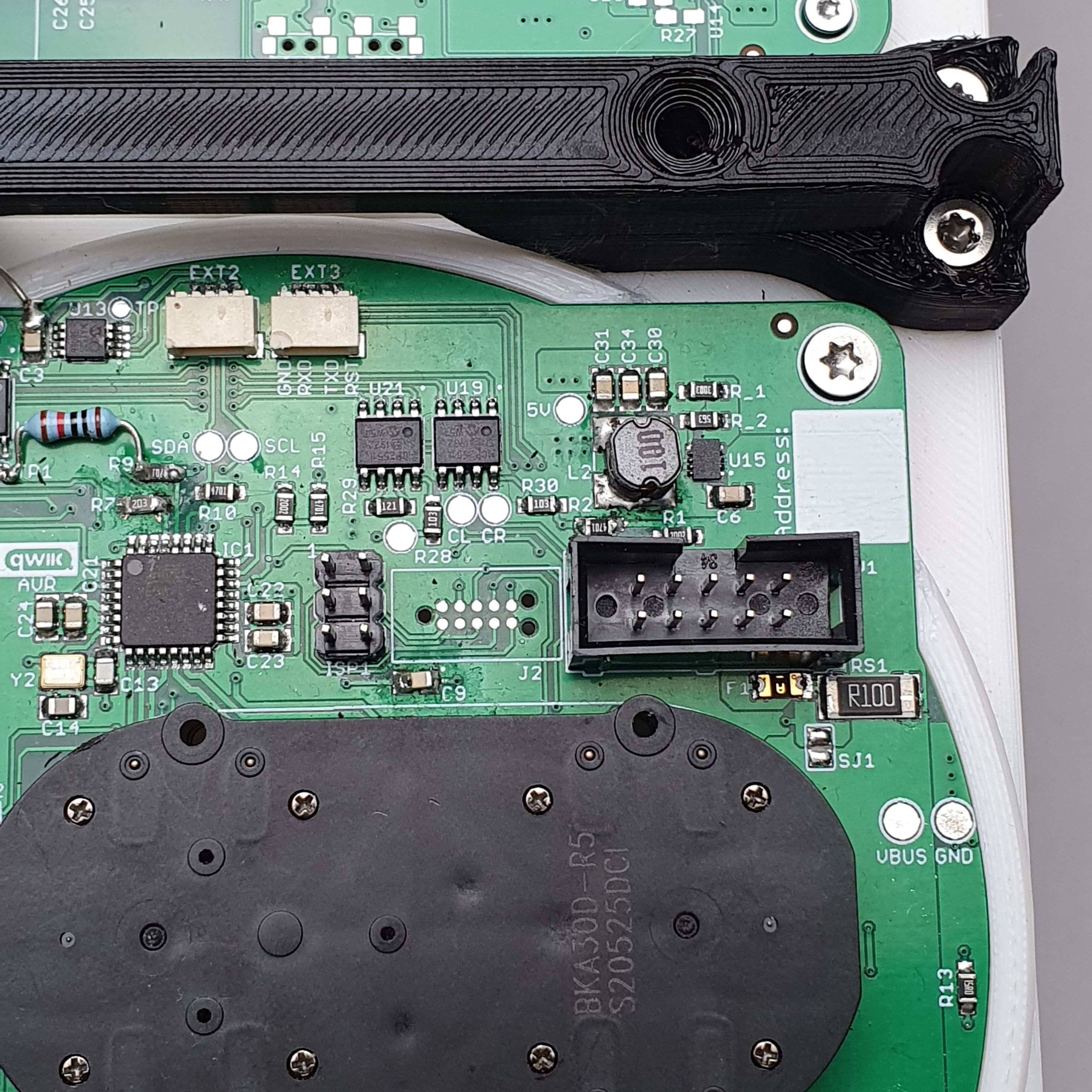
All modules can be connected to each other via a 10 Pin connector and flat ribbon cable. ![]()
Of course I had some "whoopsies" on my first PCB version. I corrected them with the good old wired components. :) ![]()
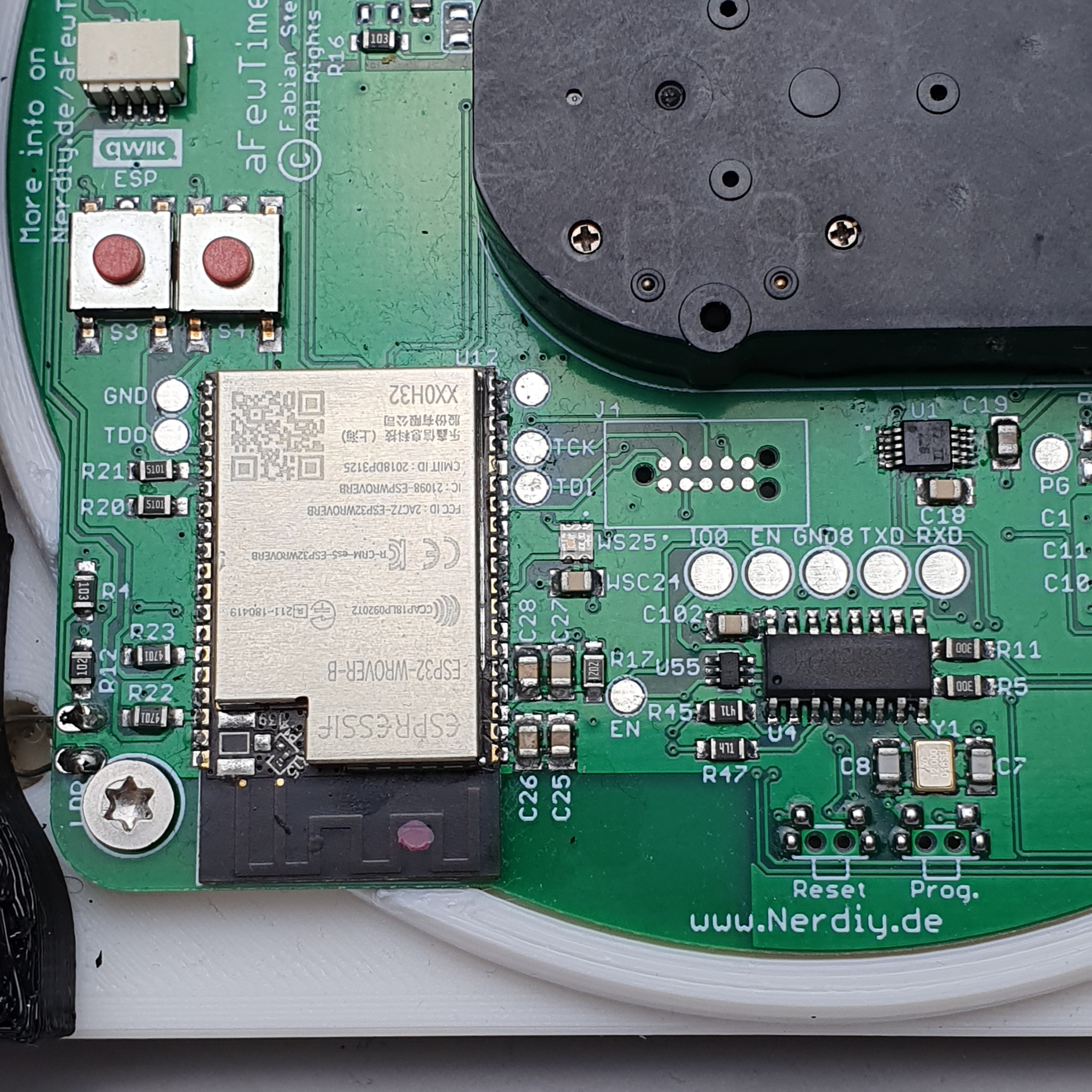
Overview of the completely assembled master module. -
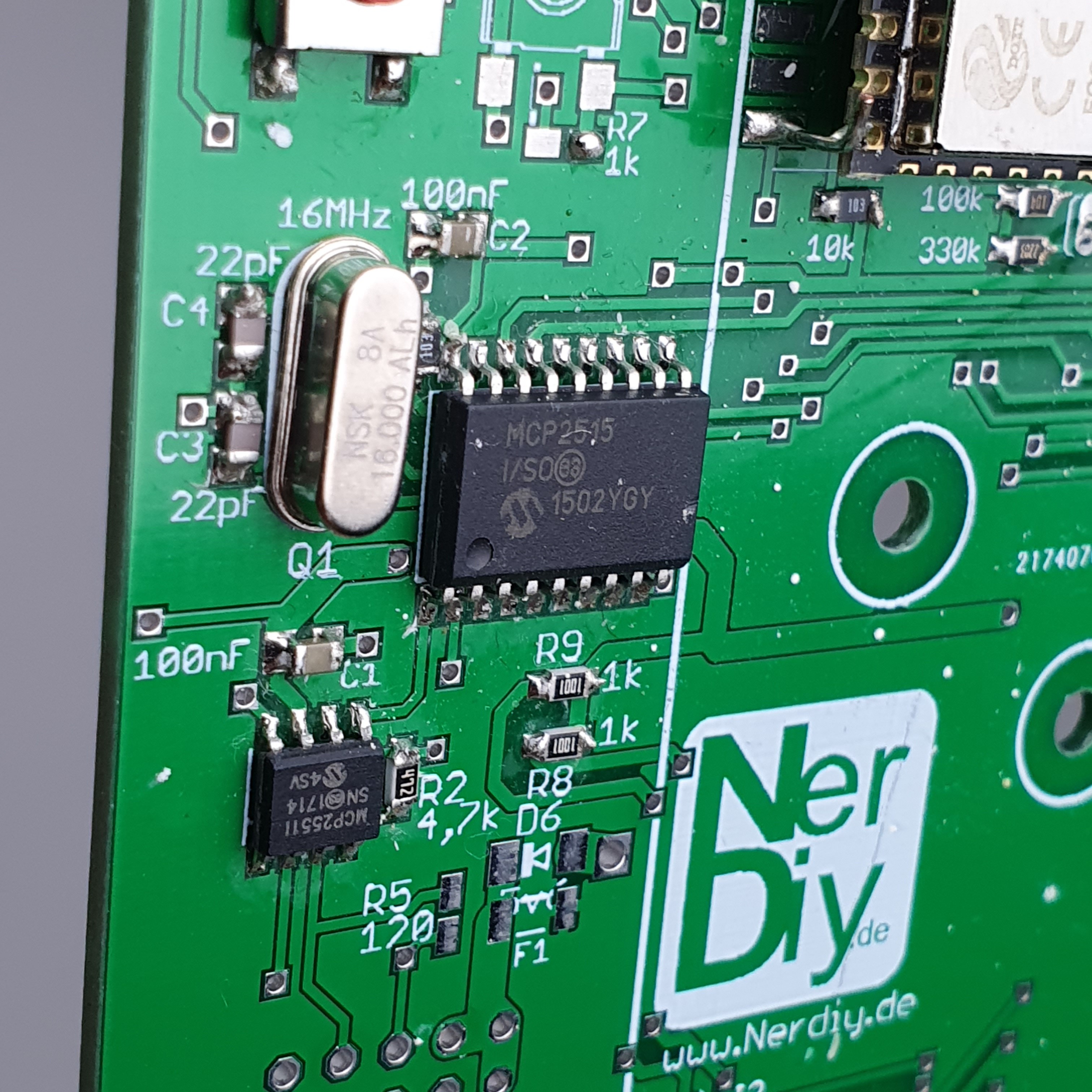
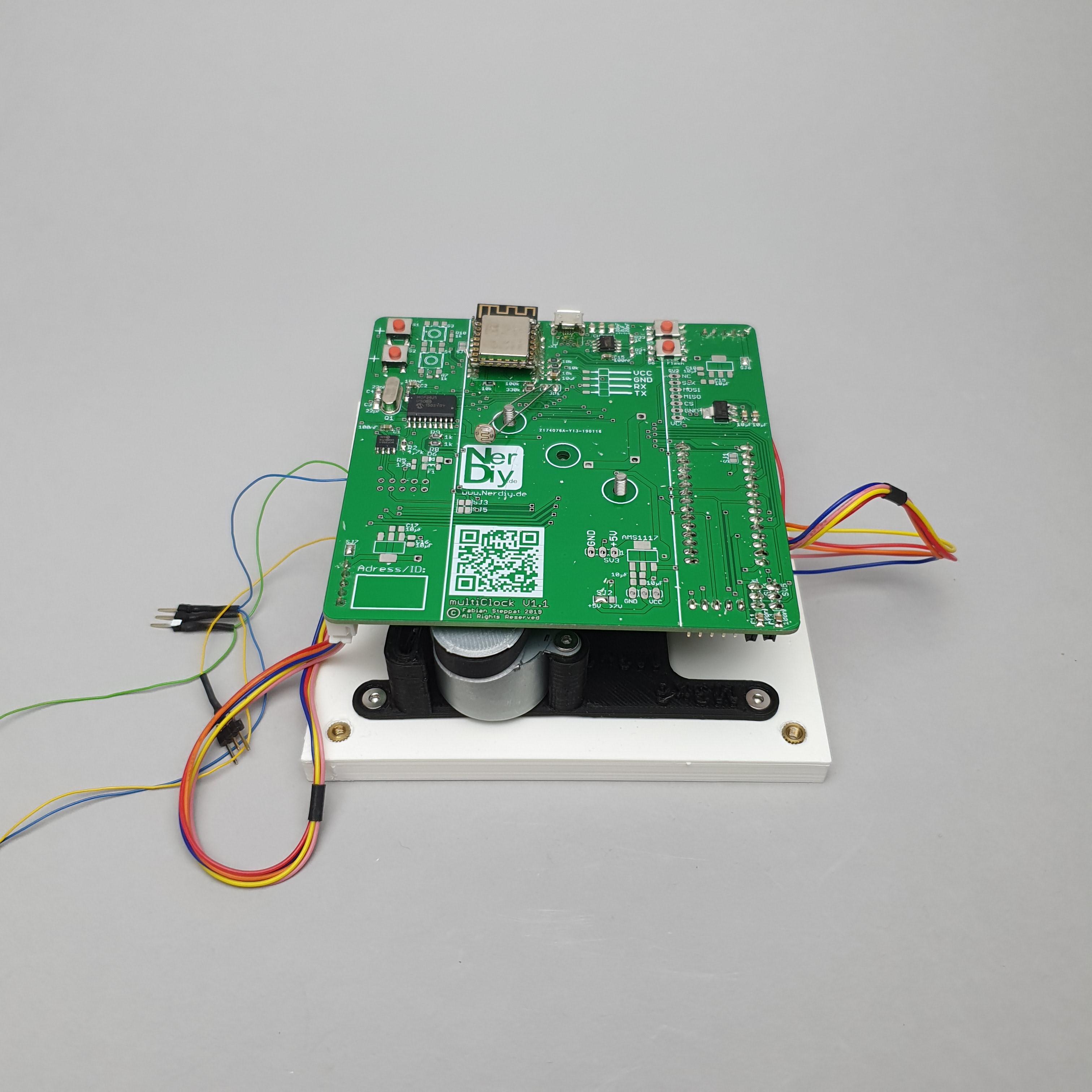
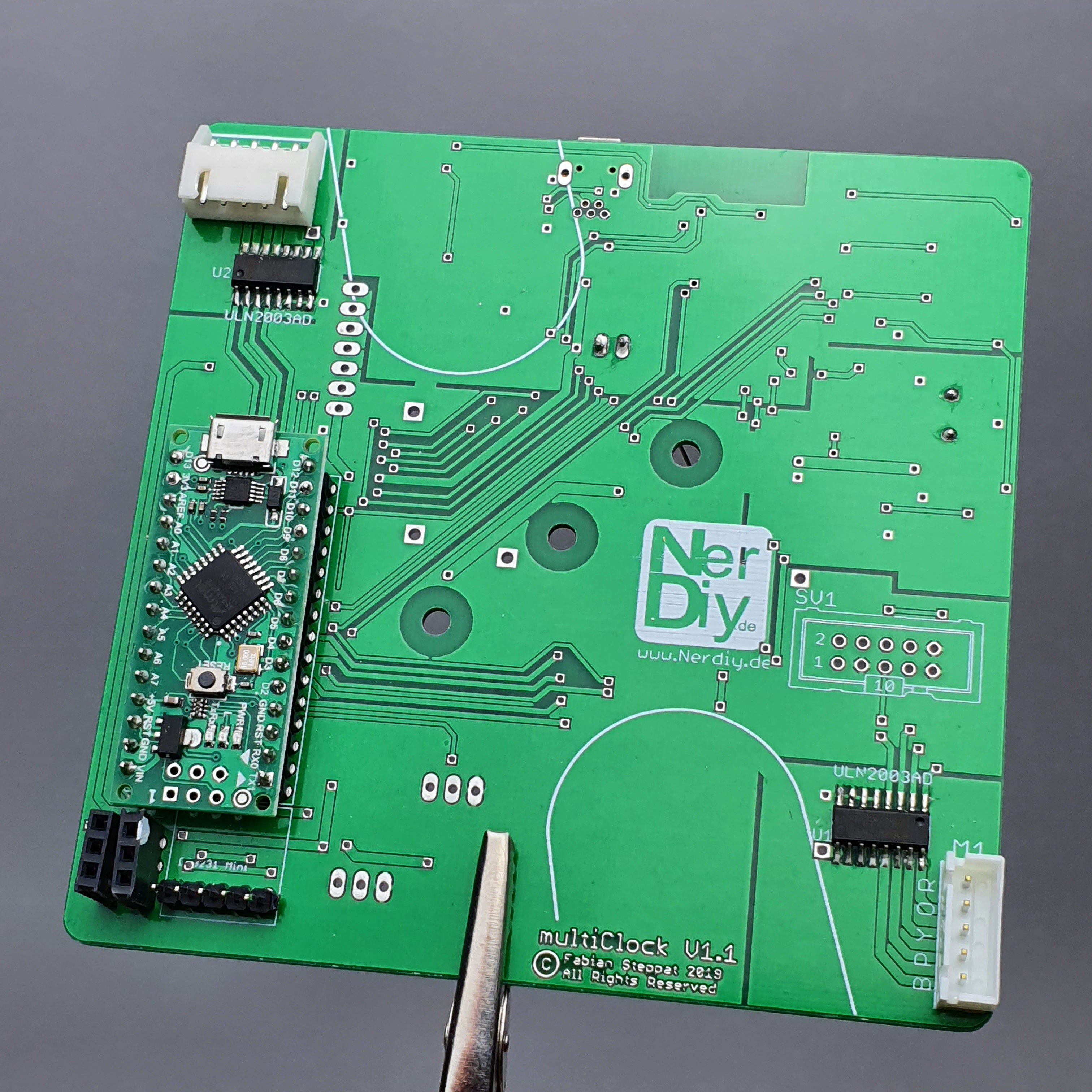
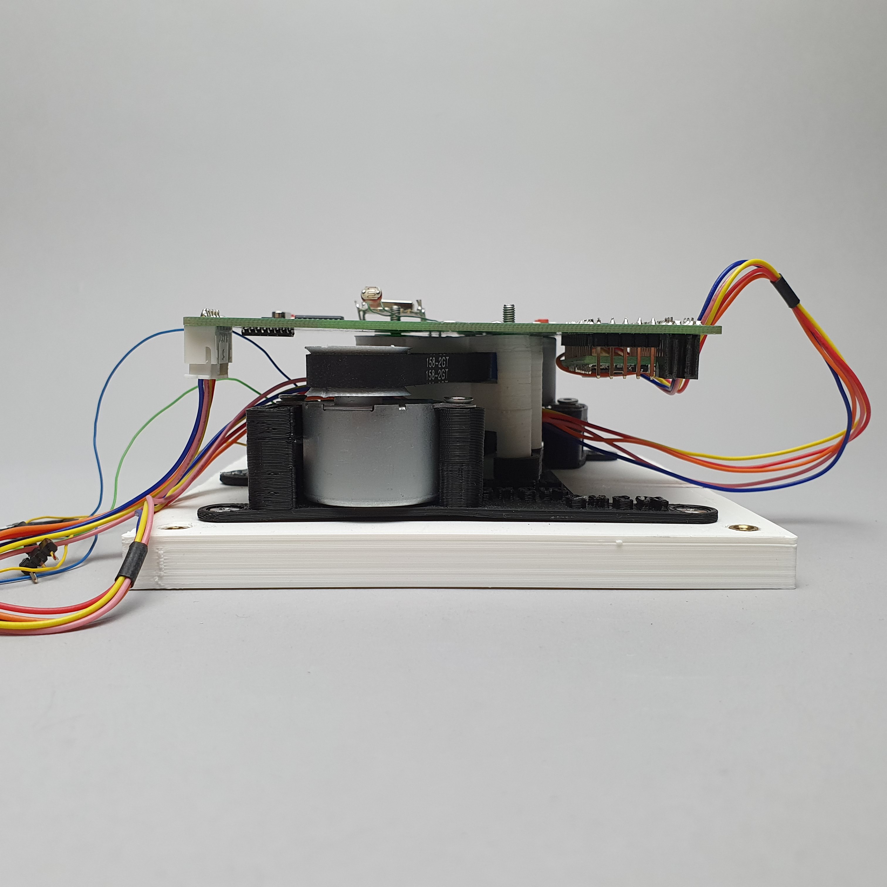
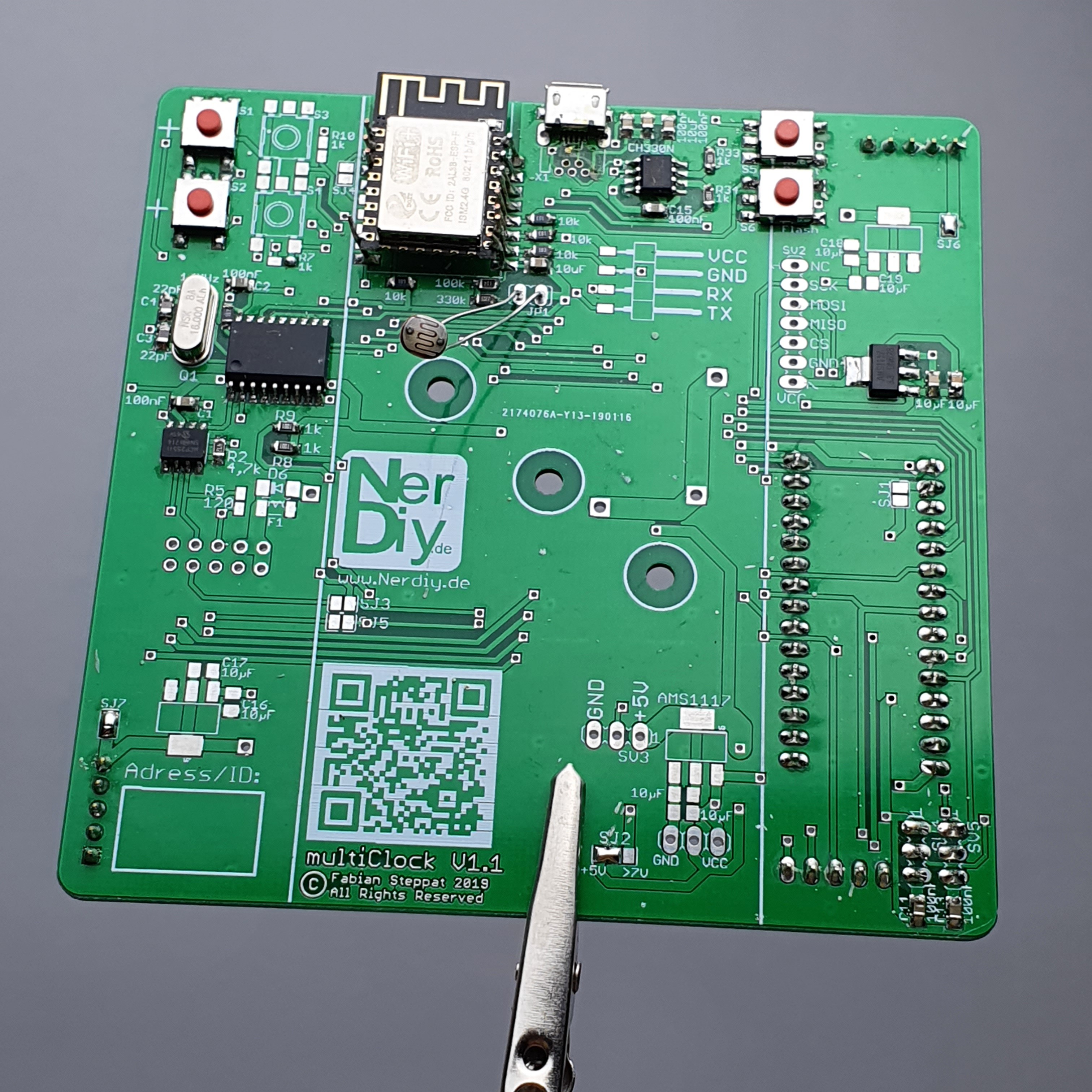
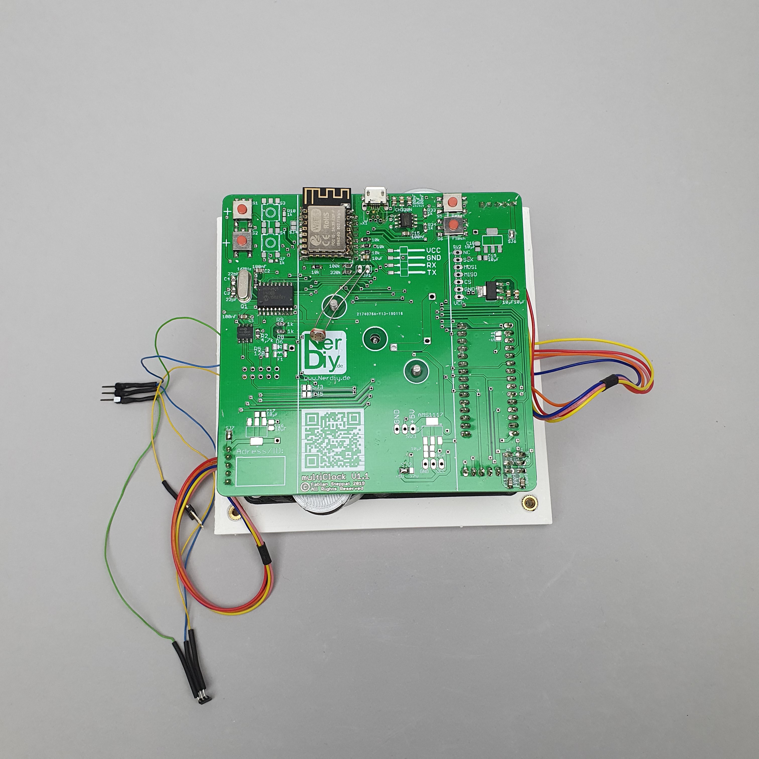
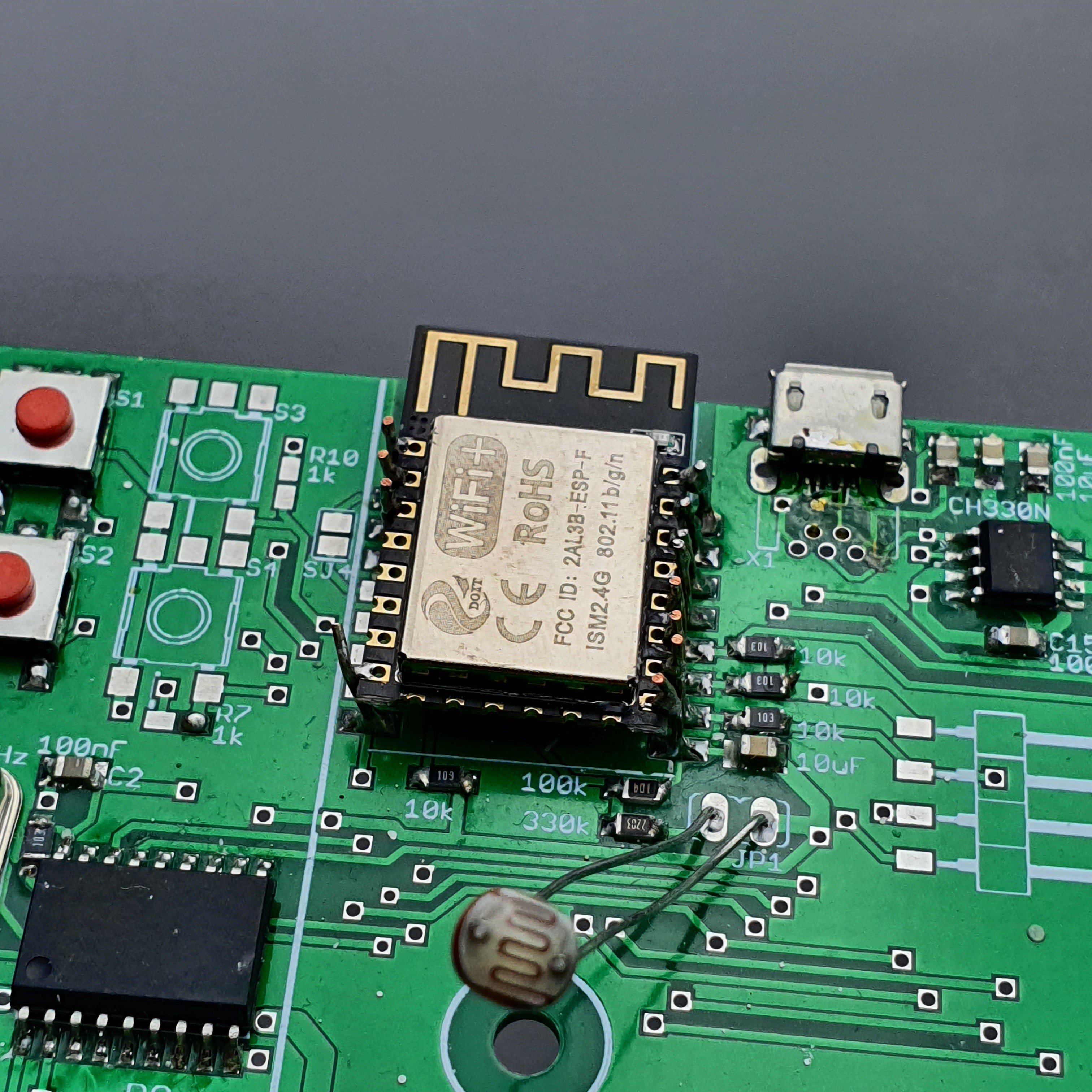
PCB Version 1.1 - The beginning
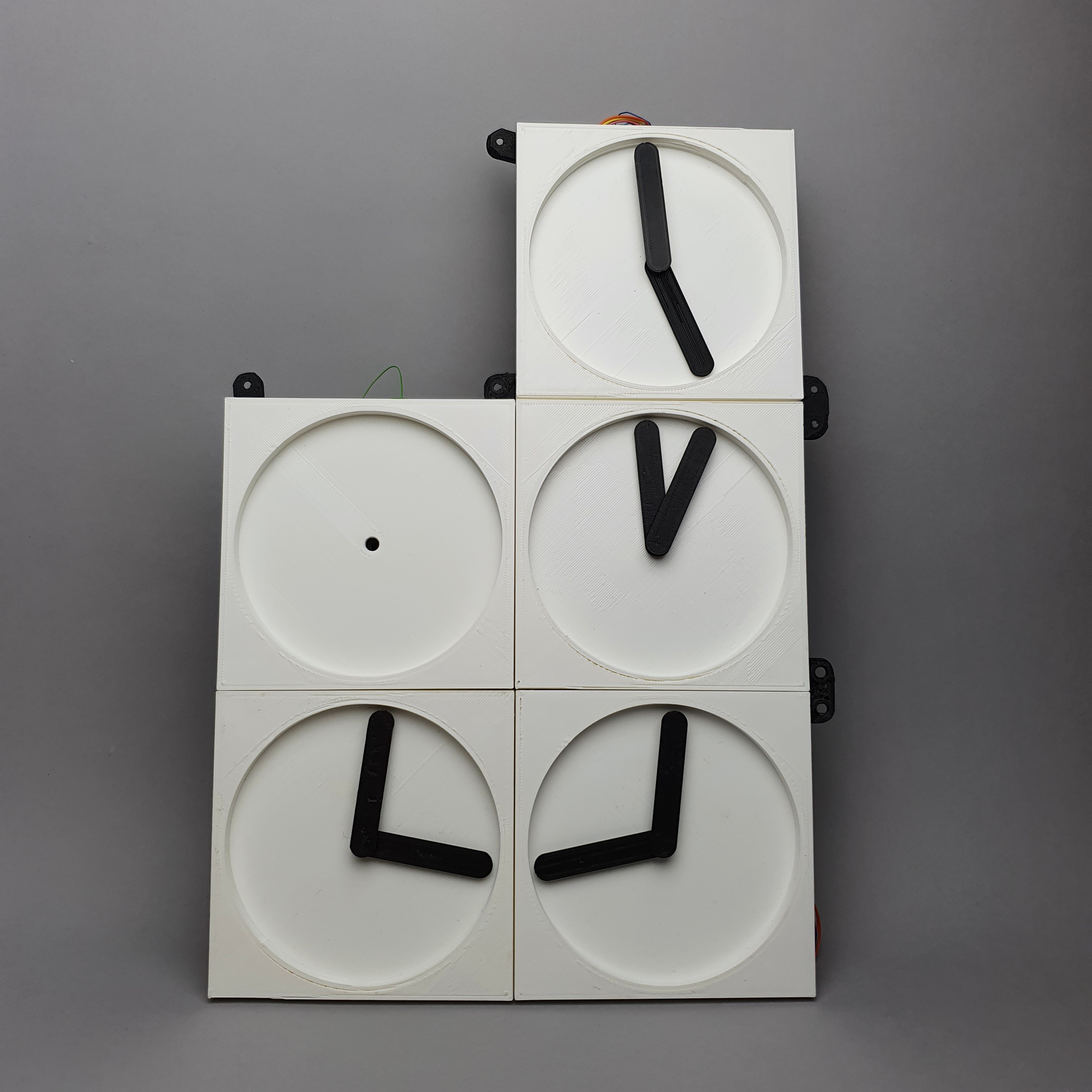
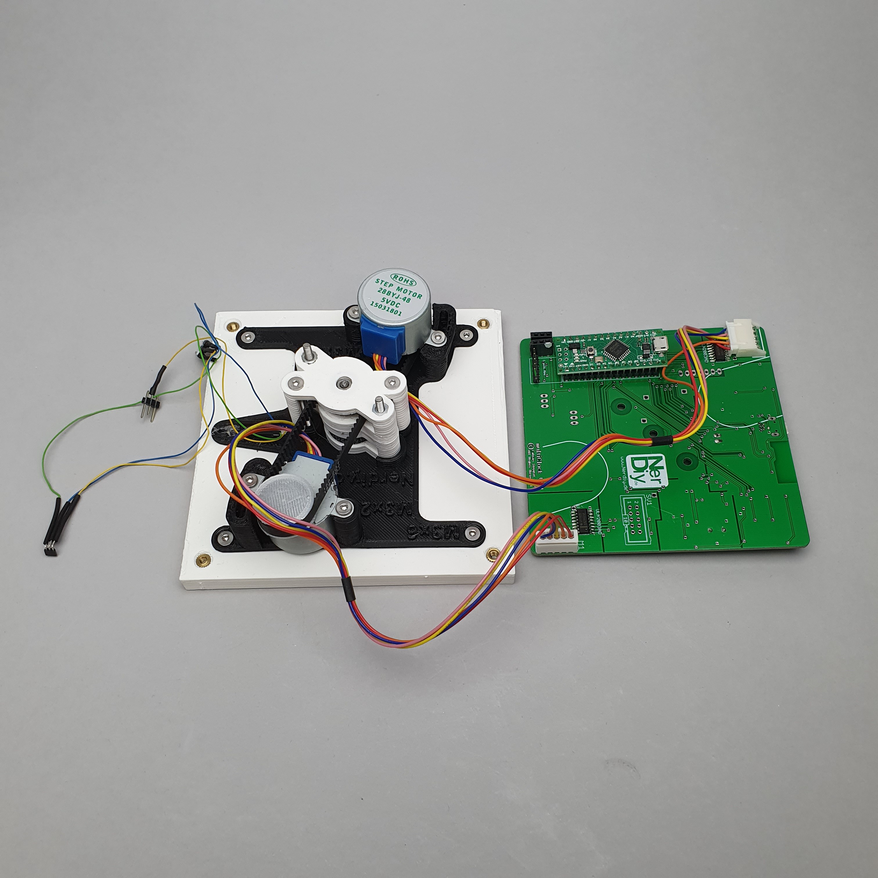
08/05/2024 at 21:09 • 0 commentsThe following pictures show my first design. I started with this a long time ago and even if it ended with a frustrated me, I learned a lot from it.
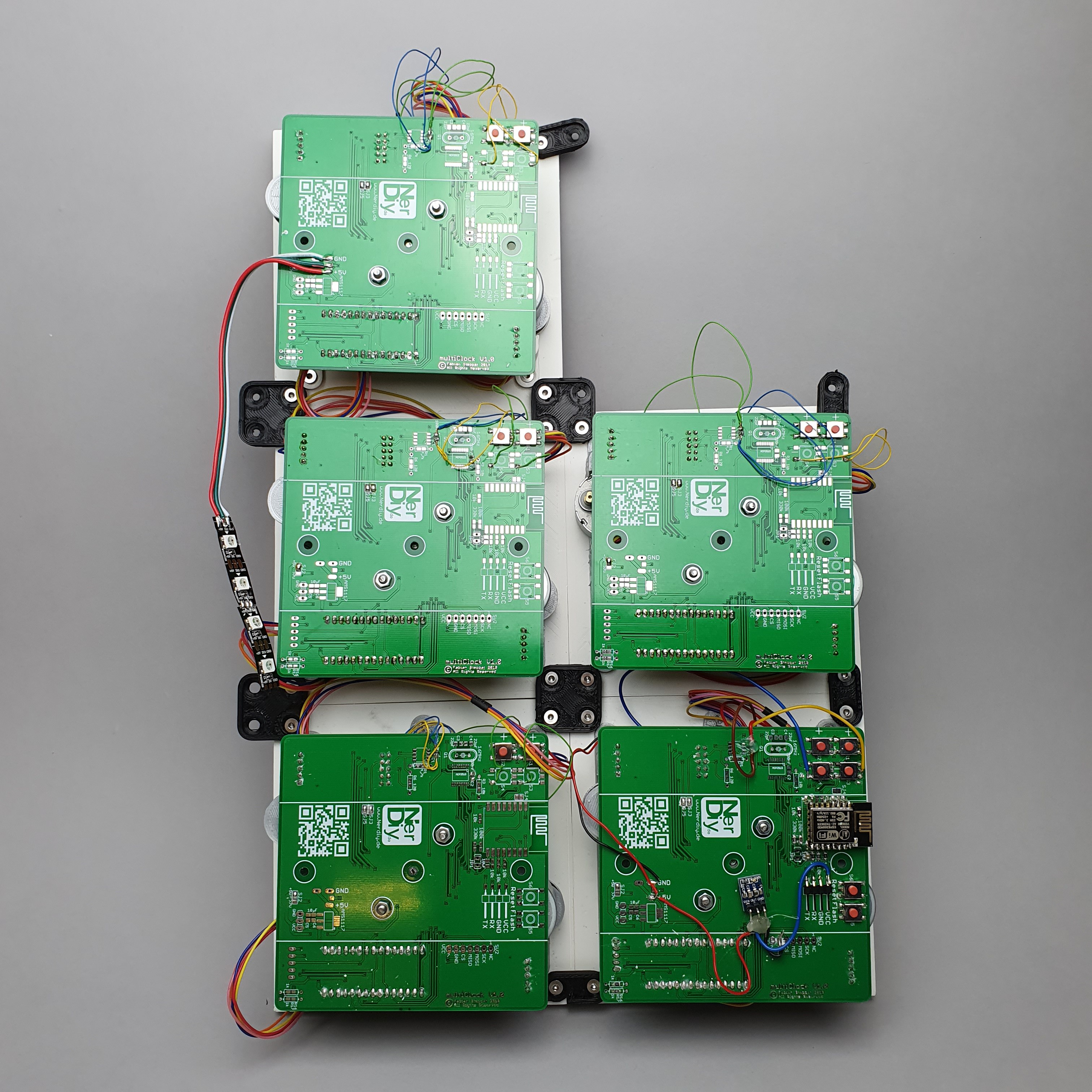
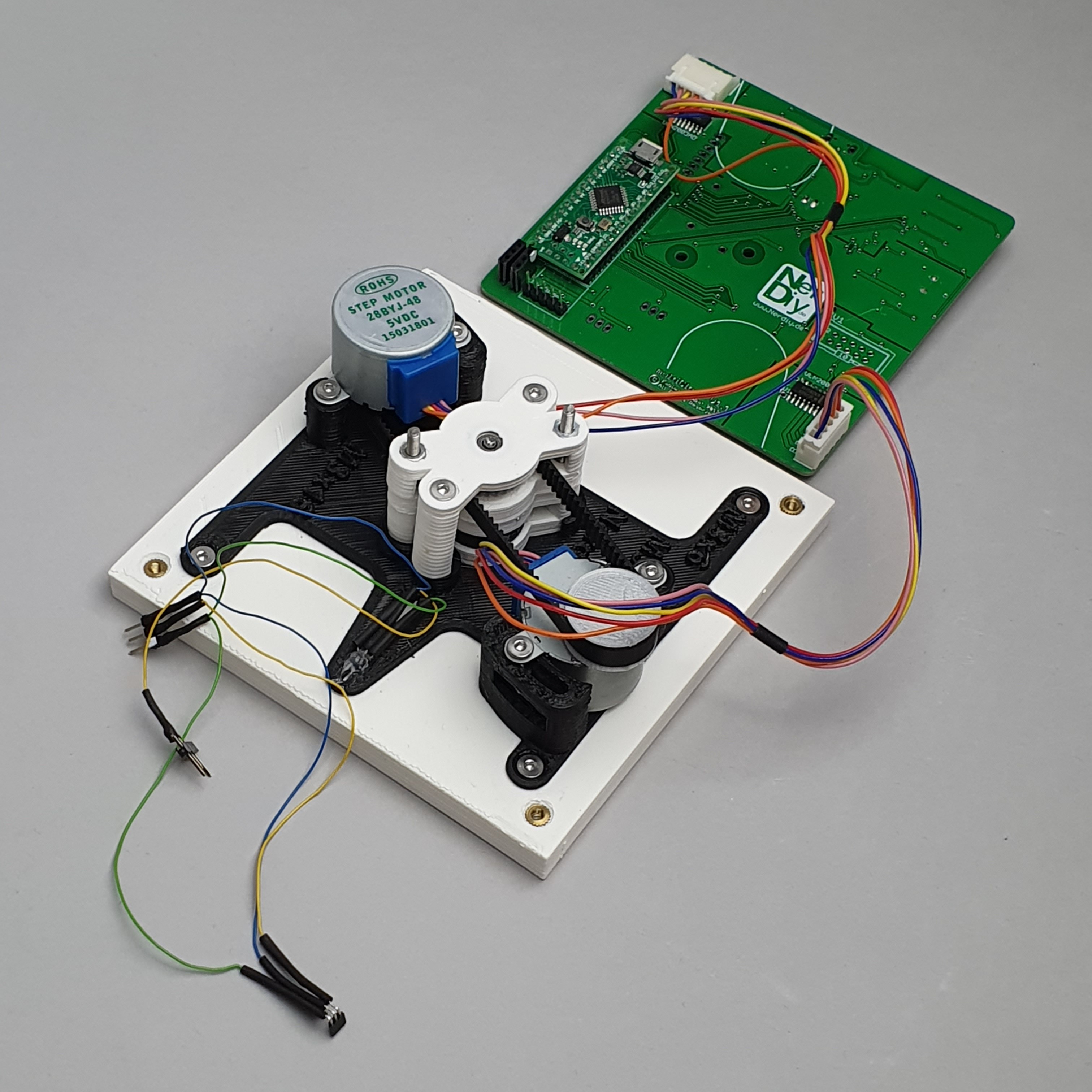
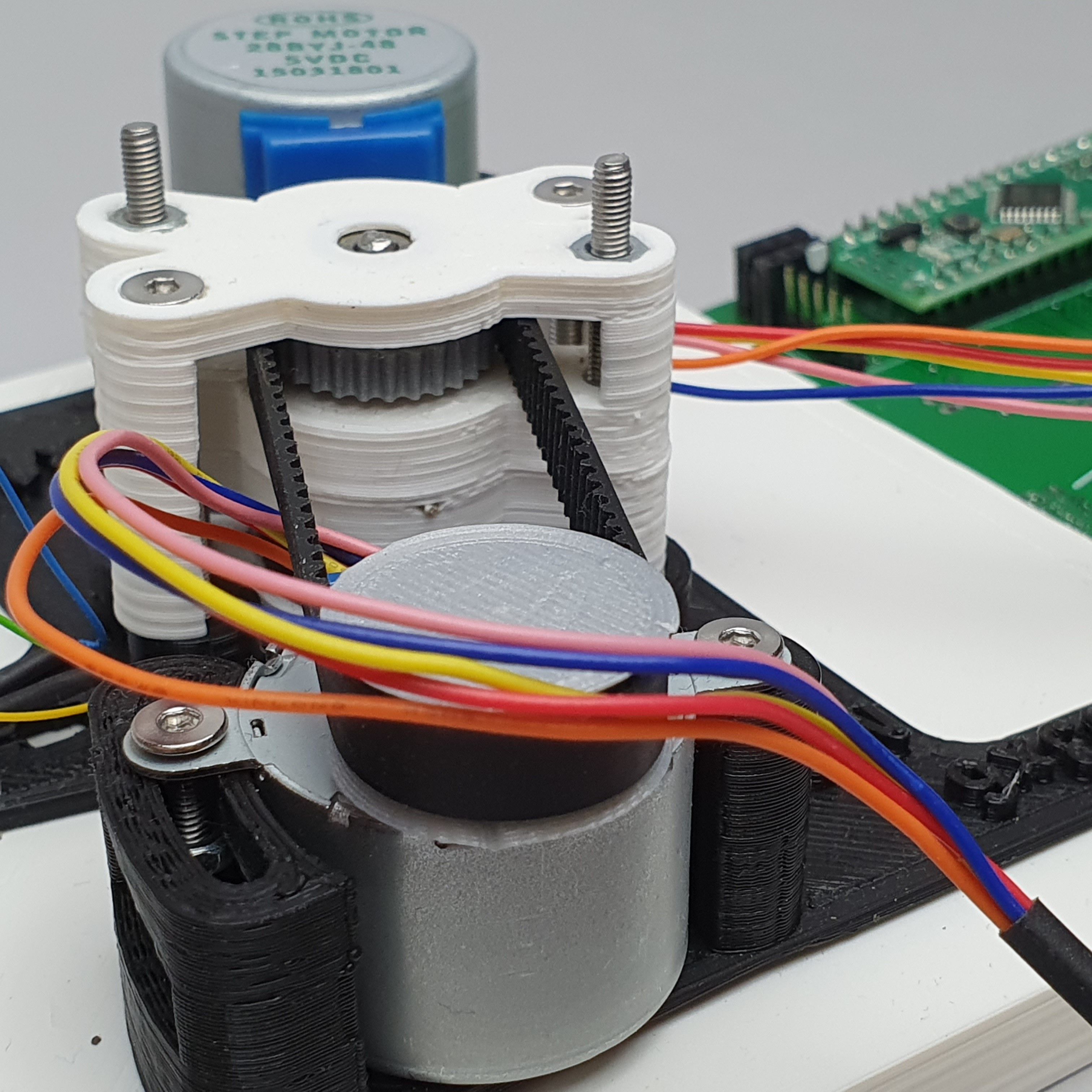
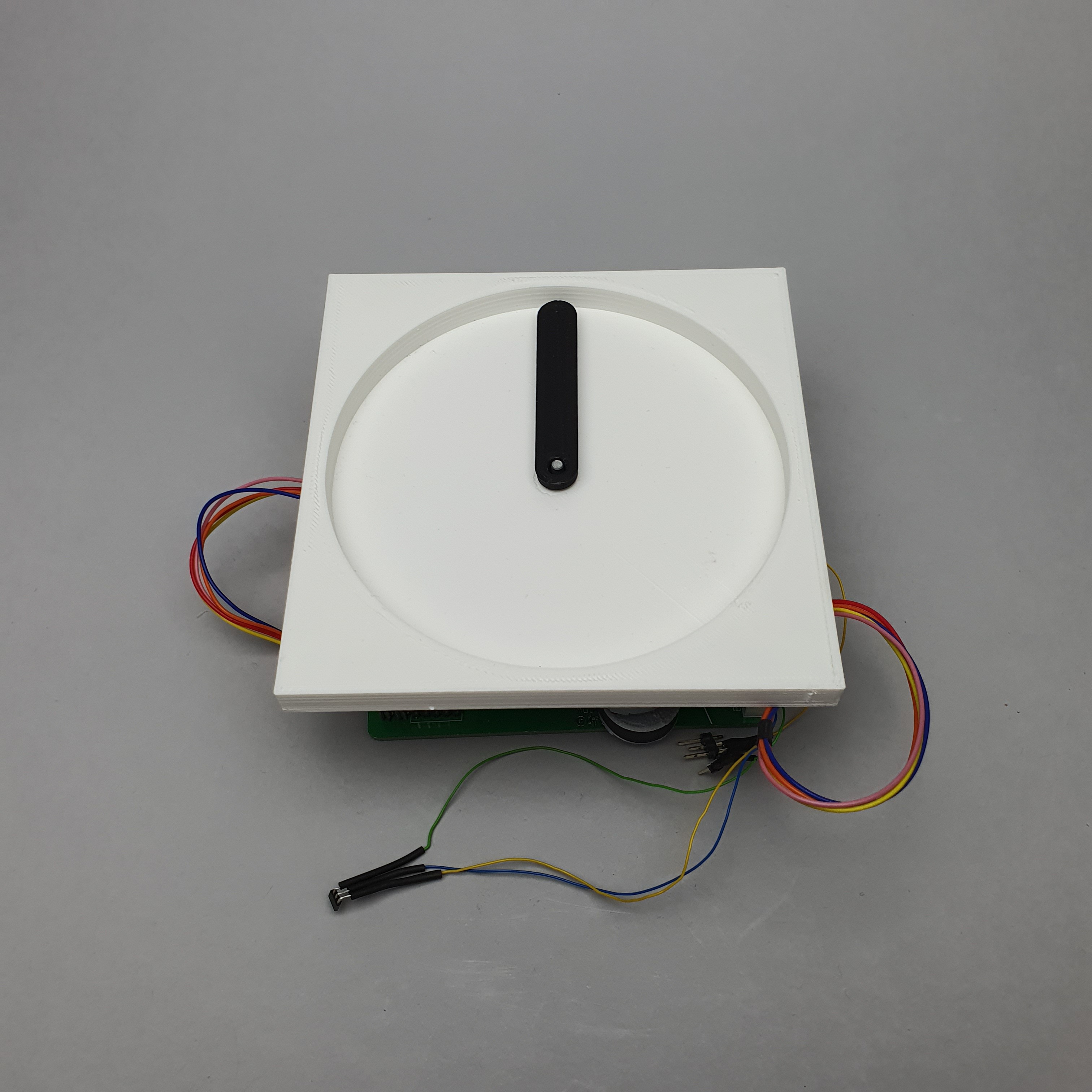
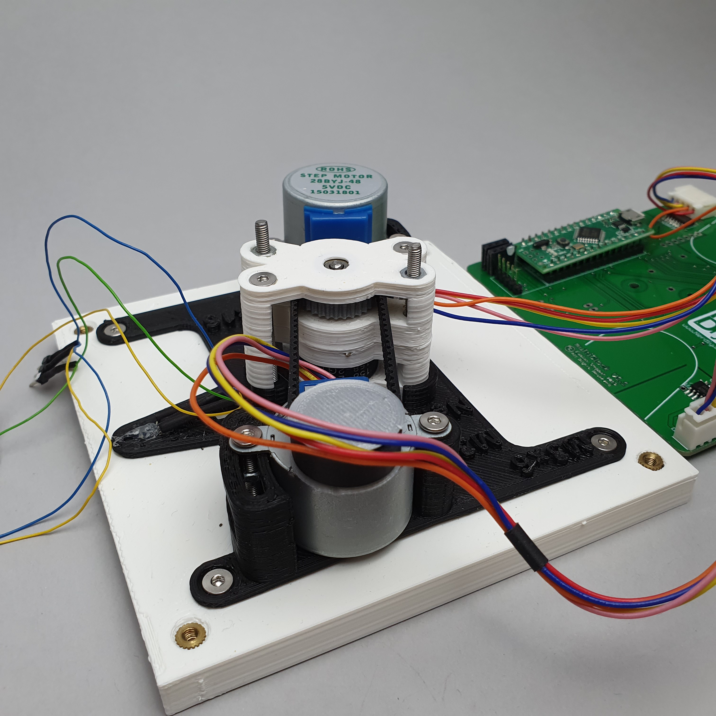
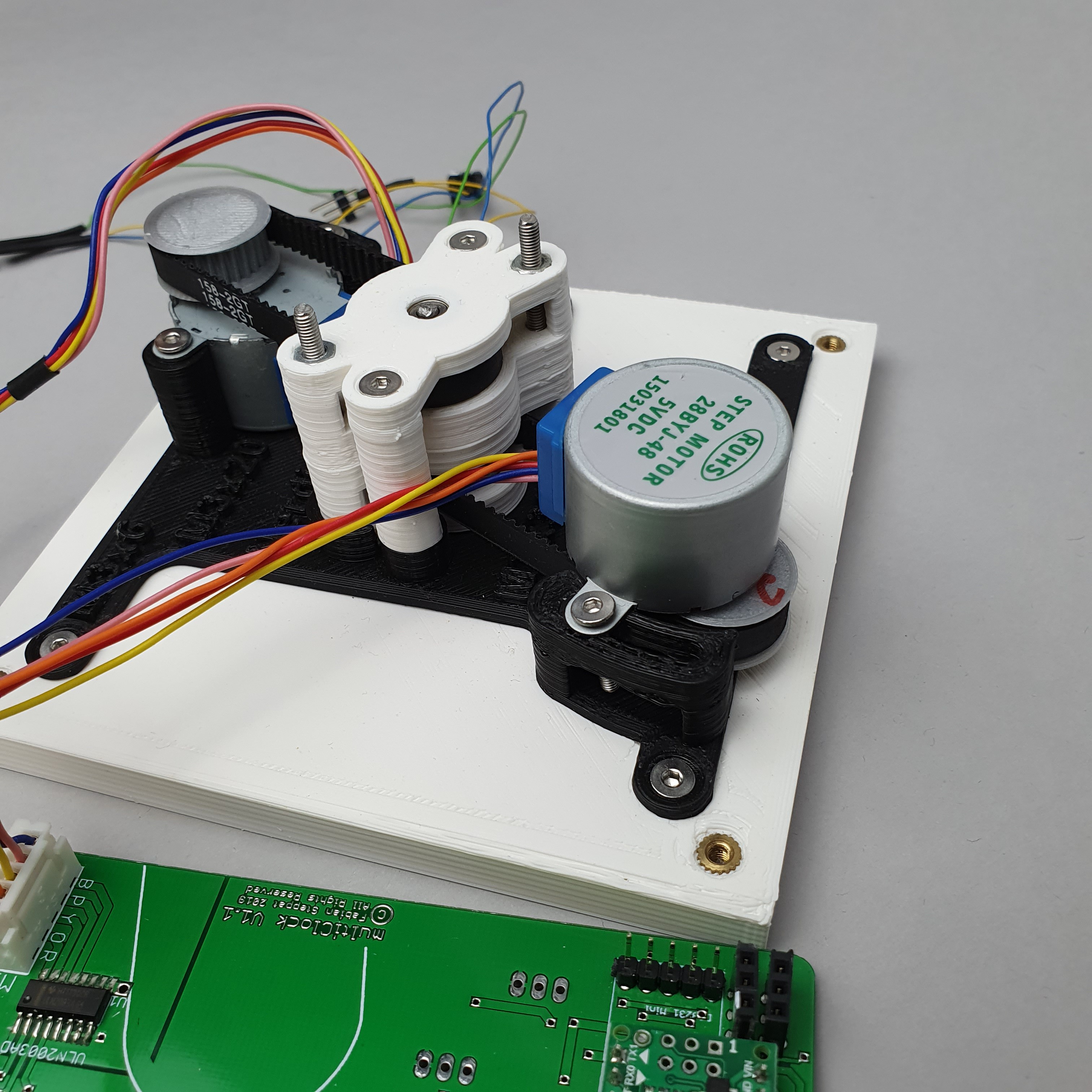
The initial idea was to use the famous 28BYJ-48 stepper motor that controls a belt driven 3D printed axle mechanism.
Long story short: In theory it worked, but in daily life the pointers often lost their calibration and therefore lost the alignment.
After investing so much time and money I was really frustrated at that point and buried the whole project for some time.
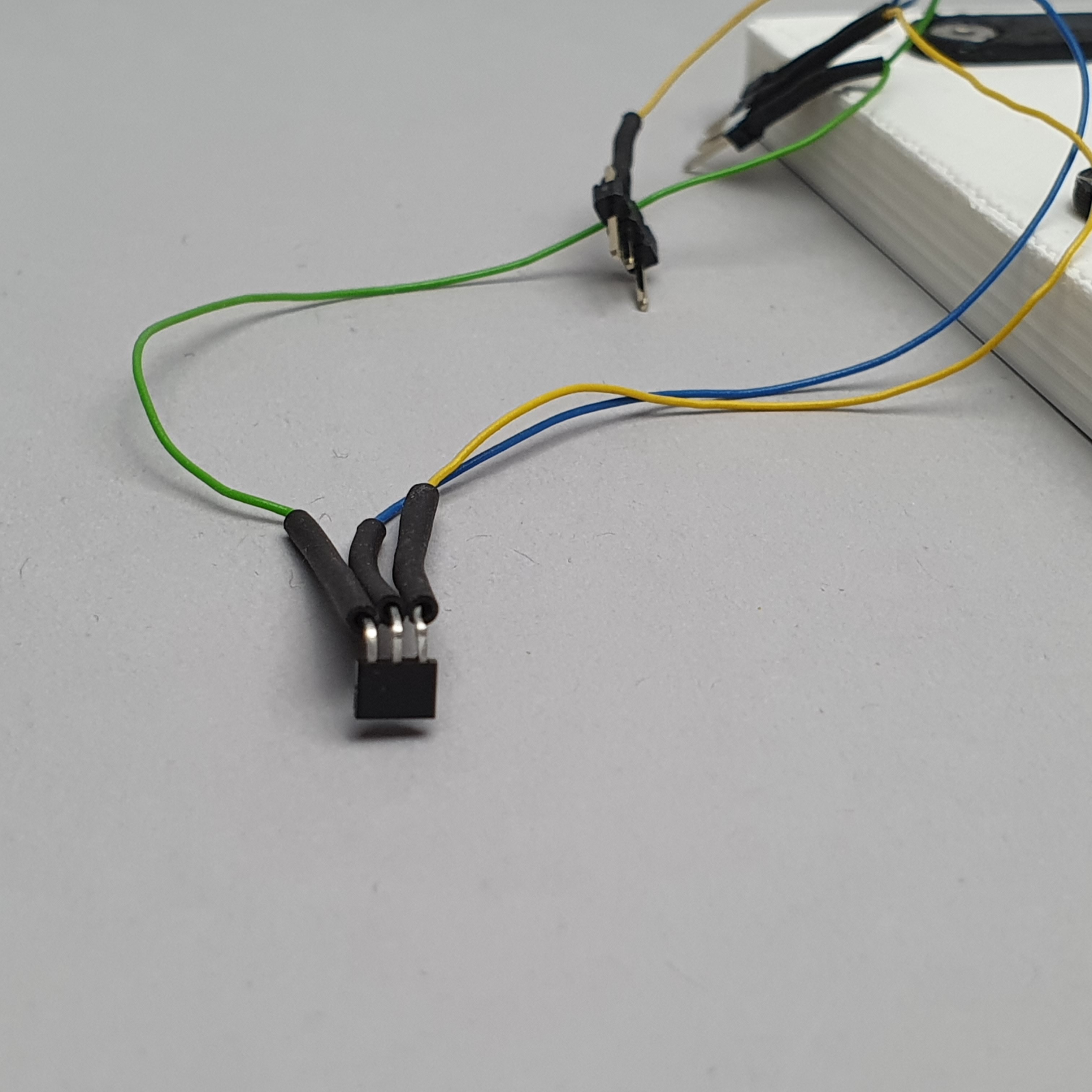
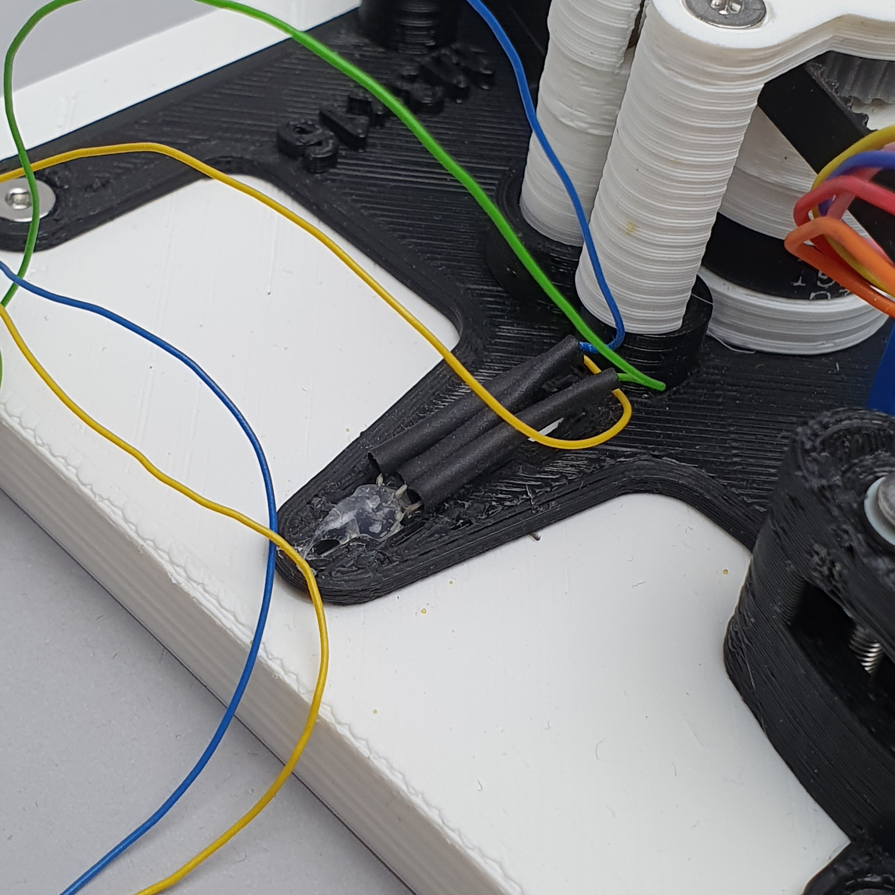
Below you can see some pictures of the initial prototype.
![]()
![]()
![]()
![]()
![]()
![]()
![]()
![]()
![]()
![]()
![]()
![]()
![]()
![]()
![]()
![]()
![]()
 Fabian