 kutluhan_aktar
-
1Demonstration Videos
Since this HVAC malfunction detection device performs various interconnected features between different development boards and the web application (dashboard), I needed to compartmentalize consecutive processes and describe functions under the same code file separately to provide comprehensive step-by-step instructions.
Thus, I highly recommend watching the demonstration videos before scrutinizing the tutorial steps to effortlessly grasp device capabilities that might look complicated in the instructions.
-
2Step 0: A brief introduction to device features and structure
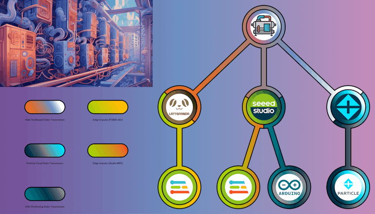
As my projects became more intricate due to complex designs and multiple development board integrations, I decided to create concise illustrations to improve my tutorials, visualize the special tasks associated with each development board, and delineate the complicated data transfer procedures between different boards or complementary applications.
Thus, before proceeding with the following steps, I highly recommend inspecting these illustrations to comprehend the device features and structure better.
Note: Since downsizing these high-resolution illustrations is necessary for loading the tutorial page, I noticed the text on the illustrations lost legibility. Therefore, I also added the original image files below for further inspection.
![]()
![]()
![]()
![]()
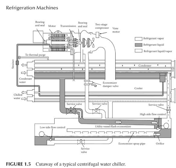
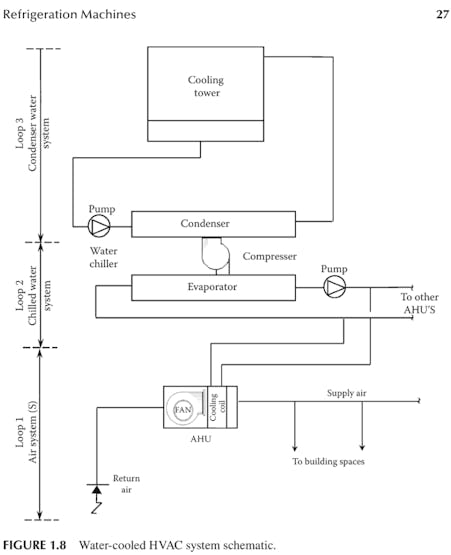
Before designing my simplified water-based HVAC system to simulate the required component failures for data collection and in-field model testing, I thoroughly inspected common water-cooled HVAC mechanisms[4] to understand the inner workings of applying water as a coolant for transferring excess heat in industrial processes.
![]()
![]()
-
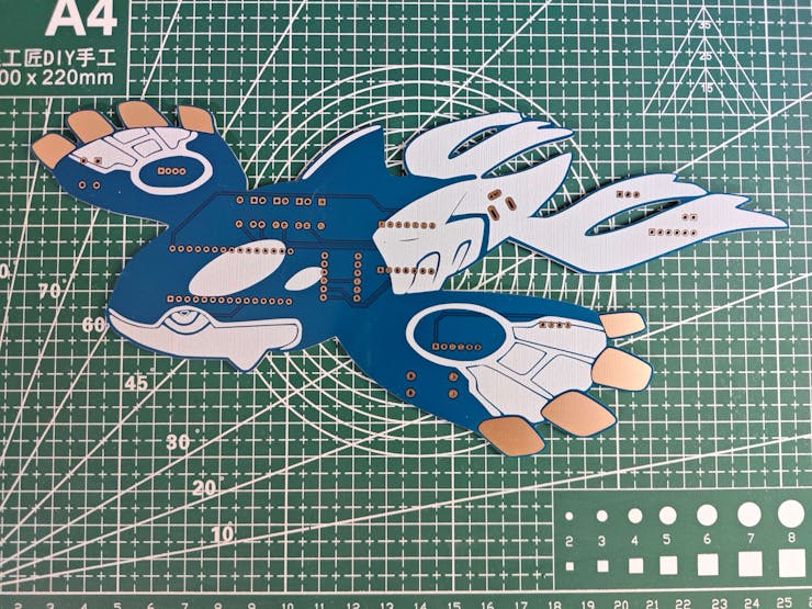
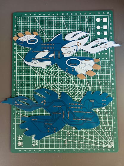
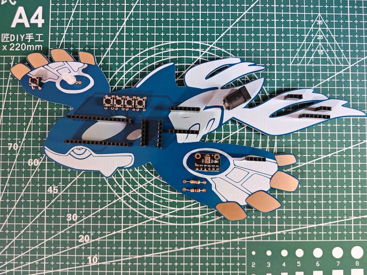
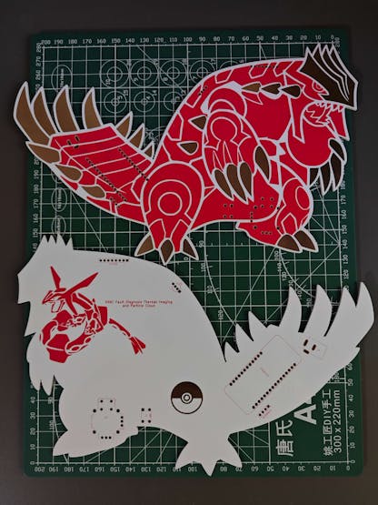
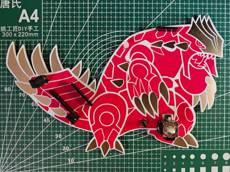
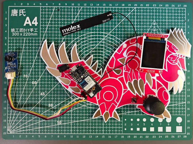
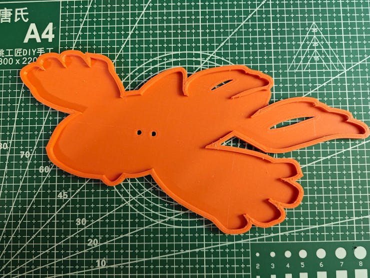
3Step 1.a: Designing and soldering the Kyogre-inspired PCB
As I was developing device features, I noticed that I needed to run different data collection procedures and machine learning models simultaneously. Therefore, I decided to create two separate PCB designs to run the required tasks conclusively. Since I wanted my PCB designs to represent the equilibrium of cooling fan failures and thermal (heat) malfunctions, I got inspired by two ancient rival Pokémon — Kyogre and Groudon. Their legendary fights depict the epitome of the conflict between water cooling and exuberating heat :)
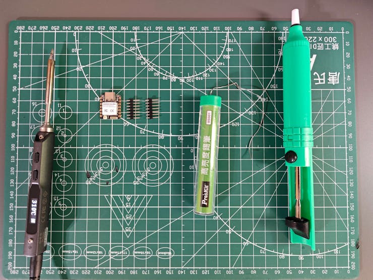
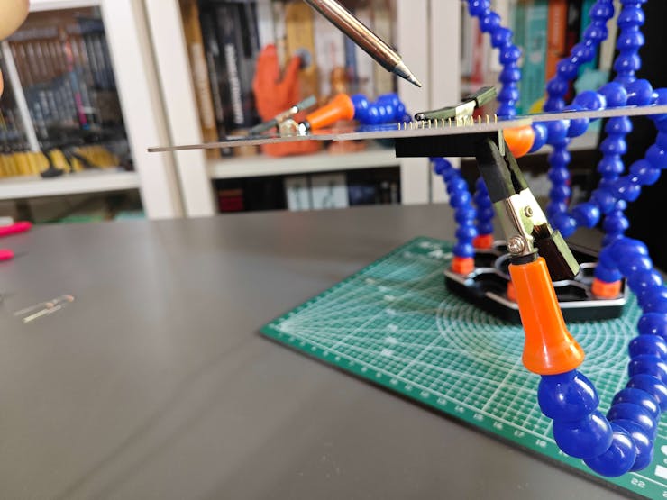
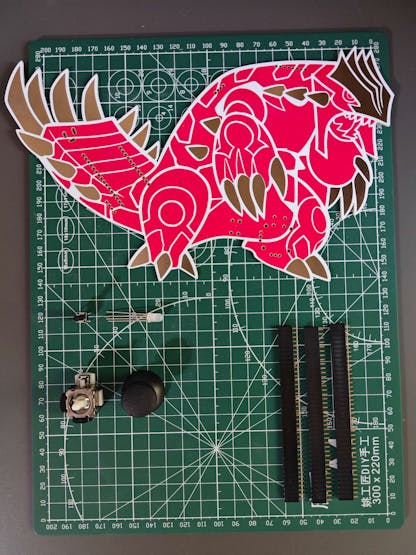
Before prototyping my Kyogre-inspired PCB design, I inspected the detailed pin reference of XIAO ESP32C6 and needed to prepare components requiring soldering for programming. Aside from the other components, I employed a soldering station to solder jumper wires to each leg of the micro switch in order to make it compatible with the custom switch connector on the CNC router, which will be explained in the following steps.
![]()
![]()
![]()
![]()
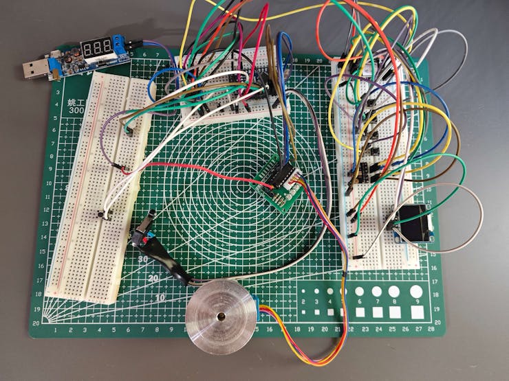
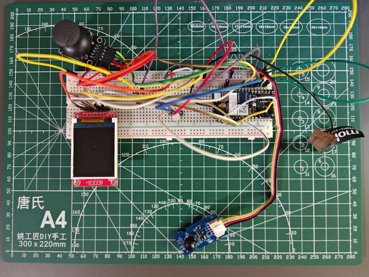
Then, I checked the wireless (Wi-Fi) and serial communication quality between XIAO ESP32C6, Arduino Nano, and the web dashboard (application) while transferring and receiving data packets. In the meantime, I also tested the torque capacity of the 28BYJ-48 stepper motor.
![]()
![]()
I designed my Kyogre-inspired PCB by utilizing Autodesk Fusion 360 and KiCad in tandem. Since I wanted to design a unique 3D-printed encasement to simplify the PCB integration to the special mounts (also 3D-printed) of the aluminum water cooling radiator, I created the PCB outline (edge) on Fusion 360 and then imported the outline file (DXF) to KiCad. In this regard, I was able to design custom 3D parts compatible with the PCB outline precisely.
To replicate this malfunction detection device for water-cooled HVAC systems, you can download the Gerber file below or order the discussed PCB design directly from my ELECROW community page.
![]()
![]()
![]()
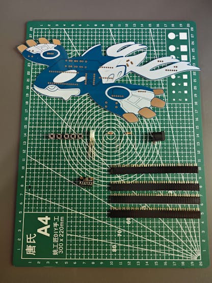
By utilizing a TS100 soldering iron, I attached the component list depicted below.
📌 Component list of the Kyogre PCB:
L_1, L_2 (Headers for XIAO ESP32C6)
A1 (Headers for Arduino Nano)
Mic1 (Fermion: I2S MEMS Microphone)
SSD1306 (Headers for SSD1306 OLED Display)
L1 (Headers for Bi-Directional Logic Level Converter)
SW1 (Micro Switch (JL024-2-026))
ULN2003 (Headers for 28BYJ-48 Stepper Motor)
R1 (20K Resistor)
R2 (220Ω Resistor)
C1, C2, C3, C4, K1 (6x6 Pushbutton)
D1 (5 mm Common Anode RGB LED)
J2 (Headers for Additional Stepper Motor Power Supply)
J1 (Power Jack)
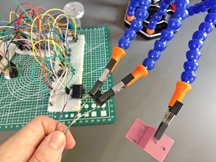
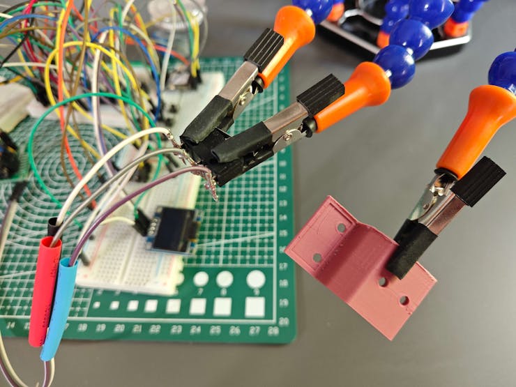
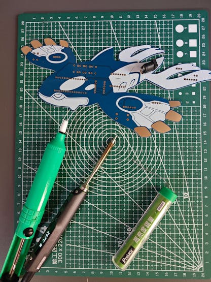
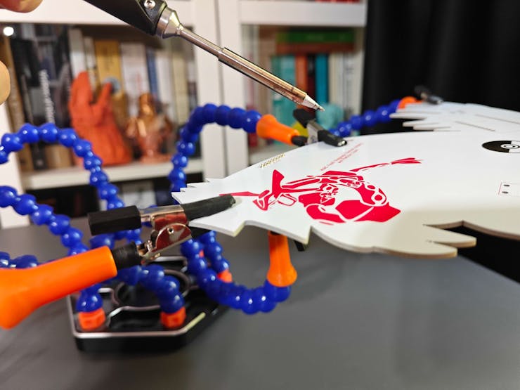
Since some components were tricky to solder due to the unique structure of the Kyogre PCB, I utilized the soldering station to hold the problematic parts.
![]()
![]()
![]()
![]()
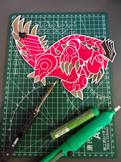
After concluding soldering all components, I tested whether the Kyogre PCB operated as expected or was susceptible to electrical issues.
![]()
-
4Step 1.a.1: Making connections and adjustments on the Kyogre PCB
// Connections// XIAO ESP32C6 :
//                                Fermion: I2S MEMS Microphone
// 3.3V    ------------------------ 3V3
// D1      ------------------------ WS (+20K)
// 3.3V    ------------------------ SEL
// D0      ------------------------ SCK
// D2      ------------------------ DO (+220Ω)
//                                SSD1306 OLED Display (128x64)
// D4/SDA  ------------------------ SDA
// D5/SCL  ------------------------ SCL
//                                Control Button (A)
// D8      ------------------------ +
//                                Control Button (B)
// D9      ------------------------ +
//                                Control Button (C)
// D10     ------------------------ +
//                                Control Button (D)
// D3      ------------------------ +
//                                Arduino Nano
// RX (D7) ------------------------ TX (D4)
// TX (D6) ------------------------ RX (D2)
&
&
&
// Connections
// Arduino Nano :
//                                28BYJ-48 Stepper Motor (w/ ULN2003)
// D8      ------------------------ IN1
// D9      ------------------------ IN2
// D10     ------------------------ IN3
// D11     ------------------------ IN4
//                                Micro Switch with Pulley (JL024-2-026)
// D12     ------------------------ +
//                                Home Button
// D7     ------------------------ +
//                                5mm Common Anode RGB LED
// D3      ------------------------ R
// D5      ------------------------ G
// D6      ------------------------ B
//                                XIAO ESP32C6
// RX (D2) ------------------------ TX (D6)
// TX (D4) ------------------------ RX (D7)
#️⃣ Since XIAO ESP32C6 is a feature-rich development board providing an I2S port, I was able to connect a Fermion I2S MEMS microphone to collect raw audio buffers easily. Nevertheless, after conducting some experiments, I noticed the produced audio buffers were noisy or completely inaccurate. Therefore, I added additional resistors to the WS (+20K) and DO (+220Ω) pins of the I2S microphone. Then, I managed to obtain precise raw audio buffers.
#️⃣ To provide the user with a feature-packed interface, I connected an SSD1306 OLED display and four control buttons to XIAO ESP32C6. I also connected an RGB LED to Arduino Nano to inform the user of the CNC router status while performing operations according to the CNC commands transferred by XIAO ESP32C6.
#️⃣ Since Arduino Nano operates at 5V and XIAO ESP32C6 requires 3.3V logic level voltage, their pins cannot be connected directly, even for serial communication. Therefore, I utilized a bi-directional logic level converter to shift the voltage for the connections between XIAO ESP32C6 and Arduino Nano.
#️⃣ To control the CNC router effortlessly, I connected a 28BYJ-48 stepper motor to Arduino Nano via its built-in ULN2003 driver module. Since I wanted to implement automatic homing sequence to the CNC router, I connected a micro switch with pulley (JL024-2-026) to Arduino Nano, similar to a 3D printer switch.
#️⃣ Since the 28BYJ-48 stepper motor can be current-demanding on full load, I connected an additional 5V battery to supply the stepper motor without damaging other components.
![]()
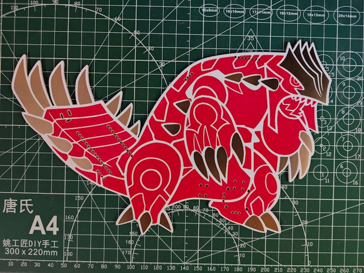
Step 1.b: Designing and soldering the Groudon-inspired PCB
Before prototyping my Groudon-inspired PCB design, I inspected the detailed pin reference of Particle Photon 2 and needed to prepare components requiring soldering for programming.
Then, I checked the wireless (Wi-Fi) and cloud communication quality between Photon 2, the Particle Cloud, and the web dashboard (application) while transferring and receiving data packets.
![]()
![]()
I designed my Groudon-inspired PCB by utilizing Autodesk Fusion 360 and KiCad in tandem. Since I wanted to design a unique 3D-printed encasement to simplify the PCB integration to the custom CNC router (also 3D-printed) moving the thermal camera container head, I created the PCB outline (edge) on Fusion 360 and then imported the outline file (DXF) to KiCad. In this regard, I was able to design custom 3D parts compatible with the PCB outline precisely.
To replicate this malfunction detection device for water-cooled HVAC systems, you can download the Gerber file below or order the discussed PCB design directly from my ELECROW community page.
![]()
![]()
![]()
By utilizing a TS100 soldering iron, I attached the component list depicted below.
📌 Component list of the Groudon PCB:
Photon2 (Headers for Particle Photon 2)
MLX90641 (Headers for MLX90641 Thermal Imaging Camera)
ST7735 (Headers for ST7735 1.8" TFT Display)
U1 (COM-09032 Analog Joystick)
K1 (6x6 Pushbutton)
D1 (5 mm Common Anode RGB LED)
J1 (Power Jack)
Since some components were tricky to solder due to the unique structure of the Groudon PCB, I utilized the soldering station to hold the problematic parts.
![]()
![]()
![]()
After concluding soldering all components, I tested whether the Groudon PCB operated as expected or was susceptible to electrical issues.
![]()
-
5Step 1.b.1: Making connections and adjustments on the Groudon PCB
// Connections
// Particle Photon 2 :
//                                MLX90641 Thermal Imaging Camera (16x12 w/ 110° FOV)
// D1 / SCL   --------------------- SCL
// D0 / SDA   --------------------- SDA
//                                ST7735 1.8" Color TFT Display
// 3.3V --------------------------- LED
// D17 / SCK  --------------------- SCK
// D15 / MOSI --------------------- SDA
// D3   --------------------------- AO (DC)
// D4   --------------------------- RESET
// D2   --------------------------- CS
// GND  --------------------------- GND
// 3.3V --------------------------- VCC
//                                COM-09032 Analog Joystick
// A0   --------------------------- VRX
// A1   --------------------------- VRY
// D19  --------------------------- SW
//                                Control Button (OK)
// D9   --------------------------- +
//                                5mm Common Anode RGB LED
// D13  --------------------------- R
// D14  --------------------------- G
// D5   --------------------------- B
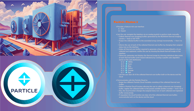
#️⃣ Since Particle Photon 2 is a capable IoT development board providing Particle Cloud compatibility out of the box, I was able to set up cloud variables and functions effortlessly to communicate with Photon 2 via the Particle Cloud API through the web dashboard.
#️⃣ To obtain accurate thermal scan (imaging) buffers, I connected an MLX90641 thermal imaging camera to Photon 2 via a Grove 4-pin connection cable. Since the MLX90641 camera produces 16x12 IR arrays (buffers) with fully calibrated 110° FOV (field-of-view), I was able to generate considerably large thermal images by combining four sequential buffers and adjusting pixel size.
#️⃣ Although Photon 2 is a powerful development board, it is not suitable for generating thermal images, saving image samples, and running a demanding visual anomaly detection model simultaneously due to memory limitations. Therefore, the web dashboard, hosted by LattePanda Mu, handles all of the mentioned operations after Photon 2 registers the produced thermal scan (imaging) buffers to the associated Particle Cloud variables.
#️⃣ To provide the user with a feature-rich interface, I connected an ST7735 TFT display and a COM-09032 analog joystick to Photon 2. I also added an RGB LED to inform the user of the device status while performing operations related to thermal buffer collection and registration.
![]()
-
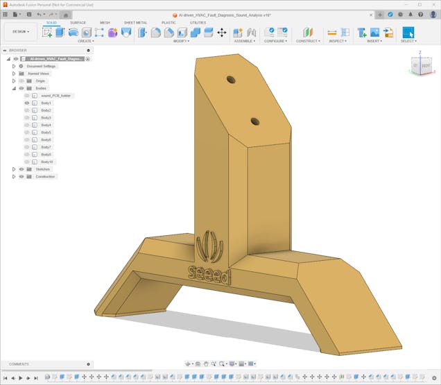
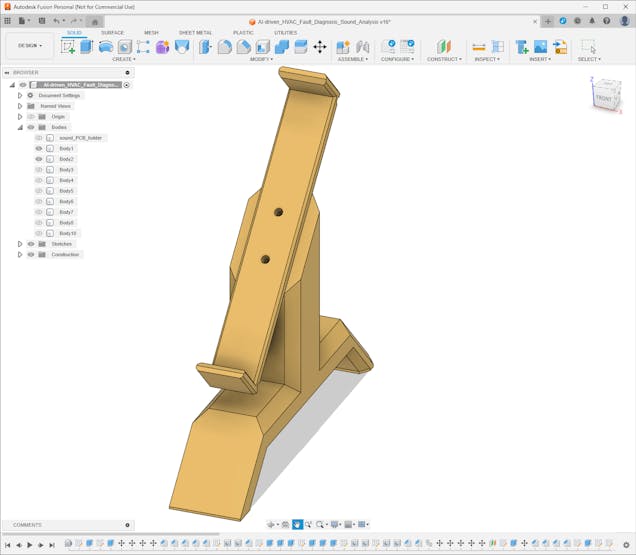
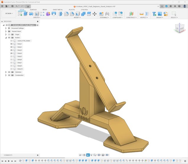
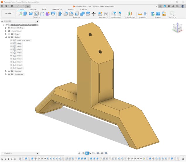
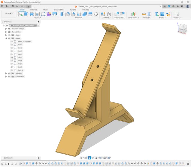
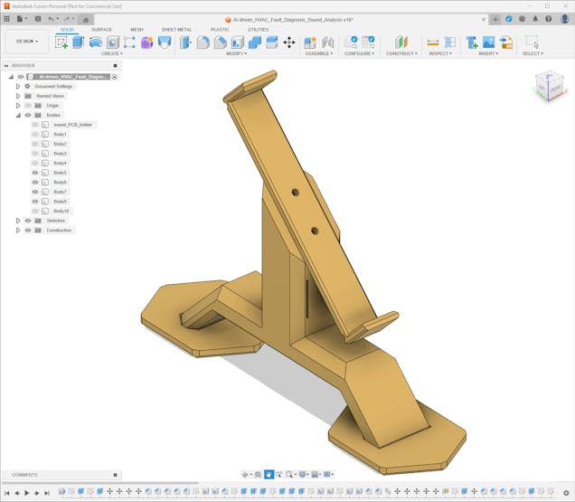
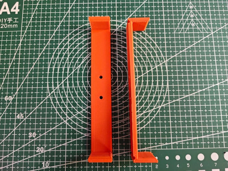
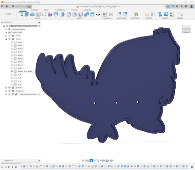
6Step 2.a: Designing and printing the aluminum radiator mounts and the Kyogre PCB encasement
Since I focused on building a versatile and accessible AI-driven device that identifies the faulty cooling components via anomalous sound detection and diagnoses ensuing thermal cooling malfunctions via visual anomaly detection based on thermal images, I decided to design complementary 3D-printable parts that improve the robustness, compatibility, and capabilities of the device considering harsh operating conditions of industrial plants.
First, I wanted to fix the large aluminum radiator position and integrate the Kyogre PCB as close as possible to the radiator. Thus, I designed these parts:
- the main body of the right radiator mount,
- the main body of the left radiator mount,
- two tilted snap-fit joints perfectly sized for the radiator,
- four special legs (back and front) supporting the radiator mounts,
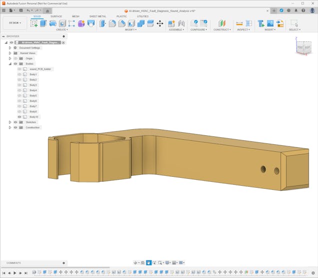
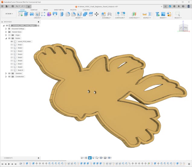
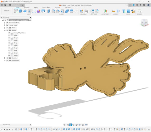
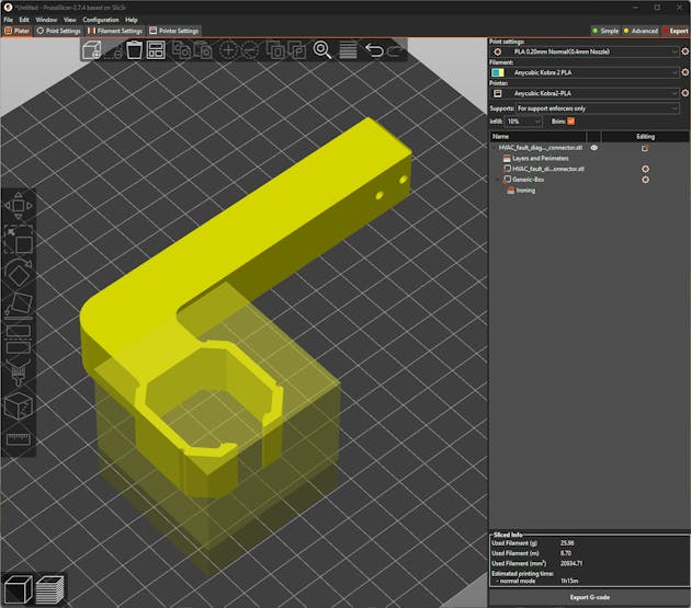
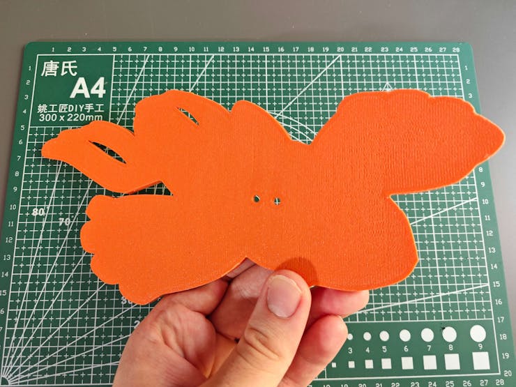
- the unique PCB encasement derived from the Kyogre PCB outline,
- the PCB encasement connector providing a buckle-shaped joint interlocking with the right radiator mount.
Furthermore, I decided to emboss the Seeed logo on the main body of the left radiator mount to highlight the qualifications of this segment of the AI-powered HVAC malfunction detection device.
I utilized Autodesk Fusion 360 to model all of the mentioned 3D-printable parts and test their clearances to print flawless joints. For further examination, you can download their STL files below.
![]()
![]()
![]()
![]()
![]()
![]()
![]()
![]()
![]()
![]()
![]()
![]()
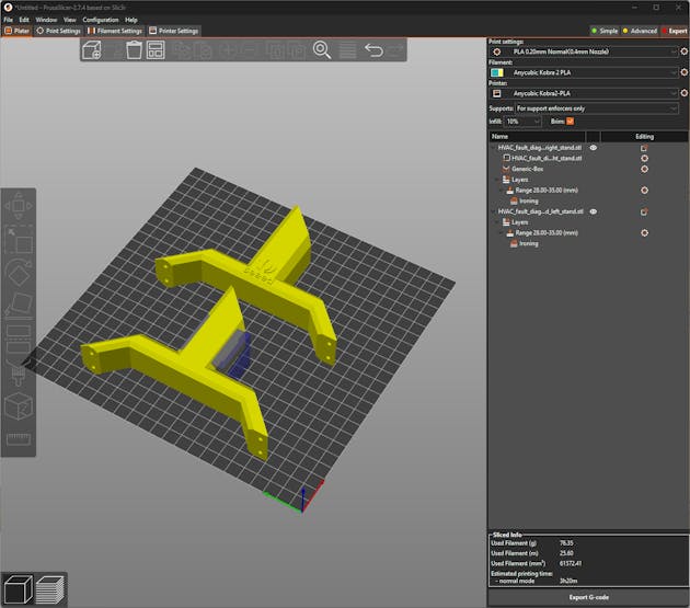
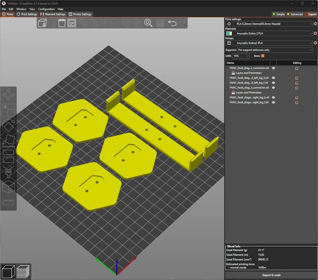
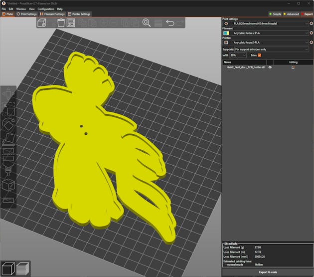
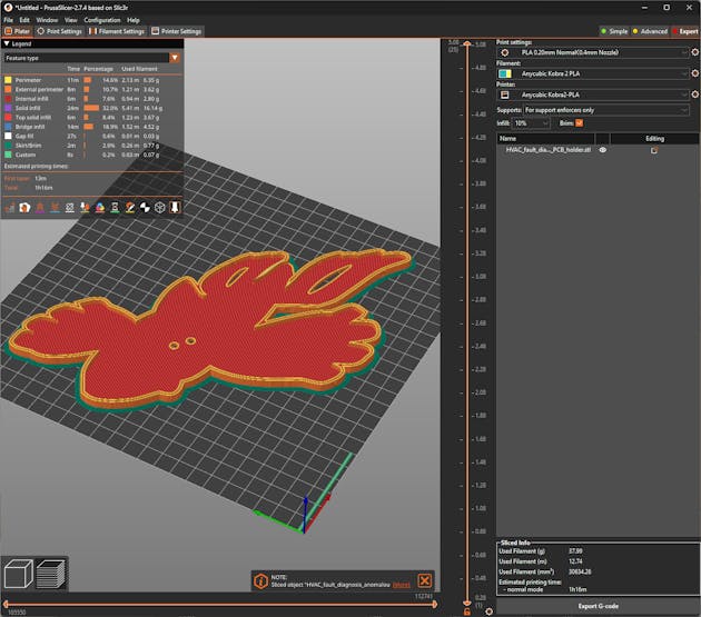
After designing 3D models and exporting them as STL files, I sliced the exported models in PrusaSlicer, which provides lots of groundbreaking features such as paint-on supports and height range modifiers.
![]()
![]()
![]()
![]()
![]()
![]()
![]()
![]()
Since I wanted to apply a unique industrial theme representing vivid industrial processes, I utilized this PLA filament:
- ePLA-Matte Tangerine
Finally, I printed all of the mentioned models with my Anycubic Kobra 2 3D Printer.
![]()
-
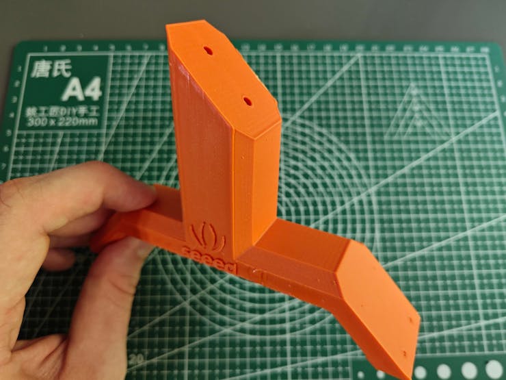
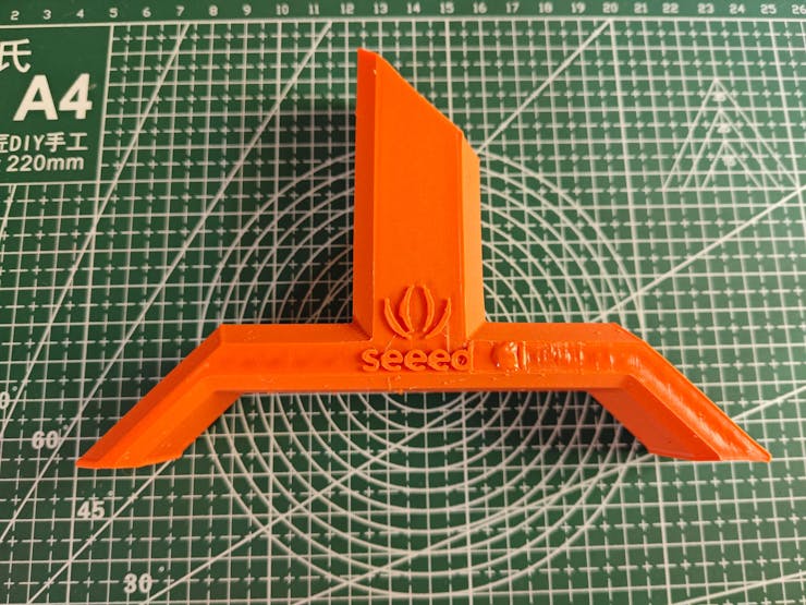
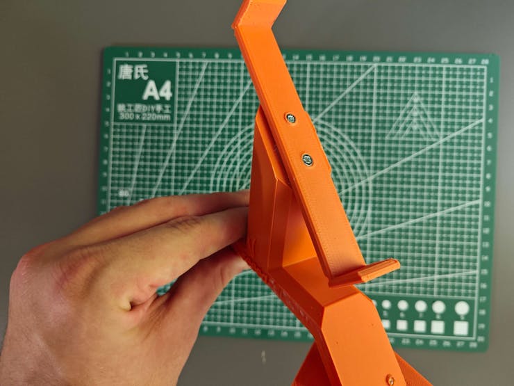
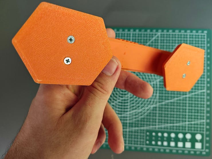
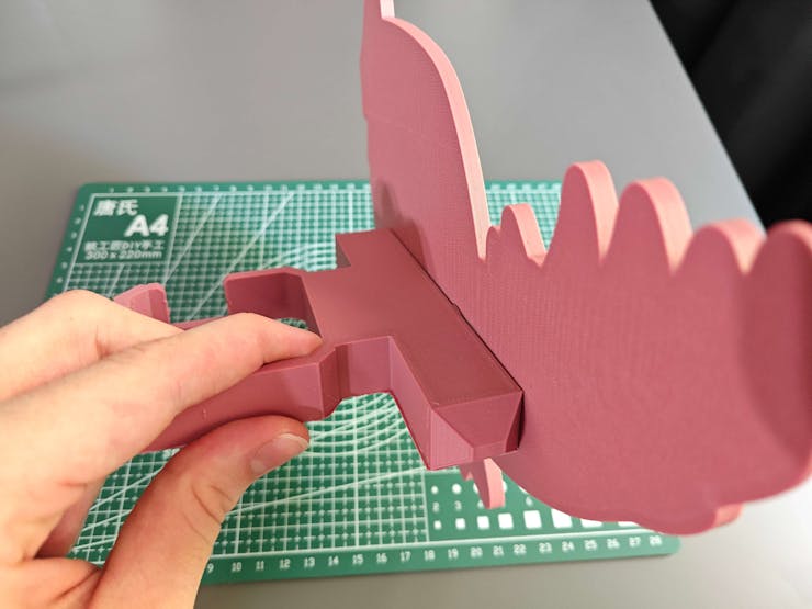
7Step 2.a.1: Assembling the 3D-printed components
After printing all 3D models related to the aluminum radiator, I started to combine the radiator mount parts via M3 screws through the assembly-ready screw holes.
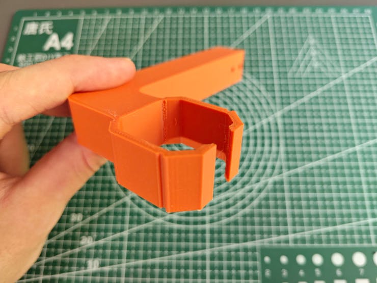
Then, I fastened the unique Kyogre PCB encasement to the complementary PCB connector via M3 screws. Since the PCB connector is compatible with the right radiator mount via its buckle-shaped snap-fit joint, I was able to interlock the PCB connector with the right mount body effortlessly.
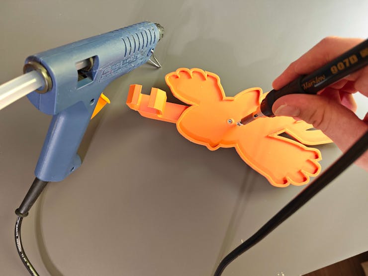
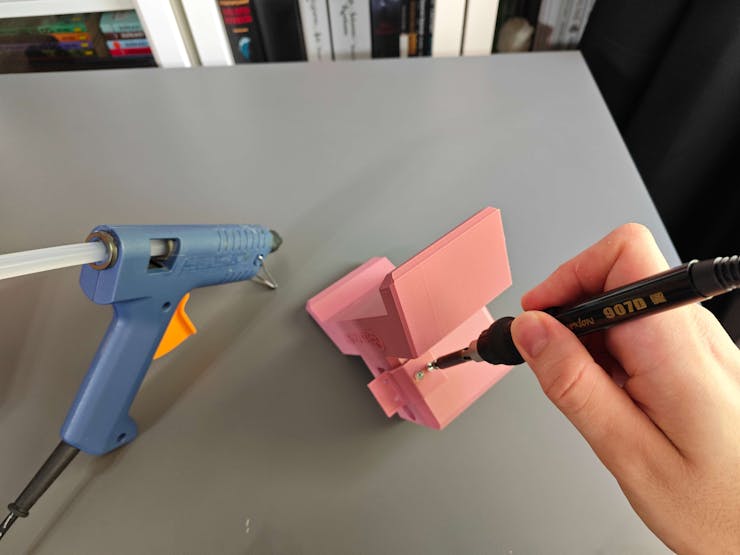
Although I applied hot glue between parts while affixing them via M3 screws, it was still not enough to build a production-ready device, especially considering the harsh operating conditions of industrial HVAC systems. Thus, I employed a well-known injection molding technique to make the connections more sturdy. In this technique, a heat press mechanism is generally utilized to add threaded brass inserts between 3D-printed parts to connect them firmly. In my version, I simply used a soldering iron to embed M3 screws directly into the assembly-ready holes instead of threaded inserts to fasten the parts together.
![]()
![]()
![]()
![]()
![]()
![]()
![]()
![]()
![]()
![]()
![]()
As discussed earlier, I employed the soldering iron to embed M3 screws directly into the assembly-ready holes to affix parts tightly.
![]()
![]()
![]()
![]()
![]()
![]()
![]()
![]()
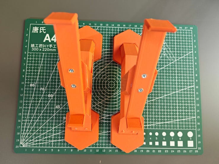
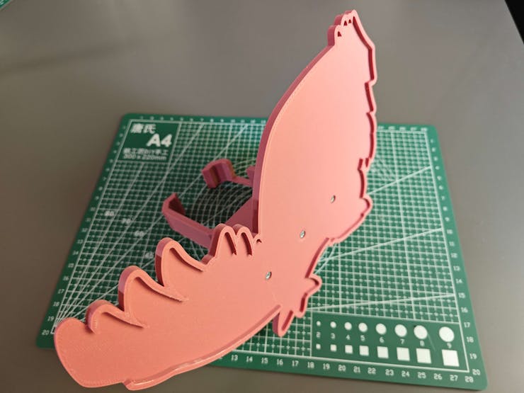
After combining all the parts, I placed the aluminum radiator on the radiator mounts via their bracket-shaped snap-fit joints in order to test the strength of the mounts while carrying the radiator in a tilted position.
![]()
-
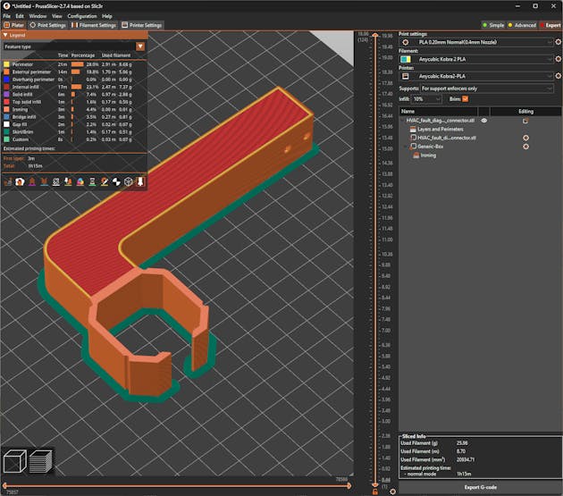
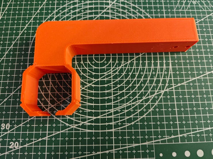
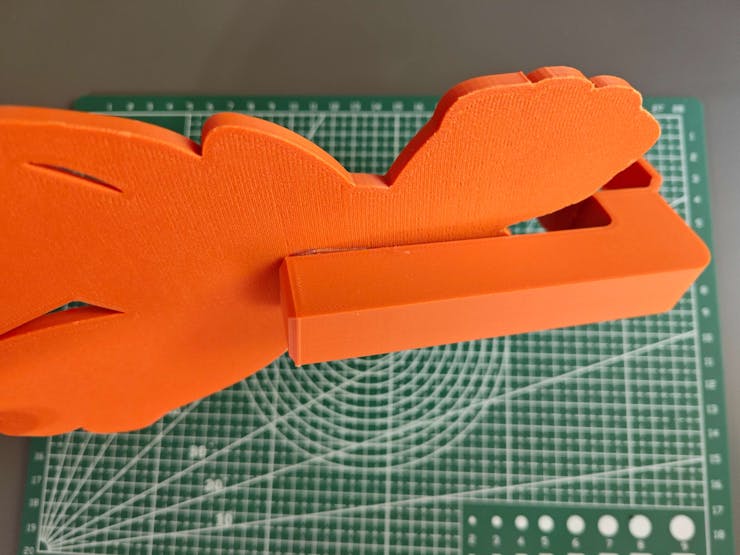
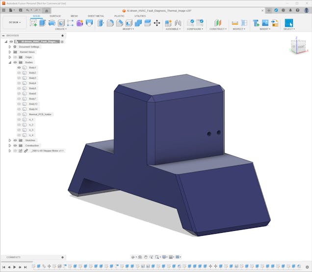
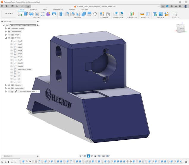
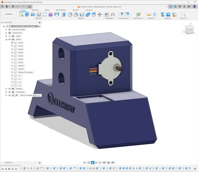
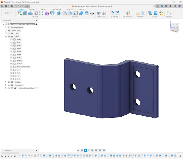
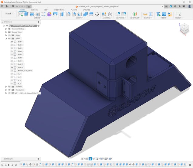
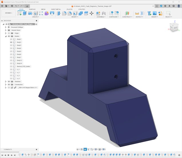
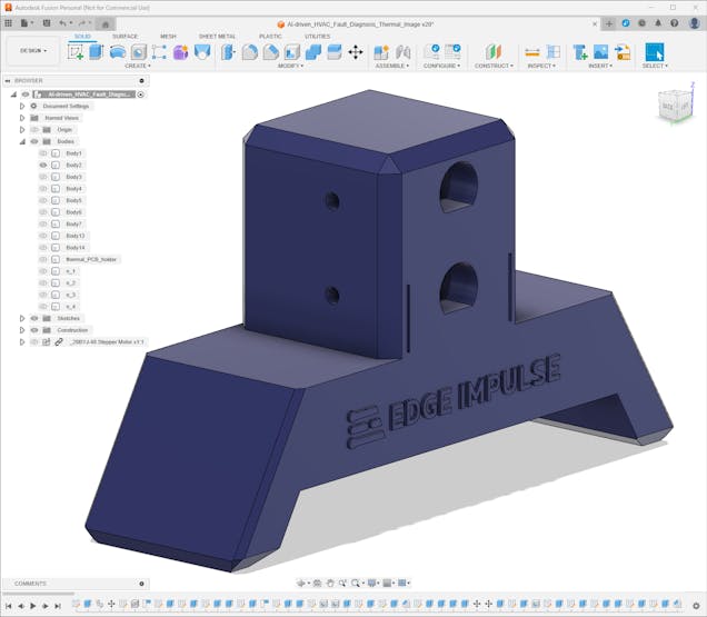
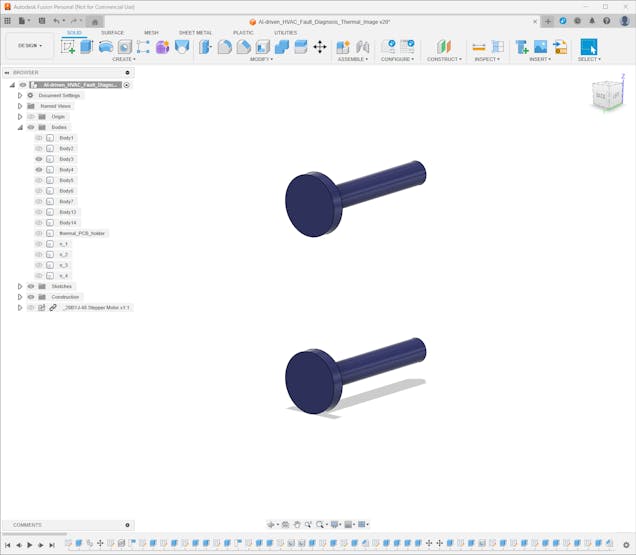
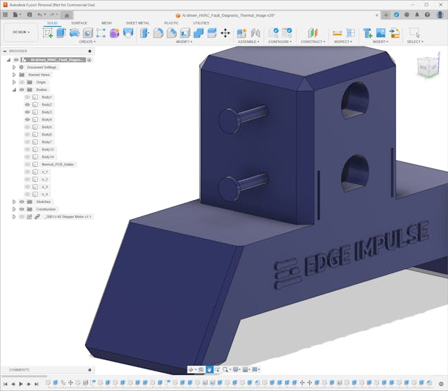
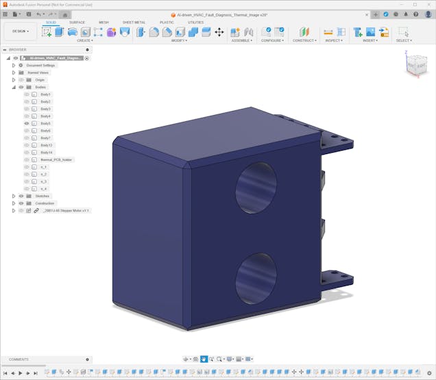
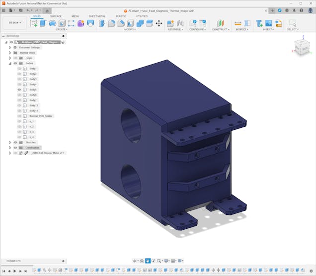
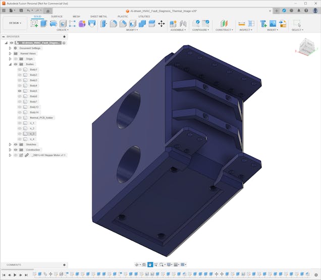
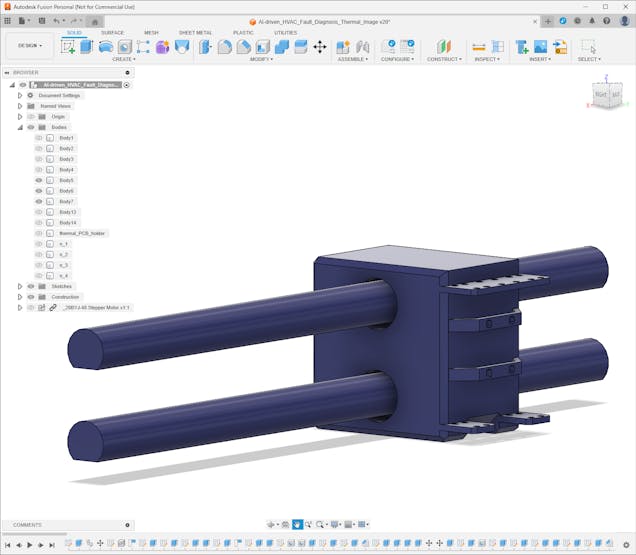
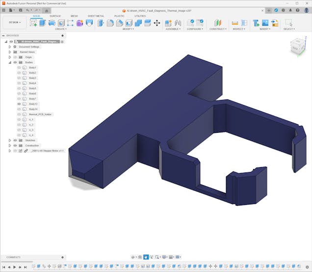
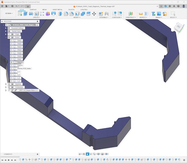
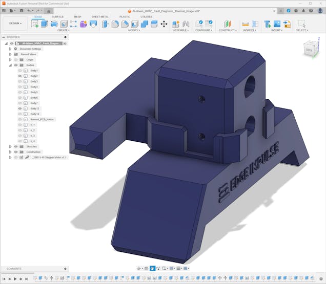
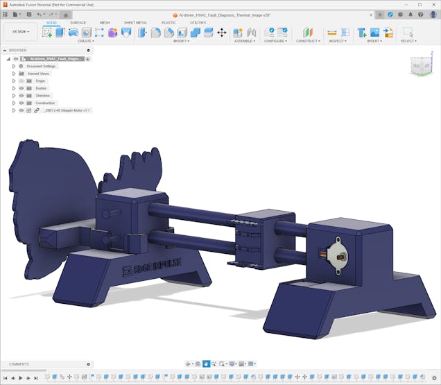
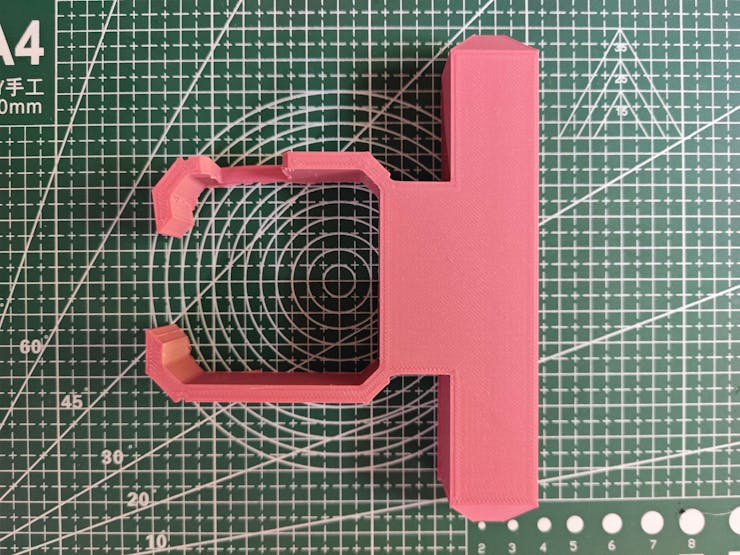
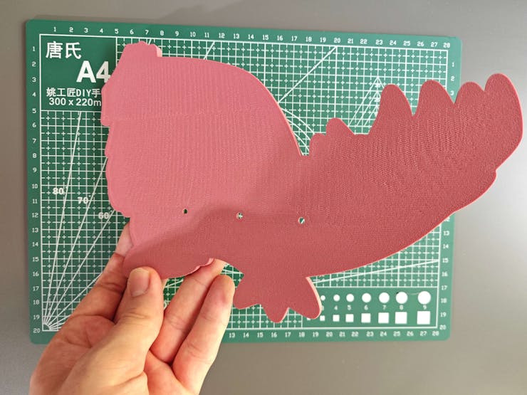
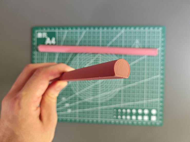
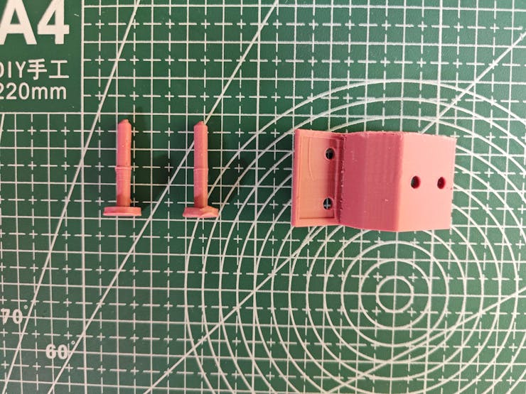
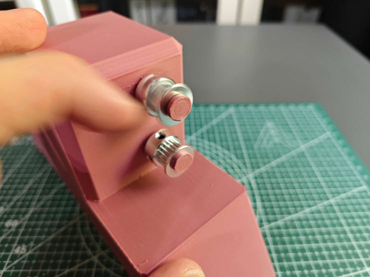
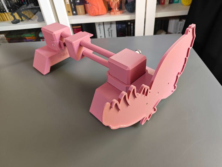
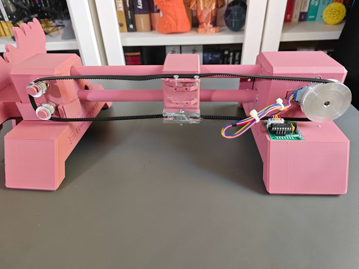
8Step 2.b: Designing and printing the CNC router moving the thermal camera and the Groudon PCB encasement
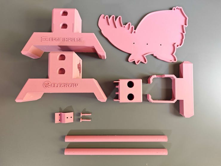
After modeling the 3D parts related to the aluminum radiator, I focused on designing a custom CNC router to move the thermal imaging camera to collect thermal scan (imaging) buffers from the predefined locations on the aluminum cooling blocks to produce an accurate thermal image. Also, I wanted to integrate the Groudon PCB as close as possible to the CNC router since the MLX90641 thermal imaging camera must be connected to Photon 2. Thus, I designed these parts:
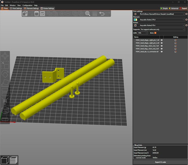
- two chamfered CNC rods,
- the micro switch connector,
- two special pins for attaching GT2 20T pulleys,
- the left CNC stand providing slots for the CNC rods, the 28BYJ-48 stepper motor, the ULN2003 driver board, and the micro switch connector,
- the right CNC stand providing slots for the CNC rods and the GT2 20T pulley pins,
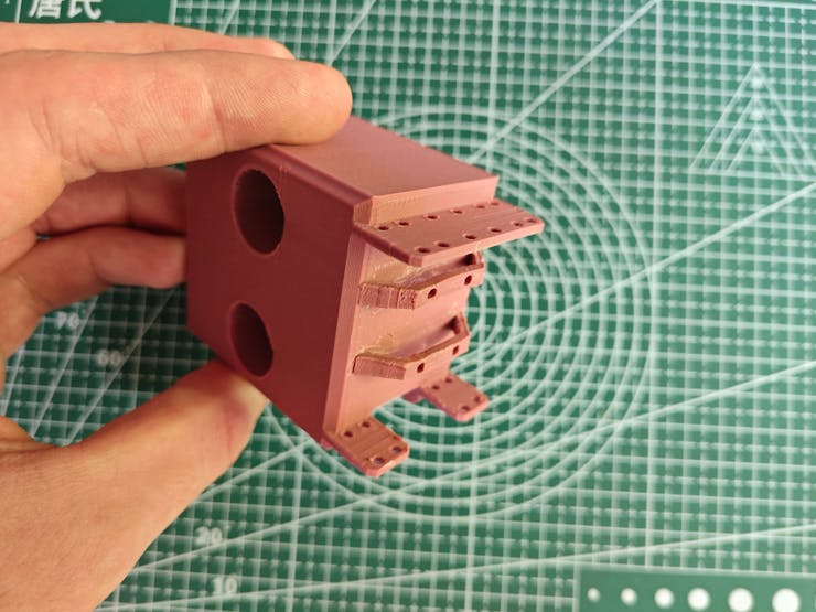
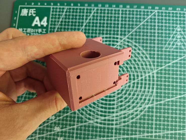
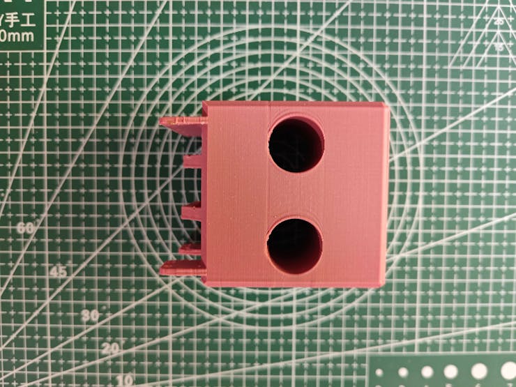
- the thermal camera container head providing holes to pass CNC rods and slots for the MLX90641 thermal imaging camera, GT2 timing belt, and aluminum gear clamps,
- the unique PCB encasement derived from the Groudon PCB outline,
- the PCB encasement connector providing a buckle-shaped joint interlocking with the right CNC stand while preventing any contact with the embedded GT2 20T pulley pins.
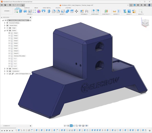
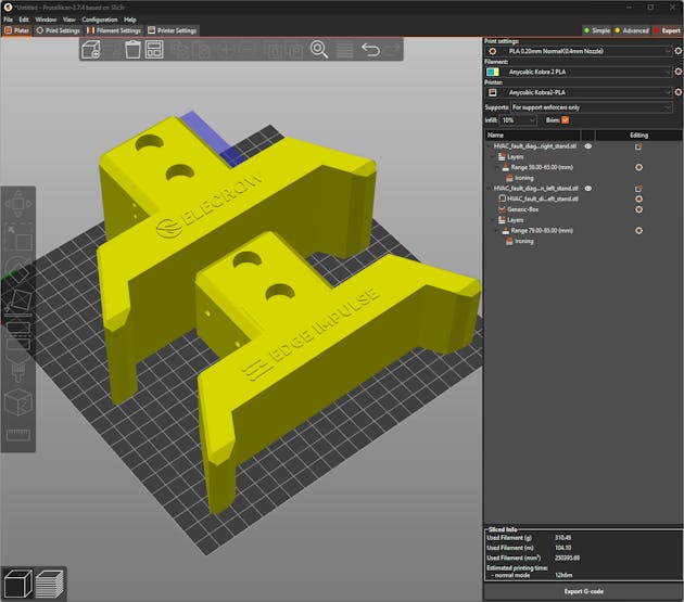
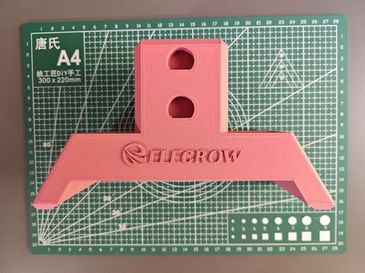
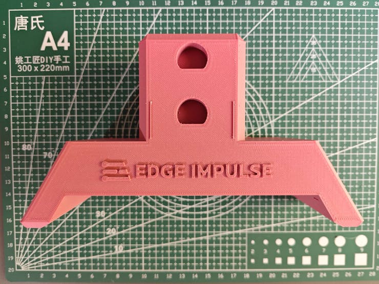
Furthermore, I decided to emboss the Elecrow logo and the Edge Impulse logo on the left and right CNC stands respectively to highlight the qualifications of this segment of the AI-powered HVAC malfunction detection device.
I utilized Autodesk Fusion 360 to model all of the mentioned 3D-printable parts and test their clearances to print flawless joints. For further examination, you can download their STL files below.
![]()
![]()
![]()
![]()
![]()
![]()
![]()
![]()
![]()
![]()
![]()
![]()
![]()
![]()
![]()
![]()
![]()
![]()
![]()
![]()
![]()
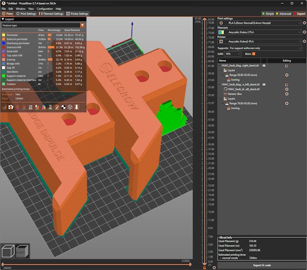
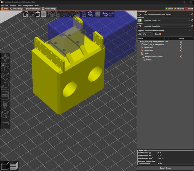
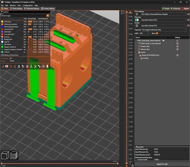
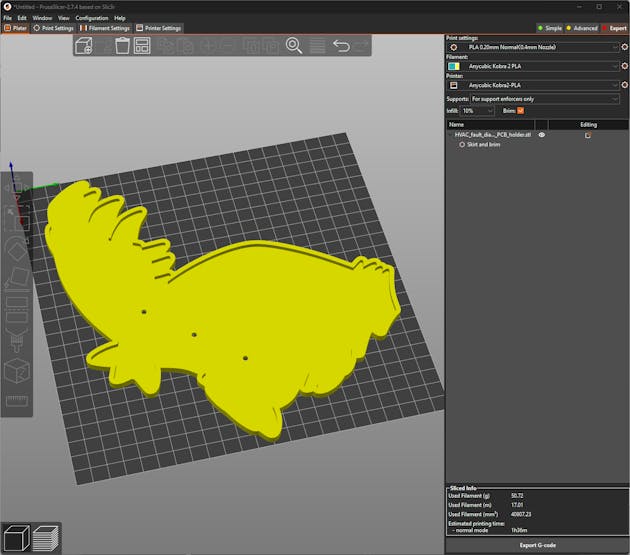
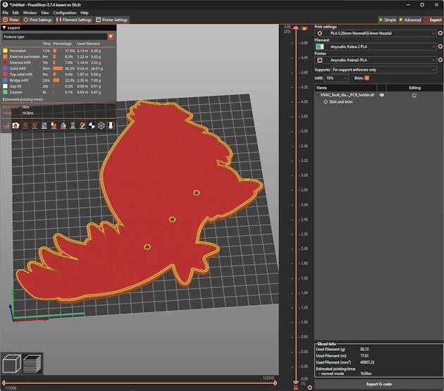
After designing 3D models and exporting them as STL files, I sliced the exported models in PrusaSlicer, which provides lots of groundbreaking features such as paint-on supports and height range modifiers.
![]()
![]()
![]()
![]()
![]()
![]()
![]()
![]()
![]()
![]()
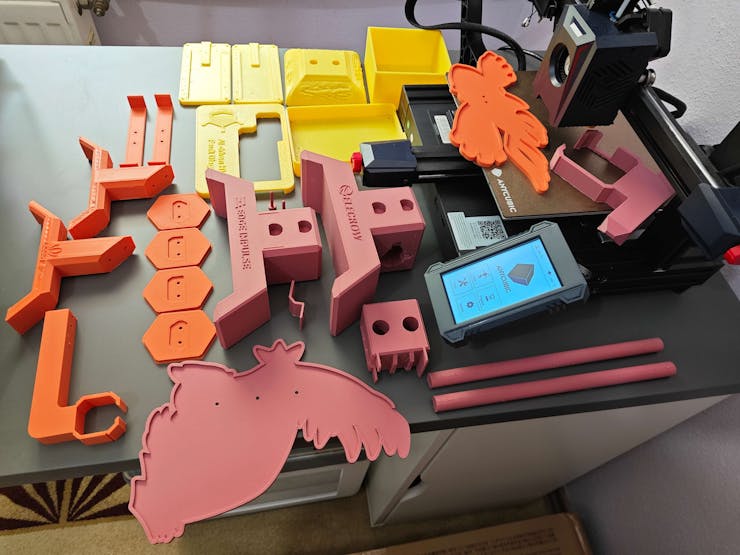
Since I wanted to apply a unique industrial theme representing vivid industrial processes, I utilized this PLA filament contrasting with the previous filament color:
- ePLA-Matte Morandi Purple
Finally, I printed all of the mentioned models with my Anycubic Kobra 2 3D Printer.
![]()
-
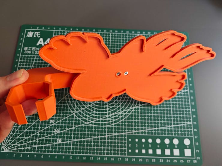
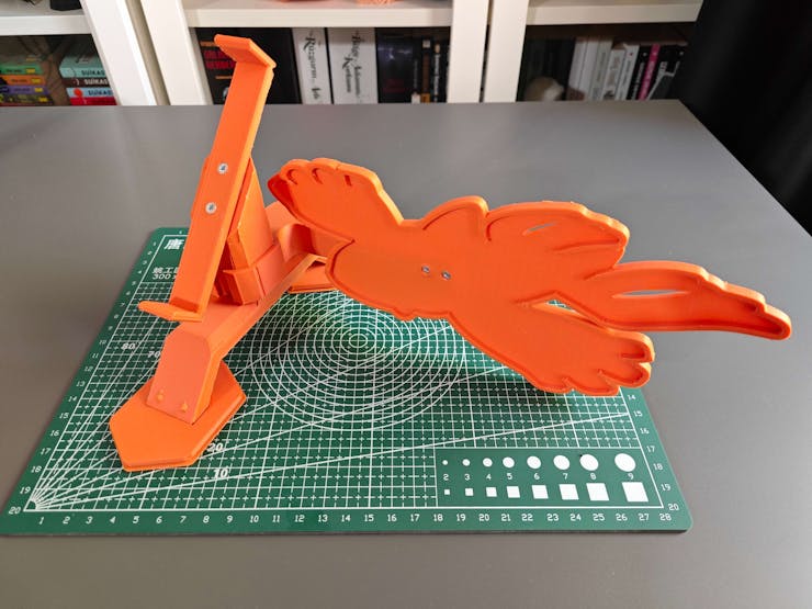
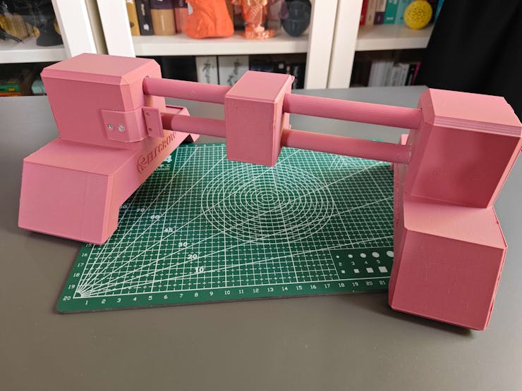
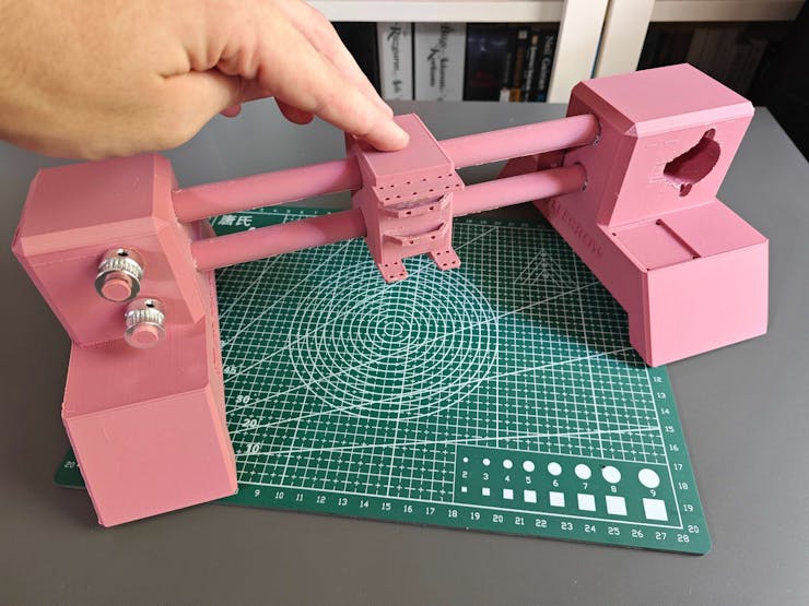
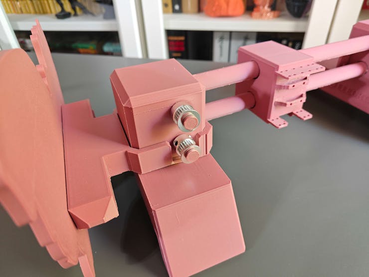
9Step 2.b.1: Assembling the 3D-printed components
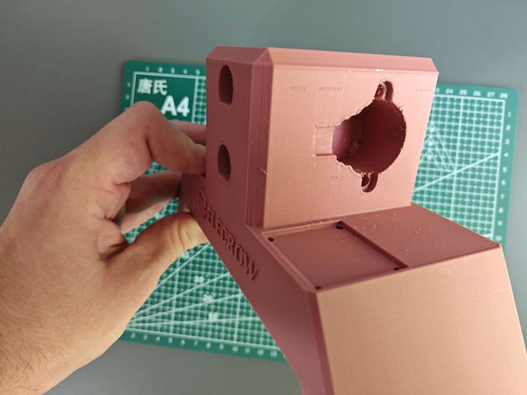
After printing all 3D models related to the custom CNC router, I started to combine the CNC parts via M3 screws through the assembly-ready screw holes and the provided slots for the associated parts.
Then, I fastened the unique Groudon PCB encasement to the complementary PCB connector via M3 screws. Since the PCB connector is compatible with the right CNC stand via its buckle-shaped snap-fit joint and avoids any contact with the GT2 20T pulley pins, I was able to interlock the PCB connector with the right CNC stand effortlessly.
Although I applied hot glue between parts while affixing them via M3 screws, it was still not enough to build a production-ready device, especially for a constantly moving CNC router. Thus, I employed a well-known injection molding technique to make the connections more sturdy. In this technique, a heat press mechanism is generally utilized to add threaded brass inserts between 3D-printed parts to connect them firmly. In my version, I simply used a soldering iron to embed M3 screws directly into the assembly-ready holes instead of threaded inserts to fasten the parts together.
![]()
![]()
![]()
![]()
![]()
![]()
![]()
![]()
![]()
![]()
![]()
![]()
![]()
![]()
![]()
As discussed earlier, I employed the soldering iron to embed M3 screws directly into the assembly-ready holes to affix parts tightly.
For the parts with provided slots, I utilized the hot glue gun to reinforce the connections.
![]()
![]()
![]()
![]()
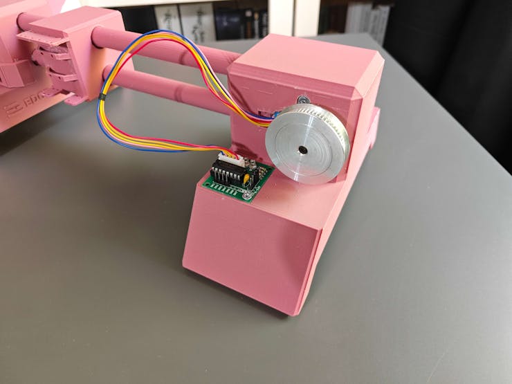
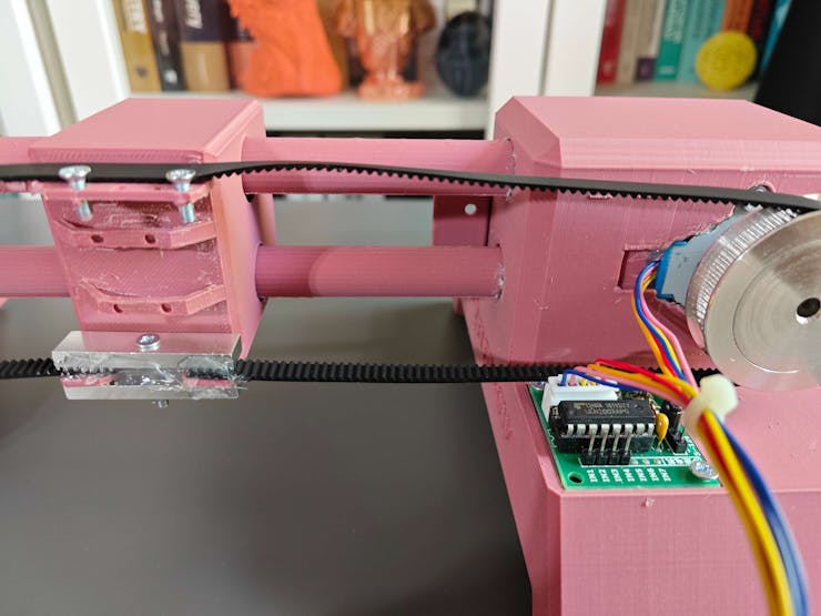
Before finalizing all slot connections via the hot glue gun, I started to work on building the positioning mechanism of the CNC router by integrating these mechanical components into their corresponding slots:
- a 28BYJ-48 stepper motor,
- a ULN2003 driver board,
- a GT2 60T pulley attached to the stepper motor,
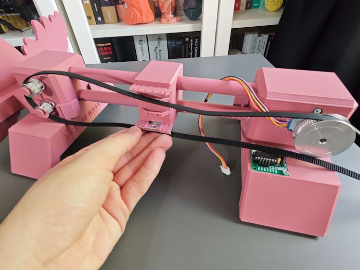
- two GT2 20T pulleys attached to the special pulley pins,
- GT2 6 mm timing belt,
- two GT2 aluminum gear clamps.
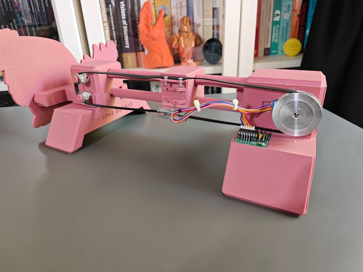
After affixing the timing belt via the gear clamps, I utilized two M3 screws to adjust the tightness of the timing belt.
![]()
![]()
![]()
![]()
![]()
![]()
![]()
![]()
![]()
![]()
![]()
-
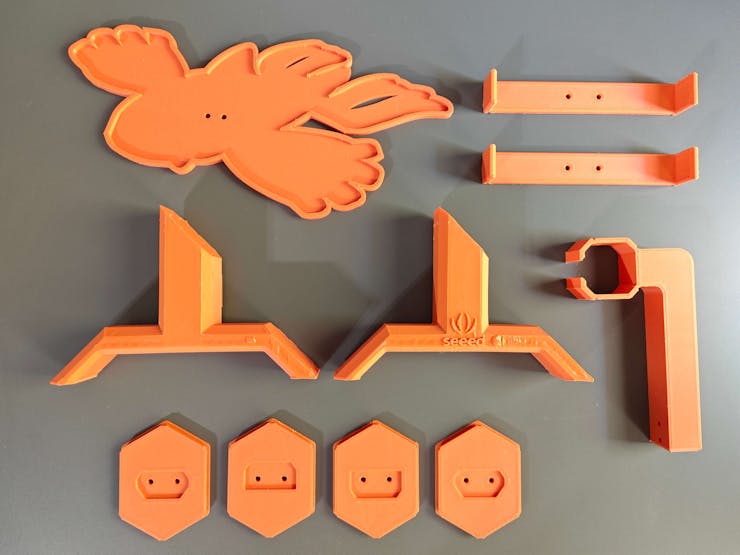
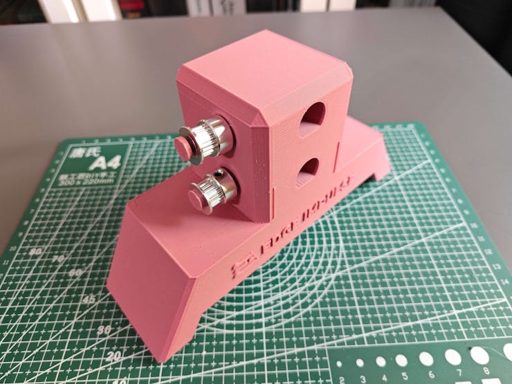
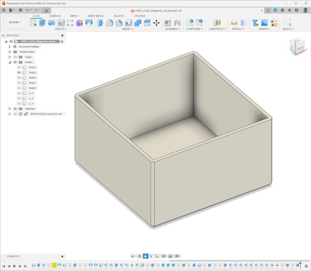
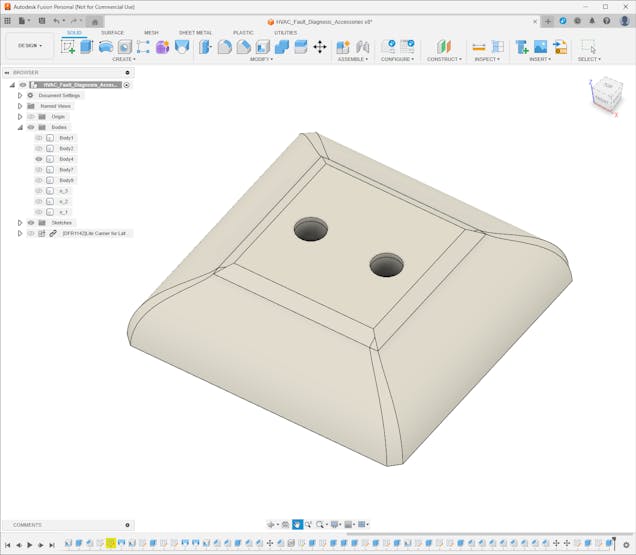
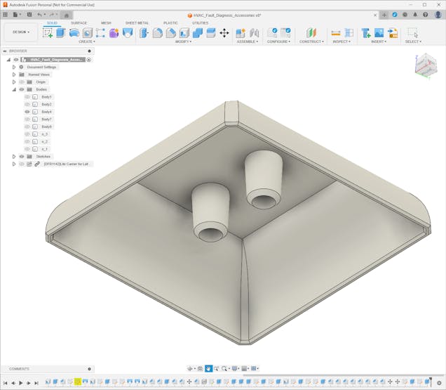
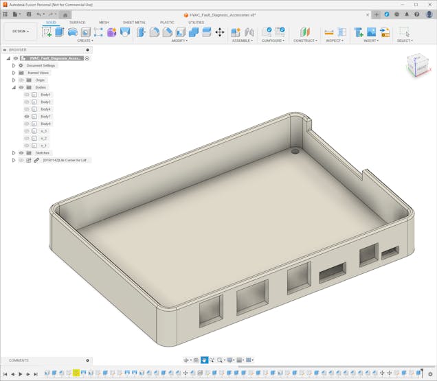
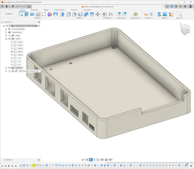
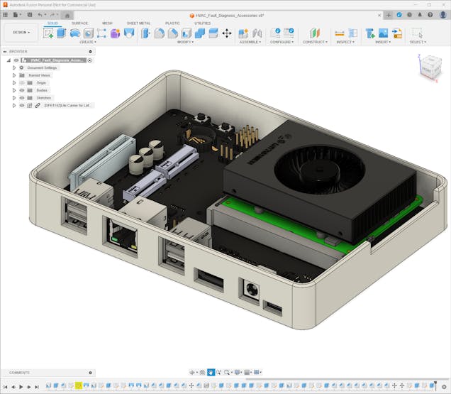
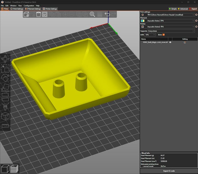
10Step 2.c: Designing and printing the water-cooled HVAC system accessories
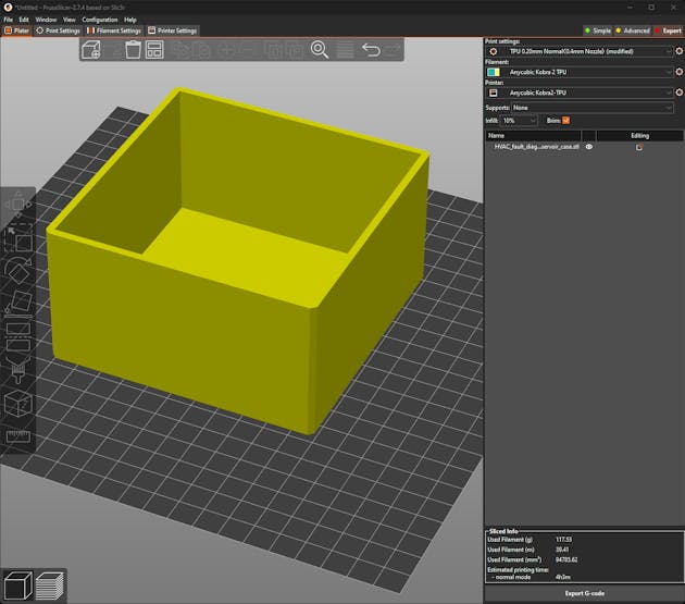
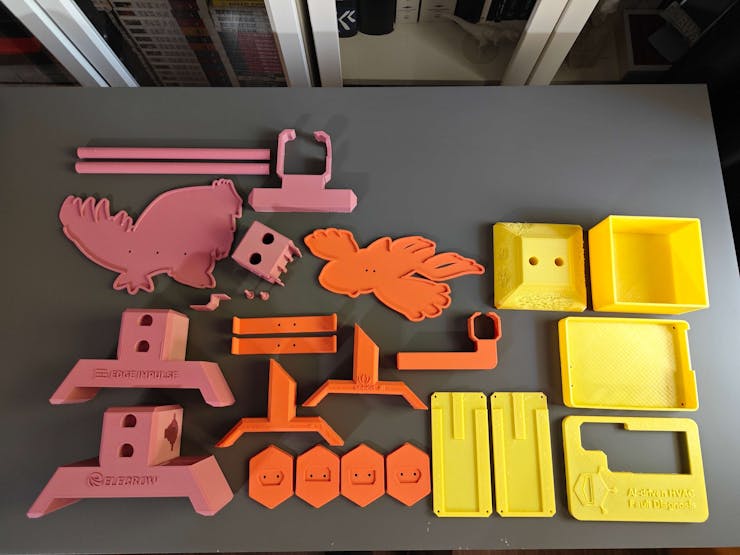
After modeling the 3D parts related to the custom CNC router, I realized that my overall design was still lacking some of the features I wanted to implement to build an industrial-level HVAC malfunction detection device, such as an impervious custom reservoir for the simplified water cooling system. Thus, I designed these additional parts:
- an aluminum cooling block holder allowing plastic tubing adjustment,
- an impermeable water reservoir compatible with the water cooling pump,
- a removable top cover for the reservoir with built-in plastic tubing fittings — IN and OUT,
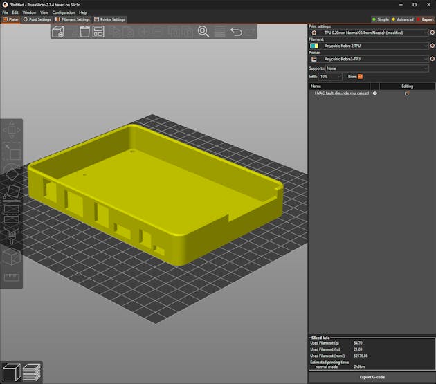
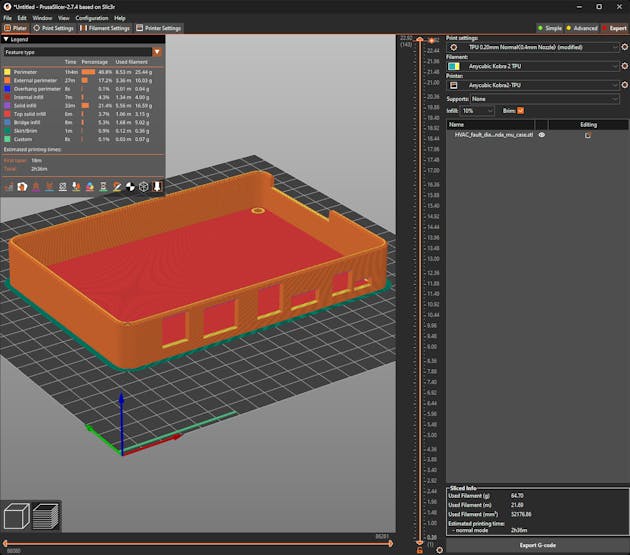
- a custom case and a removable top cover for LattePanda Mu with the Lite Carrier board.
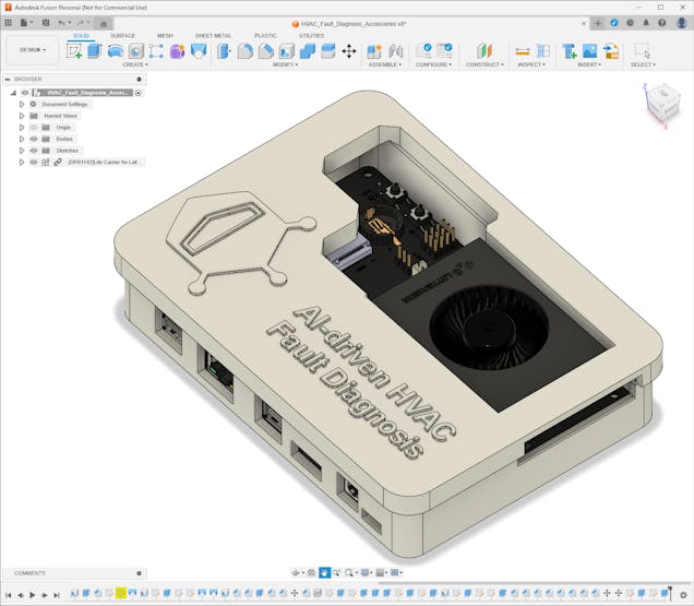
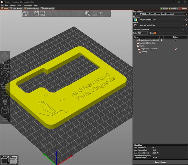
Furthermore, I decided to emboss the DFRobot logo and the project name on the top cover of the LattePanda Mu case to emphasize the qualifications of this segment of the AI-powered HVAC malfunction detection device.
I utilized Autodesk Fusion 360 to model all of the mentioned 3D-printable parts and test their clearances to print flawless joints. For further examination, you can download their STL files below.
![]()
![]()
![]()
![]()
![]()
![]()
![]()
![]()
![]()
![]()
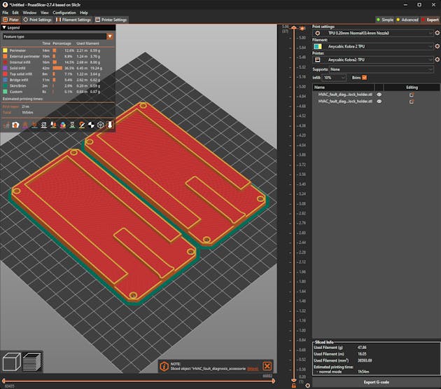
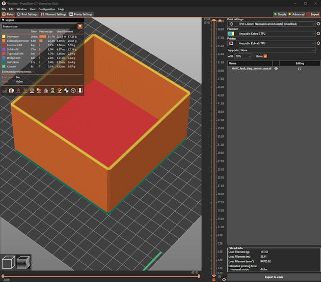
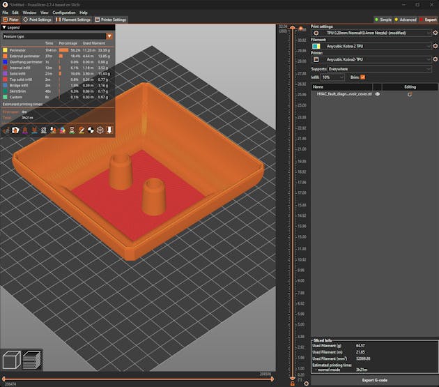
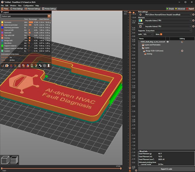
After designing 3D models and exporting them as STL files, I sliced the exported models in PrusaSlicer, which provides lots of groundbreaking features such as paint-on supports and height range modifiers.
![]()
![]()
![]()
![]()
![]()
![]()
![]()
![]()
![]()
![]()
Since I wanted to print pliable parts unsusceptible to water pressure and enclosing the Lite Carrier board perfectly, I utilized this TPU (flexible) filament:
- eTPU-95A Color Change by Temp
Thanks to this TPU filament's temperature-based color-changing ability, I was able to observe the current water temperature effortlessly while simulating thermal cooling malfunctions.
Finally, I printed all of the mentioned models with my Anycubic Kobra 2 3D Printer.
![]()
AI-driven Sound and Thermal HVAC Fault Diagnosis
Identify the faulty components via anomalous sound detection and diagnose ensuing cooling malfunctions via thermal visual anomaly detection.


Discussions
Become a Hackaday.io Member
Create an account to leave a comment. Already have an account? Log In.