Shoaib Mustafa
-
Did spectroscopy!
08/10/2024 at 07:12 • 0 commentsFound the reason why my eyes were straining. will explain after i explain the spectroscopy.
Since my project revolves around changing and understanding CIE coordinates of colors and converting those values to appropriate pwm signal for the lasers to result in a desired color, i had to find the exact wavelengths of lasers that i was using in order to get a gamut (region of colour space with all the colours available).
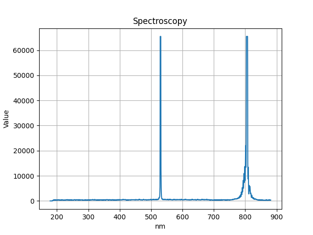
For this i used a USB2000+ spectrometer from Ocean optics. a spectrometer basically tells you where the incident light lies on the wavelength scale and what the intensity or saturation is. I first tested with green laser. It was being problematic at first and showing multiple peaks which made us conclude that the laser needs to be exactly pointing to the slit, a slight deviation would result in multiple peaks. but even after adjusting it a multiple times we couldn't get rid of an IR peak at around 800nm which shouldn't be there.. it wasn't there with other lights.. just with this laser. It seems that the peak needs not be clipped for an accurate measurement, instead it needs to be smooth with no sharp edges. this can be fixed by reducing the intensity of the laser. i put an optical diffuser (sort of a lens that dims down light) in between the path of light and reduced the duty cycle of the laser to a value of 30 to get good results. So i got the following result from data captured with the spectrometer.
![]()
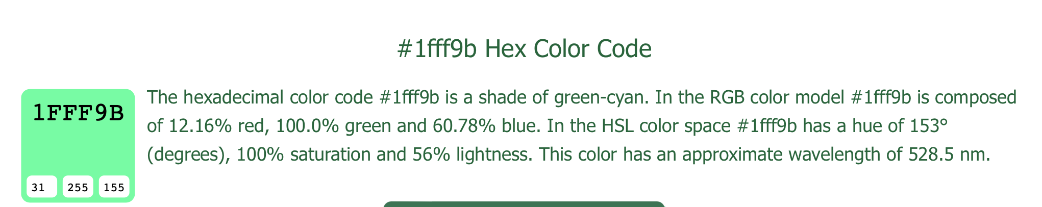
We can ignore the rest and focus on the fact that at 528.455nm it was showing the highest saturation. Checking that it indeed was giving the write results i searched and it is indeed.
![]()
setting the usb2000+ inline with the beam was hard, the optical table did not have holes where i wanted them.. so i used a railing to put everything on it inline.. i then only had to change the vertical axis to bring it inline with the beam. I wonder now whether light transmission was supposed to be done with an appropriate fiber optic cable? I checked in the lab we had a fiber optic but no way to align the lasers small beam to fiber's small core. I wish i had sort of a collector for the light like a funnel.
Next i have to find a way to generate PWM signal of the three lasers combined to result in a specific CIE coordinate. of course i'll start with one colour first. say different shades of green will have different CIE coordinates and that can be achieved with pwm duty cycle? i'm not sure gotta check.
-
Testing PWM with green laser
08/09/2024 at 21:54 • 2 commentsI tested the PWM with a green laser using a 2N2222 transistor between it and the microcontroller. At 1 kHz, the laser did not turn on, but it did at higher frequencies. When I tested it at 10 kHz, it worked, so I guess my theory that frequency wouldn't make a difference was wrong. I wonder if a MOSFET would behave differently—I'll give it a try.
Green Laser:
- The power supply to the laser is set at 6V with a maximum of 400mA.
- The laser draws 350mA at 100% duty cycle.
- The laser barely turns on at an ARR value of 13, but it steadily turns on with a dim beam at an ARR of 15 (or 15% duty cycle). I still need to determine the minimum value required to turn it on and then offset all future PWM signals accordingly.
For further testing, I need an easier way to control the PWM signal. Right now, I'm re-uploading the program repeatedly with different values. I think using a potentiometer to map to the ARR value might work.
P.S.: Although this laser is common and weak, I still feel my eyes straining when working near it. It seems that 6V at 350mA equals 2W, which is not exactly common. Never mind—I found some glasses and will wear them from now on. Haha!
A Question: Can I set the CCR to a value between 0 and 100 to correspond to the duty cycle?
No, the CCR can be set from 0 to the value of ARR. In the case of an ARR value of 1000, CCR can range from 0 to 1000. The CCR is used to control the duty cycle, and this value is compared with the ARR value to generate a certain duty cycle DD.
-
Getting the PWM to work for laser control.
08/09/2024 at 21:51 • 0 comments
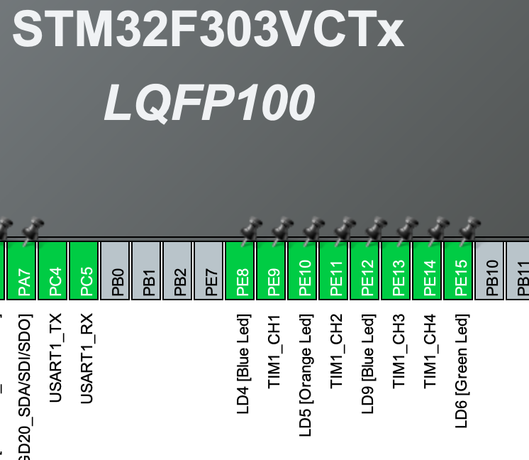
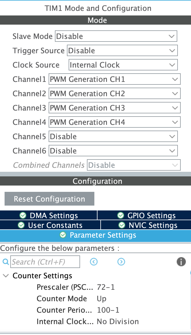
The pins essentially serve as output points, with the main operation driven by the clock. I first identified which timer each pin was associated with. In this case, the pins are linked to Timer 1, specifically channels 1, 2, and 3. I enabled them one by one, setting the clock source to internal since my board doesn't have an external source. I then configured the settings, paying close attention to the prescaler and period values, which determine the frequency. The frequency can be calculated using the following equation:For my setup, the APB1 clock speed was 72 MHz. So, the frequency was:
If a 1 kHz signal is desired, only the period needs to be adjusted. The equation then becomes:
For 1 kHz:
Period = 999
I confirmed with an oscilloscope that the frequency was indeed correct.
I then switched to the STM32 to take advantage of its 16-bit PWM capability, which allows for values between 0 and 65535. However, I'm not yet certain if it can generate a 1 kHz signal with 16-bit resolution—I'll need to investigate further.
The resolution can be calculated with the formula:
For a period of 999:
This is approximately 10 bits, offering 1024 discrete steps, which is better than the 8-bit resolution with 256 steps. However, I'm curious if it's possible to achieve 16-bit resolution while maintaining the same frequency. My question is: why should the signal frequency matter when we're only concerned with the duty cycle?
The pins were selected as follows:
![]()
The setting of the PWM channel was done as:
![]()
-
Introduction and STM32 Timers
08/09/2024 at 21:40 • 0 comments![]()
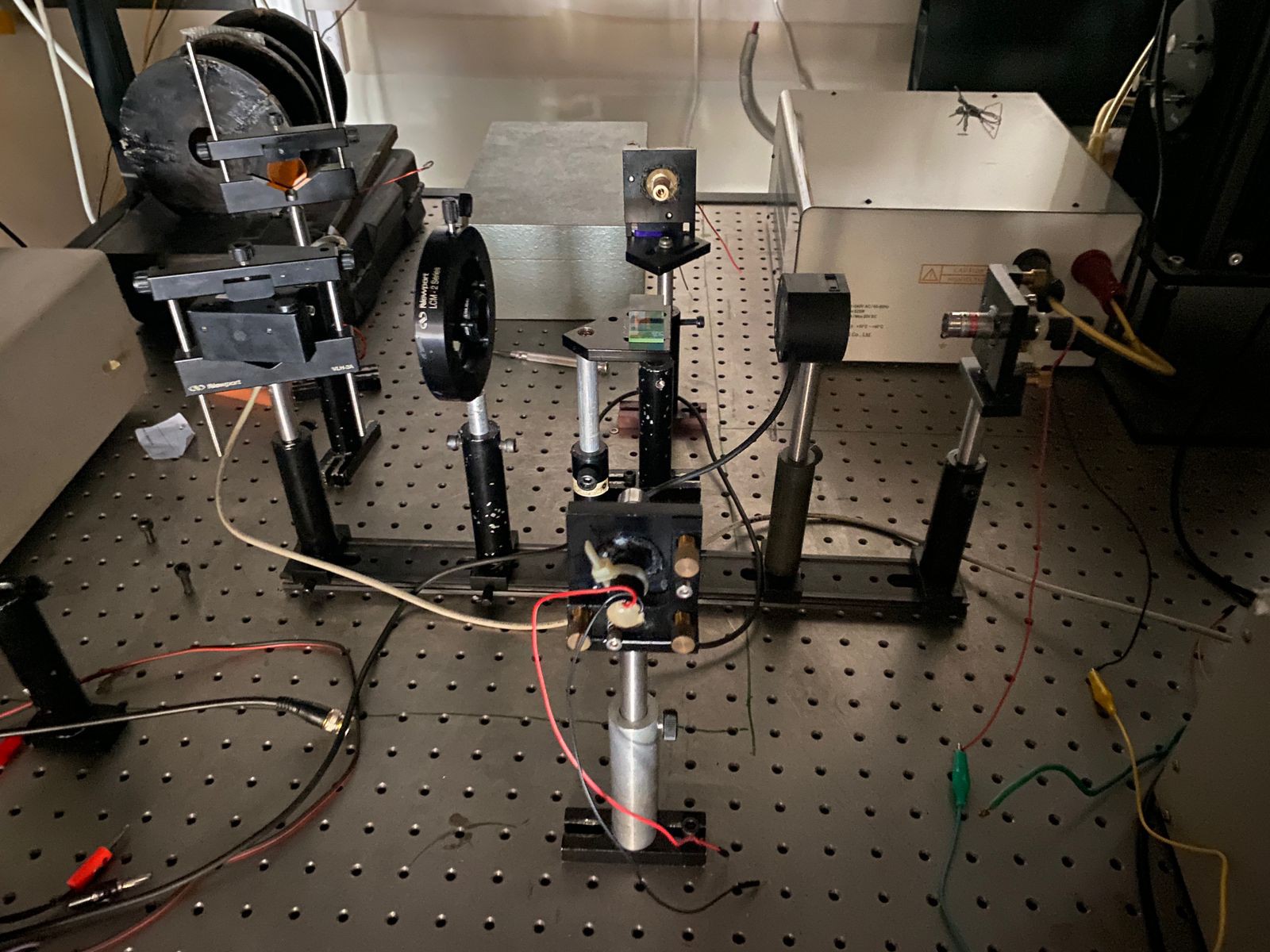
My setup
![]()
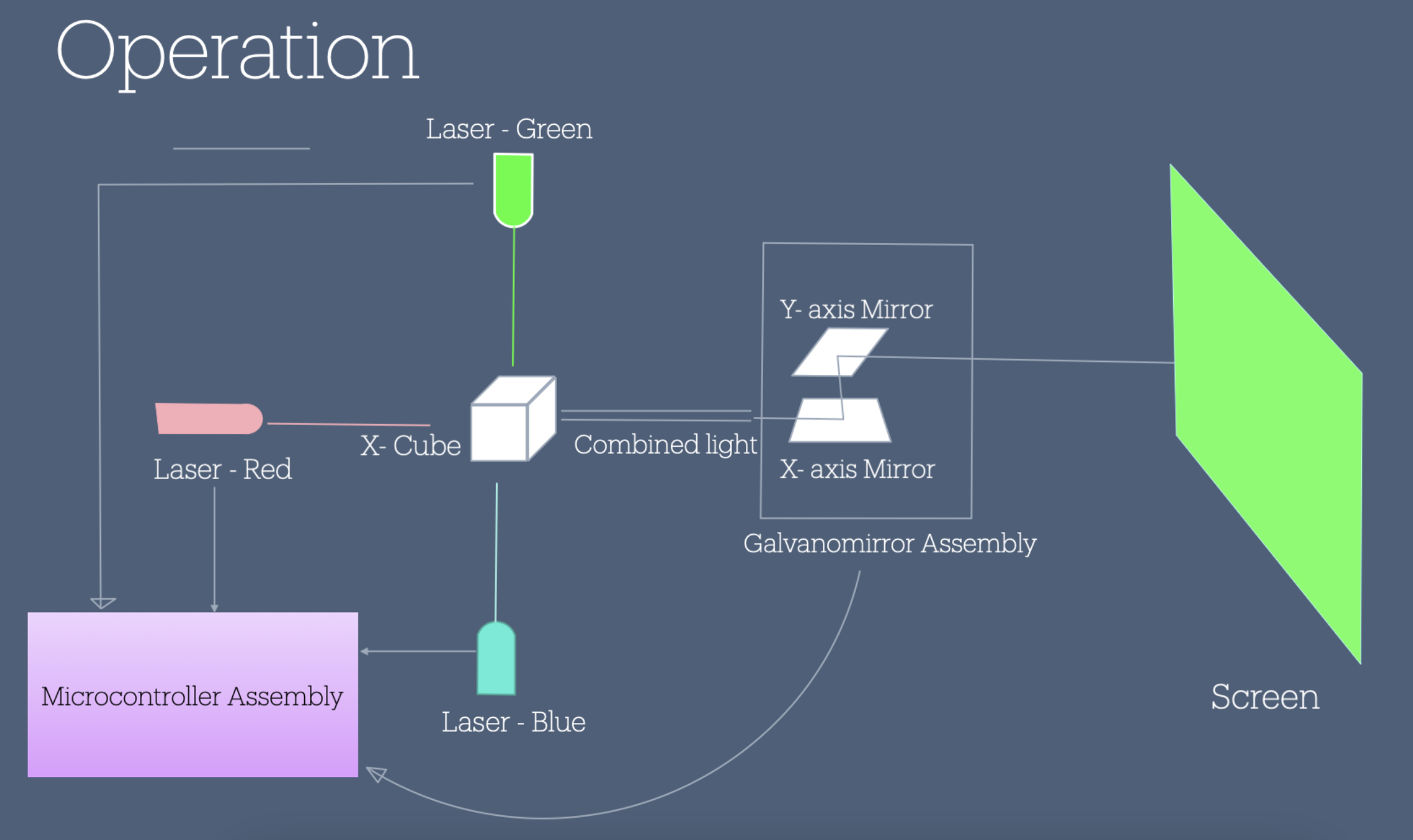
The plan of action is the following, Get the hardware working to control the power of the lasers, get the galvo working with DAC and appropriate circuitry to project the laser onto a screen. write software that will take care of projection and decoding and encoding images.
Hardware Setup
I realise PWM works a bit differently than with Arduino mainly because of the abstraction. so i'm looking into making it work with STM.
NOTES STM Timer module
Timer module in be in several different types
1- Timer mode TCNT register gets incremented by 1 after every clock cycle. the oscillating source goes through prescaler and then increments after every clock cycle. this mode can give an overflow interrupt when register is full. usually at 80Mhz and 1:1024 prescaler it's 0.89seconds. but if we want the interrupt to occure every 1 second.. we can use the preloader to not start the count from 0 but from some other value.
2- Counter mode Instead of clock source can take any input and at rising or falling edge of signal the TCNT register increments by one. note that in this mode it also goes through the prescaler so we can set that to 1:1 to get real value
3- General timer module all timer module consists of counter register, Auto-reload register with a preload register access and prescaler register.
PWM Mode of timer module In PWM mode, the timer module is clocked from an internal clock source and produces a digital waveform on the output channel pin called the PWM signal. By using output compare registers (OCR), the incrementing timer’s register value is constantly compared against this OCR register. When a match occurs the output pin state is flipped until the end of the period and the whole process is repeated.
The timer in PWM mode will produce a PWM signal at the specified frequency the user chose. The duty cycle is also programmatically controlled by its register. The PWM resolution is affected by the desired FPWM and other factors as we’ll see in the dedicated tutorials for PWM generation.
I'll be following "Discovering the STM32 Microcontroller" by Geoffrey Brown to get a better understanding of this controller.. too many concepts are flying right over my head as of right now.
Laser Projector
Laser projector with 3 lasers (RGB) incident on an x-cube(dichroic) with galvanomirror