-
Redo
11/16/2017 at 22:07 • 0 comments![]()
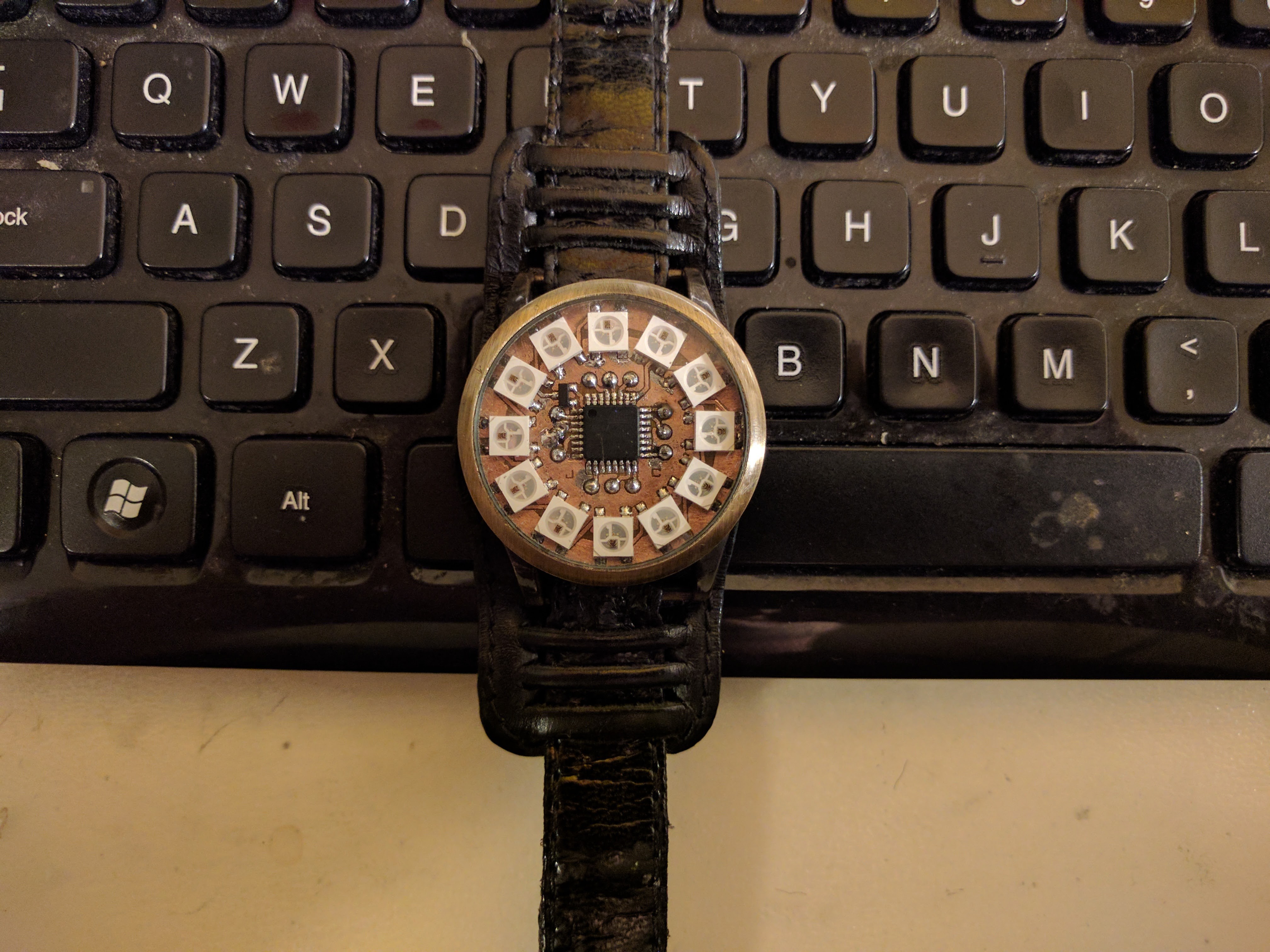
The first day of the semester, in disconnecting the battery for charging, my hand slipped and cracked the pcb severing a number of key traces under a few components. I am remanufacturing the pcb and as part of a school project, rewriting the code to be c++ outside the arduino environment. As part of remaking the board, i've made a few traces bigger and also increased the clearence to make pcb etching a little more reliable for this design. Pics of the assembly as well as sourcecode will be uploaded next week. stay tuned.
-
Programming and testing
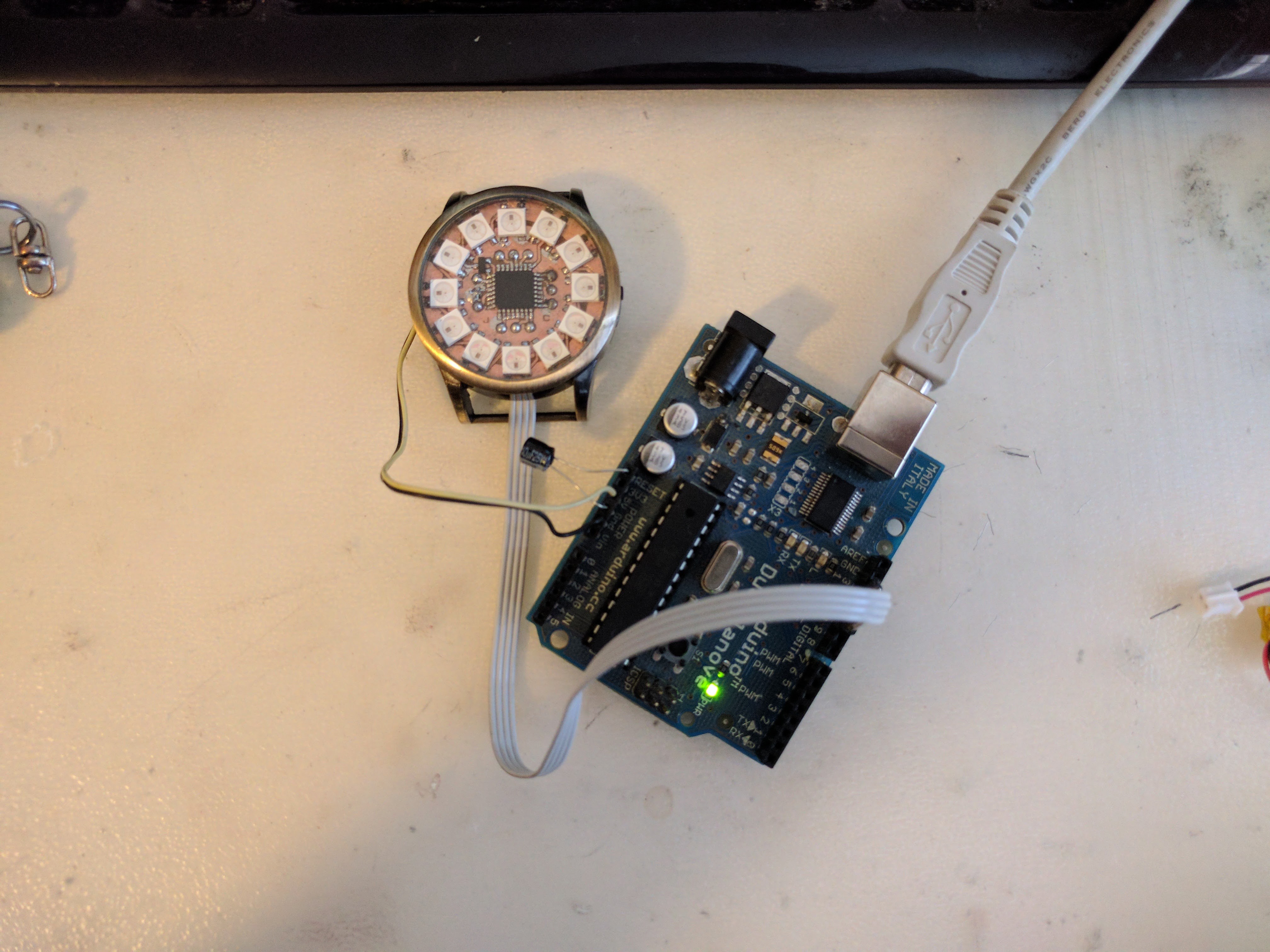
07/25/2017 at 16:43 • 0 commentsFor this step, i used an arduino dumilanove as a programmer.
![]()
I'll post my code later, as right now it's ugly. I did program this in the arduino environment, but only because i'm lazy. Be sure to burn the proper fuses first. Arduino set the brown out detection at around 4 volts by default. Obviously this will keep your system from working at 3.7-2.9V, that and the BOD drains around 4mA all the time, so you're going to want it completely disabled.
I recommend MCUdude's minicore. In arduino preferences, add https://mcudude.github.io/MiniCore/package_MCUdude_MiniCore_index.json to your board manager URLs and install minicore from the board manager.
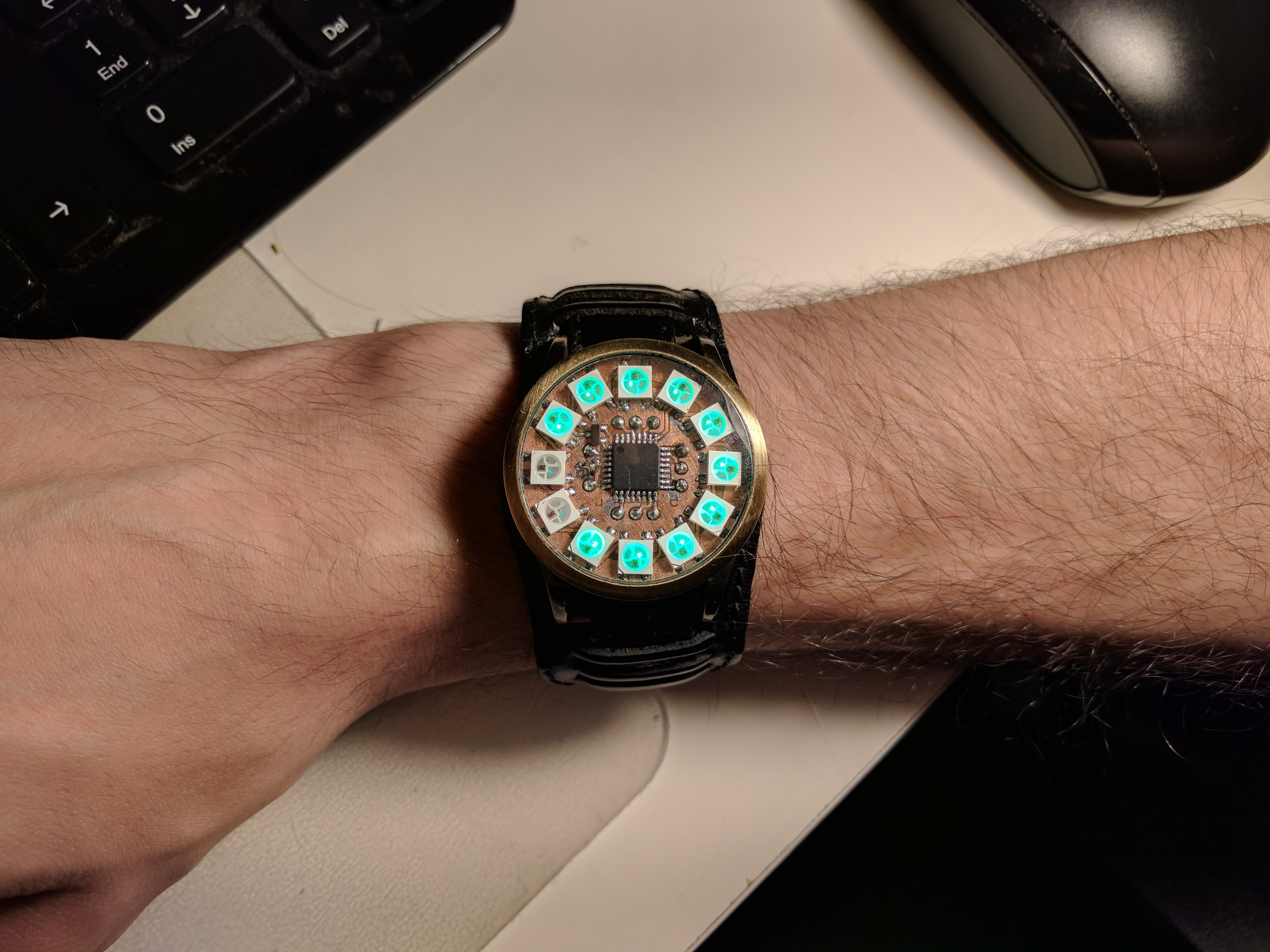
His excellent work will allow you to change individual fuse settings very easily. For this, select atmega328, 8mhz internal clock, 328p variant, and BOD disabled. burn the bootloader and then you can program it however you want. You'll probably want a ws2812 and ds1302 library. Don't forget to keep your AVR asleep when not in use, my whole system uses about 40 micro Amps when asleep, and around 90mA when showing the time. If it was awake all the time, my 110mAh battery would last only an hour at best.
![]()
![]()
-
Etching
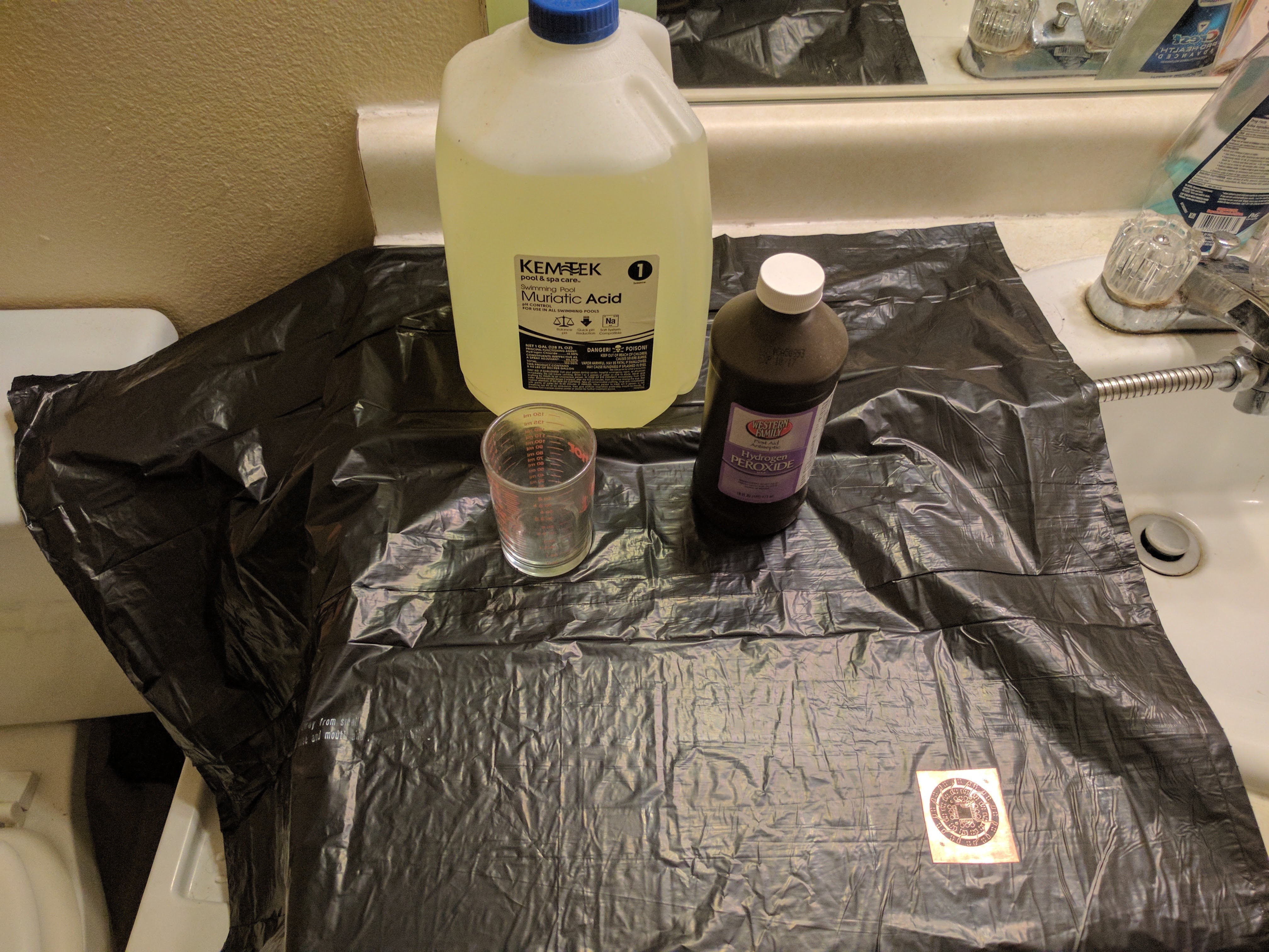
07/25/2017 at 16:24 • 0 commentsFor this, you will need first and foremost a clean, open space to work, with easy access to running water. Since i had neither clean, nor open space, i settled for the bathroom.
![]()
Shown is everything needed to etch a board successfully. I used the small beaker to use little acid. My muriatic acid is only 14%, so I used a 50/50 mix of hydrogen peroxide and acid. ALWAYS add the hydrogen peroxide FIRST, then add the acid! Do this in a well ventilated area as it may fizz a little and you do not want to inhale it.
![]()
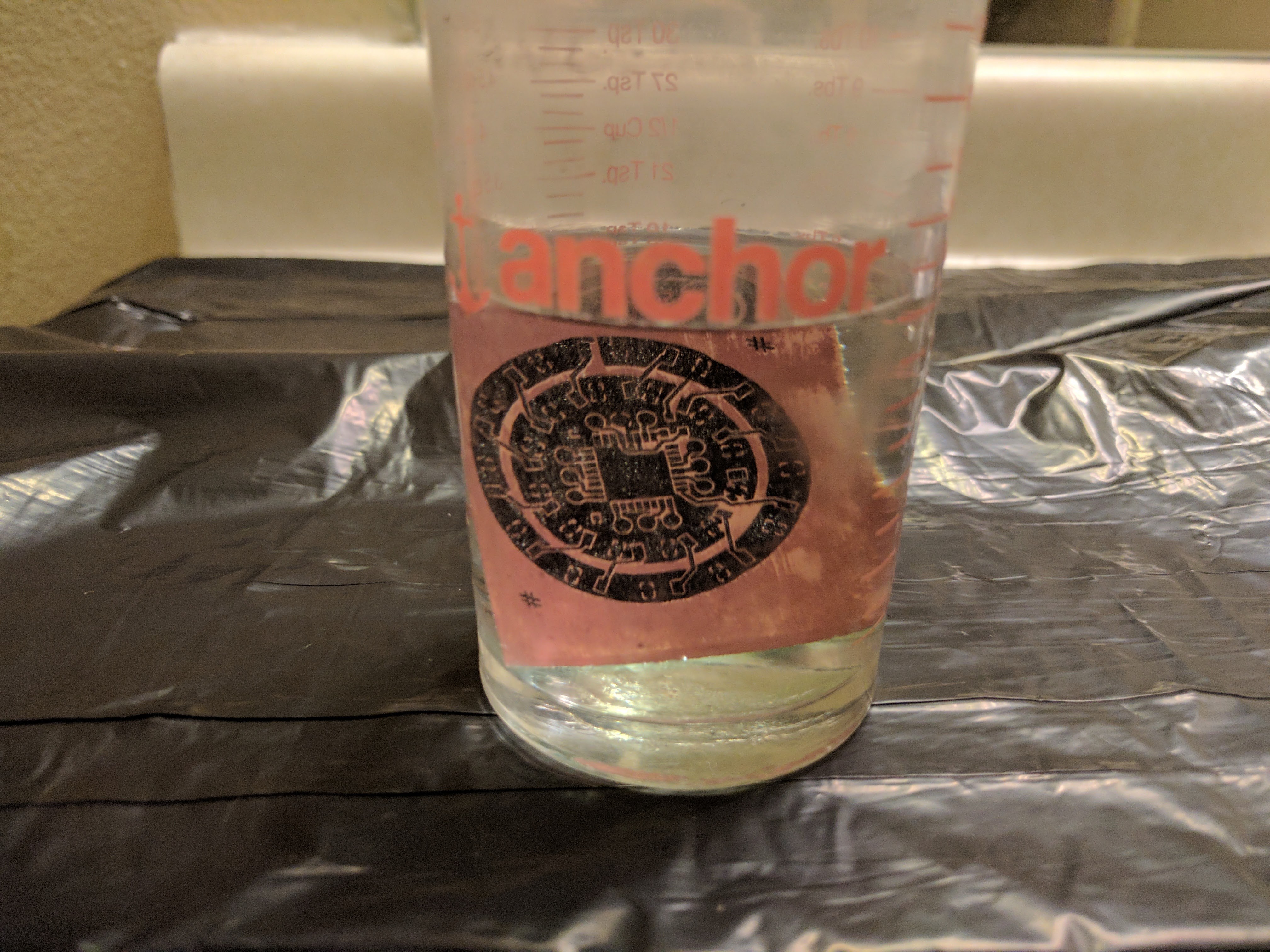
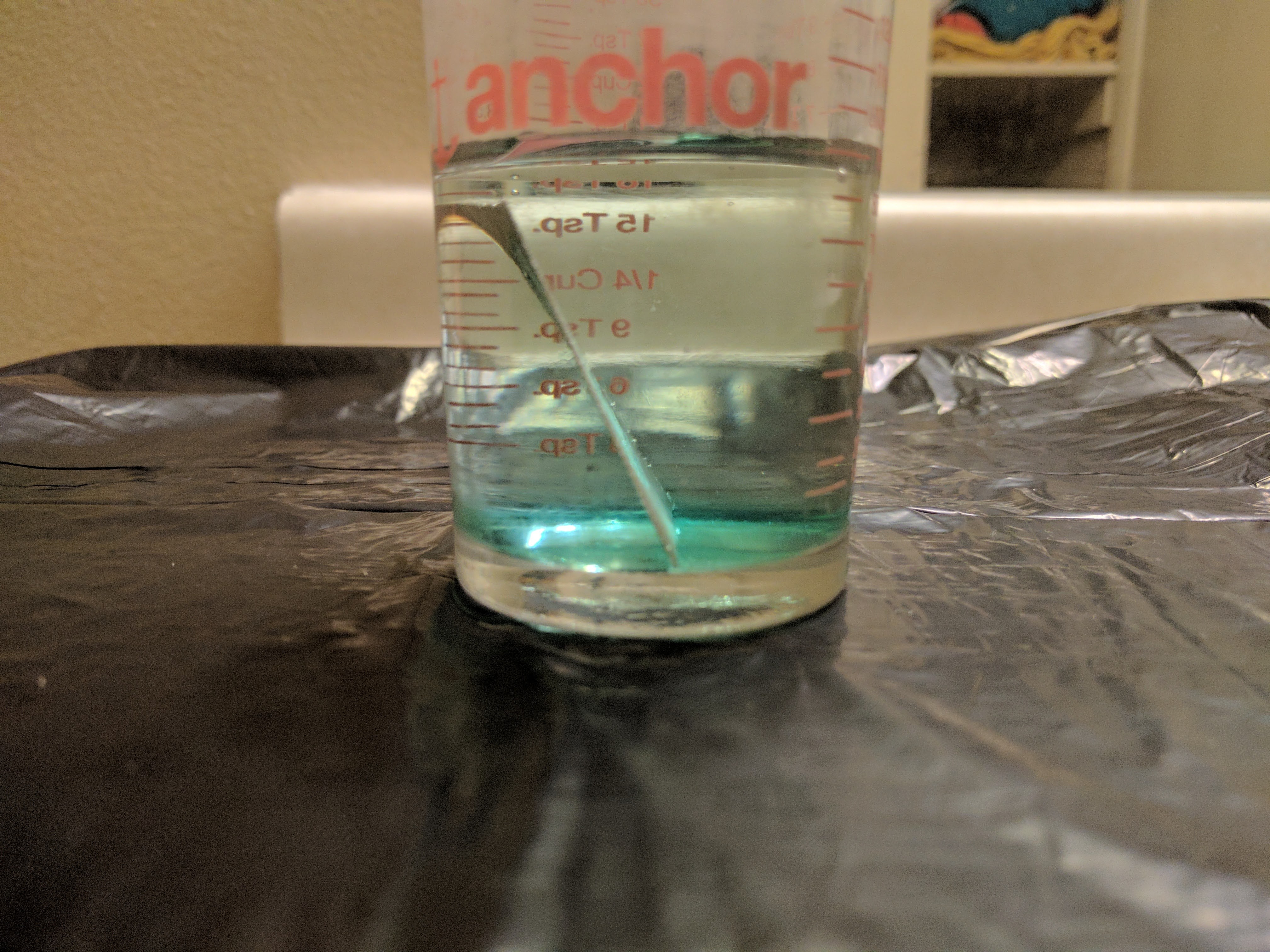
Use the smallest amount of chemical you can. The amount in the beaker is pretty much ideal. This photo was taken immediately after adding the board and you can already see a faint green hue at the bottom, that is the copper oxidizing and dissolving in the acid.
![]()
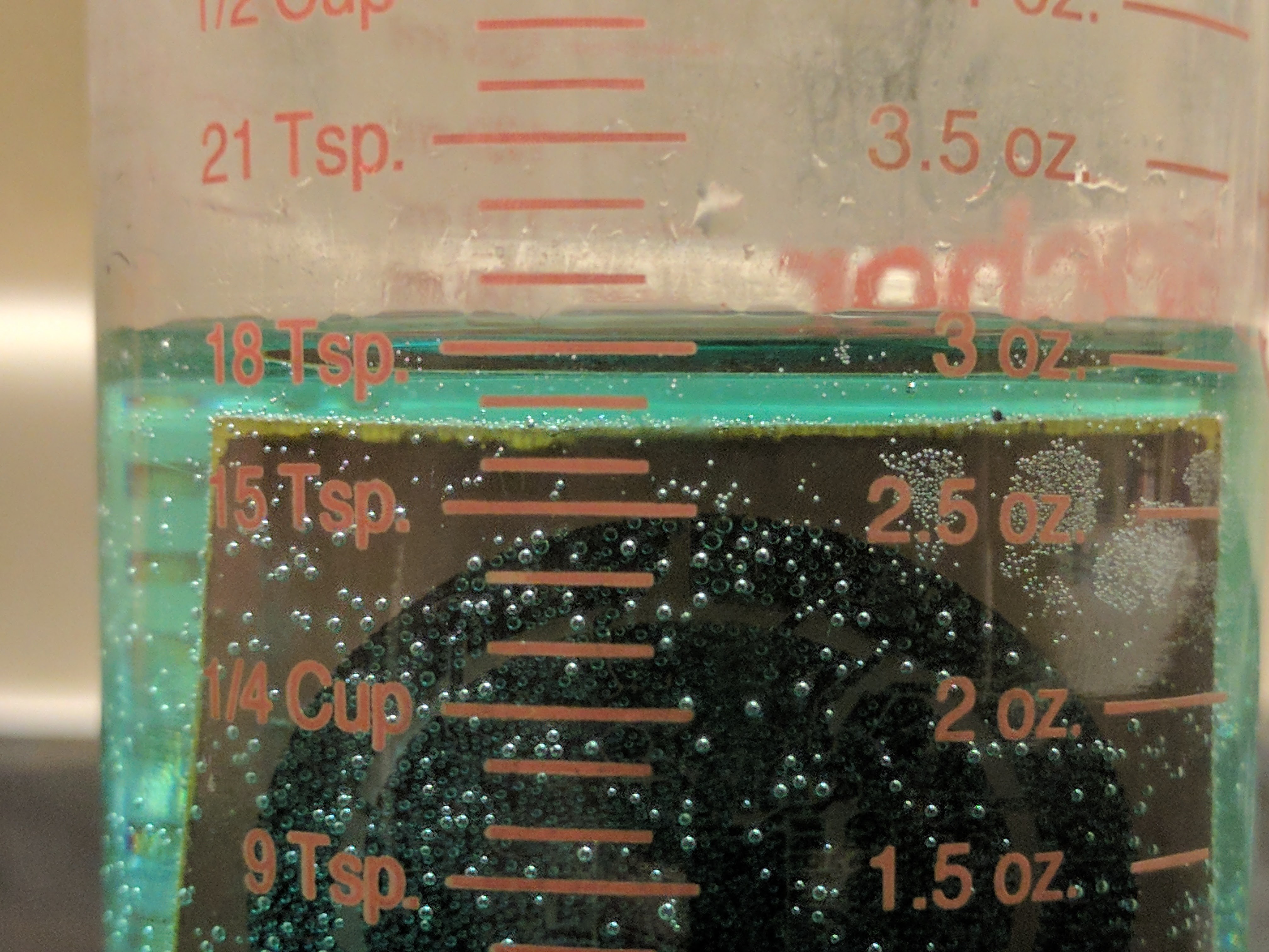
This was taken about 30 seconds in. If your mix is good, it will work fast.
![]()
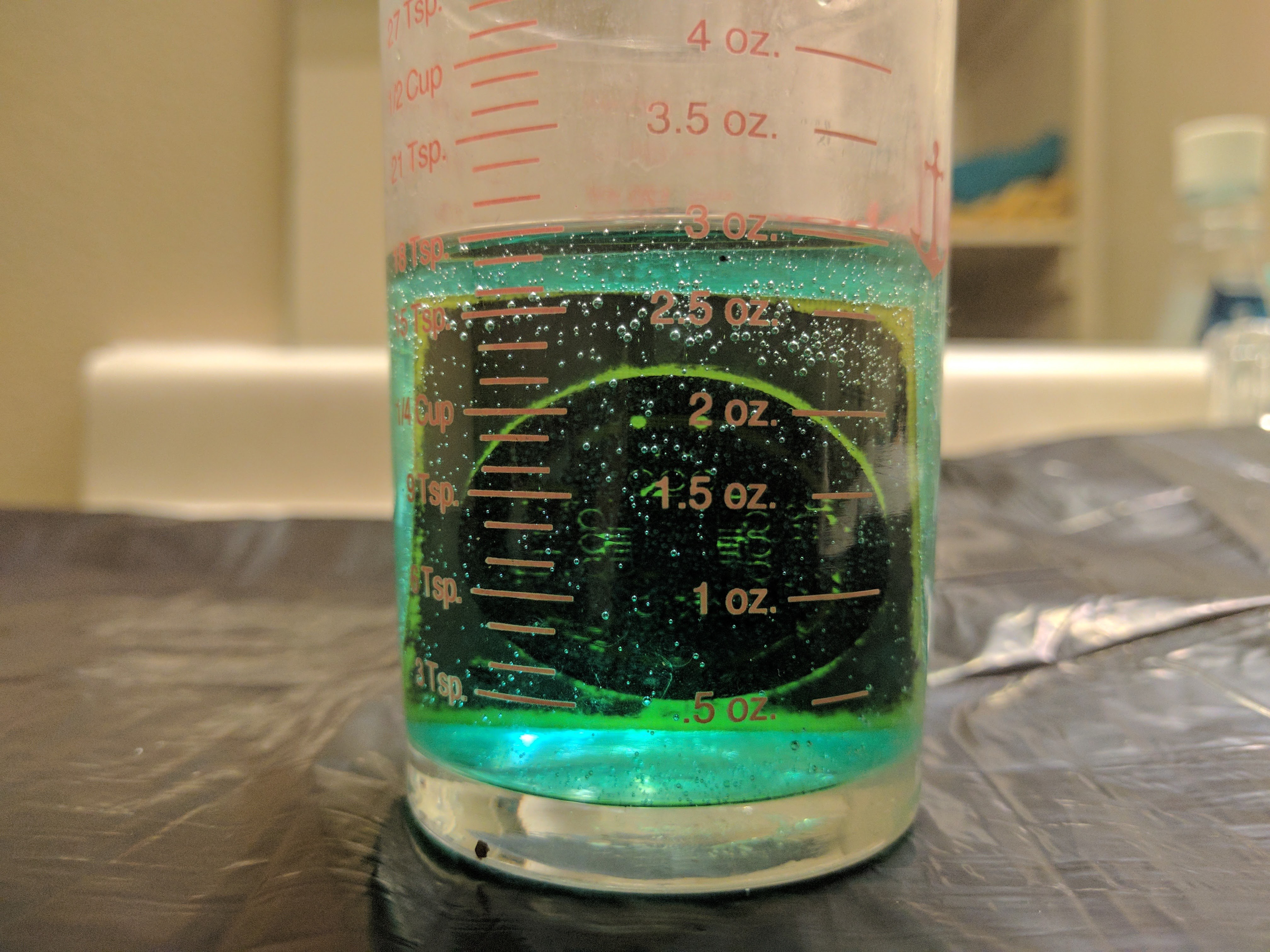
At about two minutes you may see the edges eaten through first. My board has a really thin layer of copper, so your milage may vary.
![]()
After your board is completely etched, remove it from the acid and rinse with water for a few minutes. While it's rinsing, examine it carefully to make sure there are no obvious shorts. Sometimes, it may be easier to use an engraving tool to fix shorts and to try and add jumper wires where too much was copper was removed. After visual inspection, use a multimeter to find shorts. The multimeter will find any shorts your eyes miss, and this board had a few.
I was a little excited to build this so i didn't take pictures during soldering, but sparkfun has a terrific tutorial on soldering small packages.
-
Almost good enough
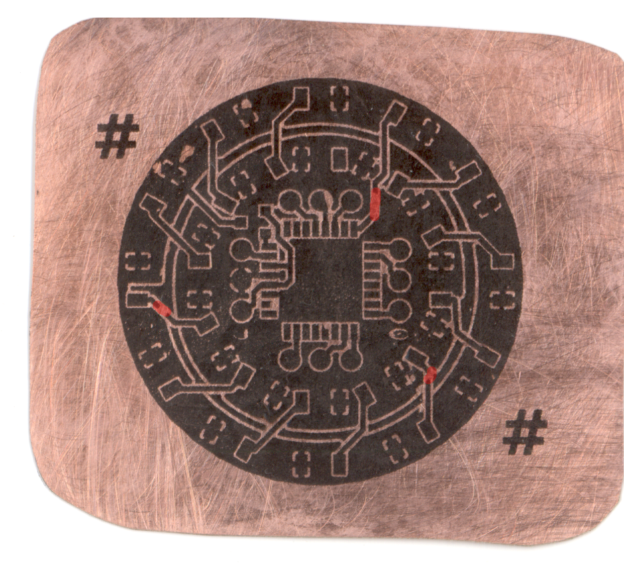
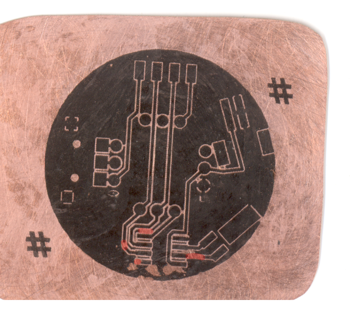
02/13/2017 at 23:15 • 0 commentsI just finished my first attempt (for this project) at a toner transfer. I always inspect my boards with my flatbed scanner. I highlighted the unacceptable problems in red.
![]()
![]()
As you can see, the errors are small, but in critical spots. This board is a little too small for a sharpie touch-up, larger boards are way more forgiving. Next step, clean the board and try again.
Once i complete this step satisfactorily, i'll reveal my secret sauce in the instructions.
-
Design
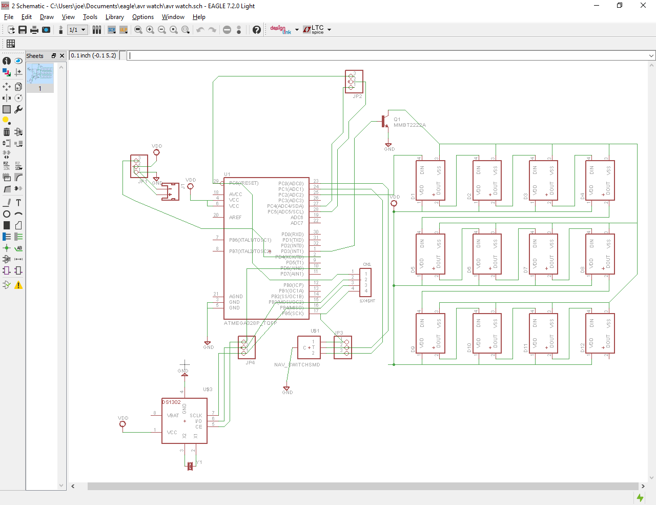
02/06/2017 at 05:59 • 0 commentsMy eagle schematic is a bit sloppy, but I hope it is clear enough to understand the general idea. I'm using the ever popular atmega328p in a less popular tqfp package for the microcontroller, the slightly esoteric ds1302 for timekeeping and the wildly popular ws2812 led for readout.
![]()
![]()
This step was a lesson in eagle-fu for me, as I learned how to use a few handy scripts and techniques. Chiefly, the cmd-draw.uld script for creating the circular pattern of led's, and the witchcraft that are ground planes. Sparkfun's tutorials are an excellent resource for learning these. That is, if you wish to continue an unhealthy addiction to a product with inflating prices.
I also followed sparkfun's tutorial on making new part packages, as my choice of RTC had no surface mount eagle part. If you'd like to cheat, you'll find the library I made attached.
Next, I'll show you how I prepared my design for printing and toner transfer... After my homework is finished.

