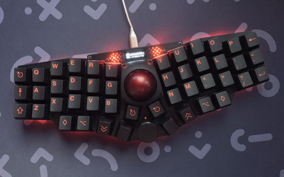
So I had spent some time looking at my input device options and determined that trying to reverse-engineer the WK-50 was still the best strategy forward; I skimmed through the trackball section of KBD and community boards really aren't that far off from the WK-50 that exists right here and now, usability-wise. I'm looking again now and the WK-50 looks an awful lot like Cocot46plus:
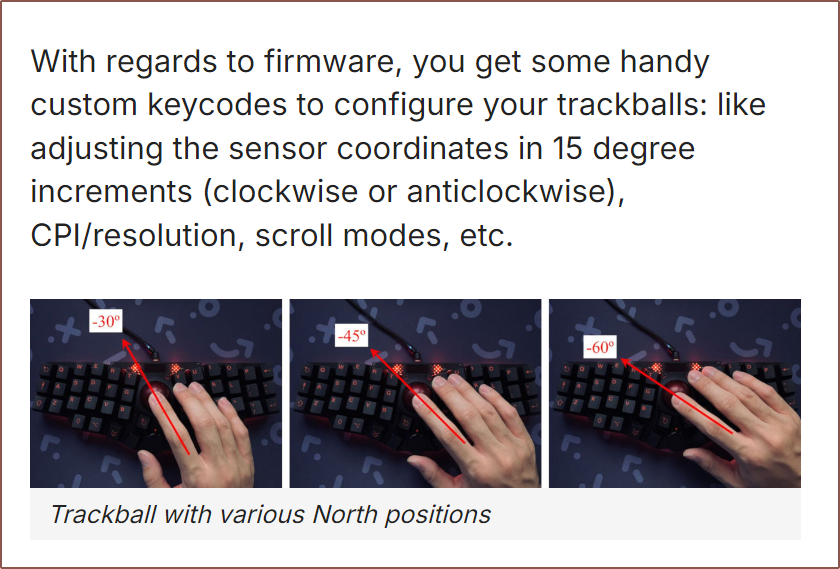
It even has that angle realignment feature I thought was a bug:
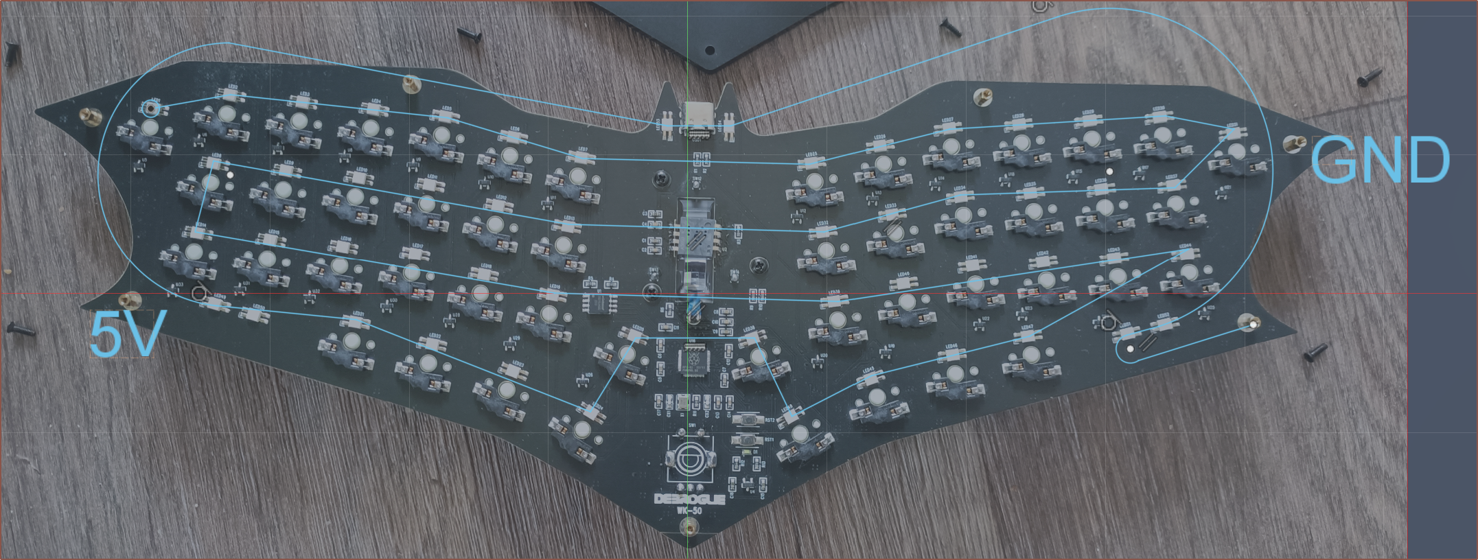
ARGB Order:
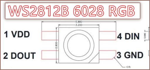
After determining that the LEDs are probably "Reverse Mount 6028 SMD RGB LED WS2812B" and the VCC / GND agreeing with the 5V and GND pins on the USBC receptacle, I traced out the LED order with my multimeter in continuity test mode:
Matrix of transistors?
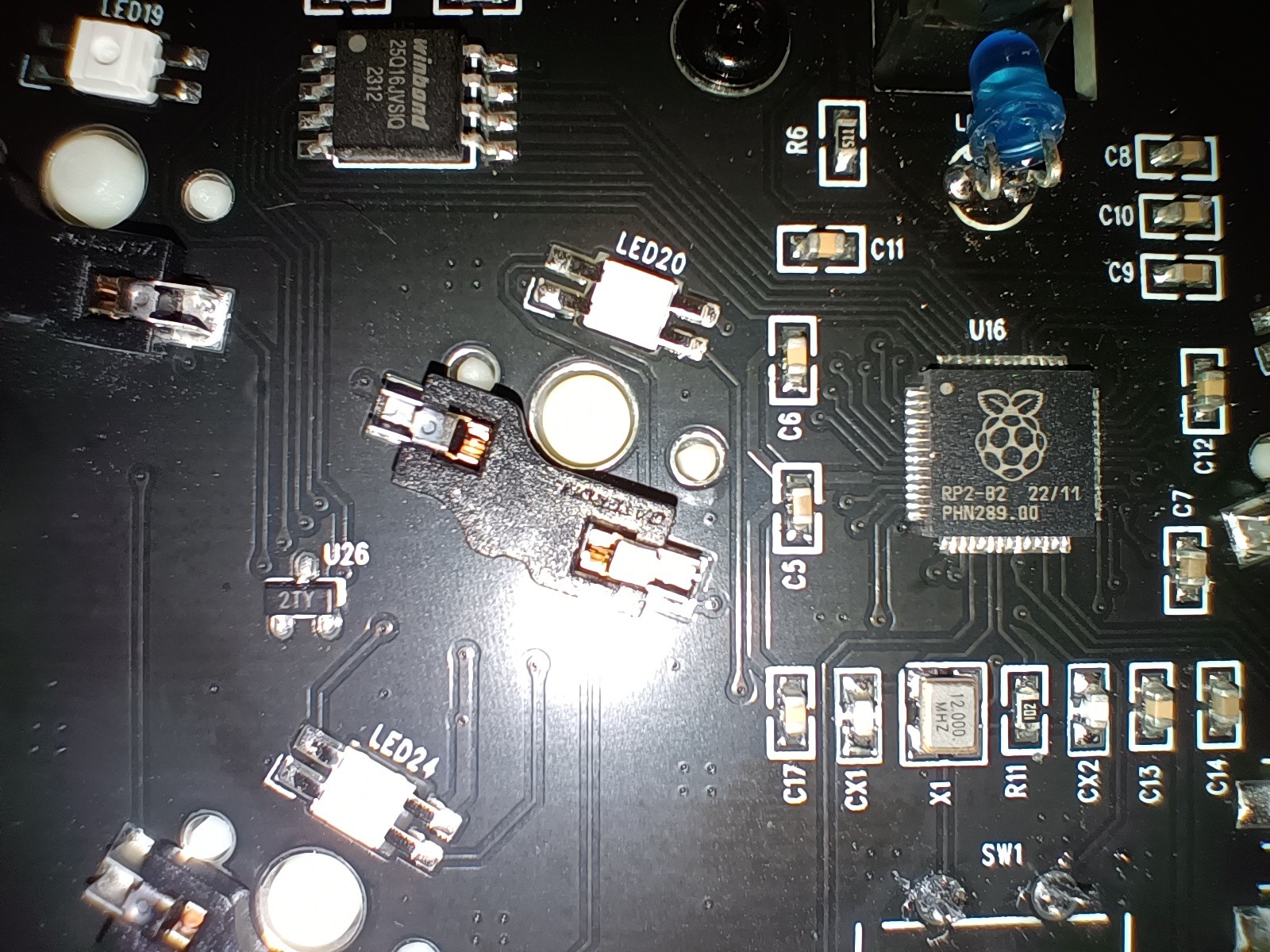
I was able to use macro camera on my phone to actually see the text on U4, which is the 3-pin black square south of the D1 LED. It's an SC662K, a 250mA LDO. All the other lookalikes are 2TY, otherwise known as the S8550 PNP transistor:
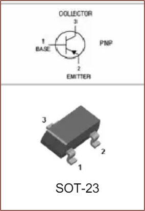
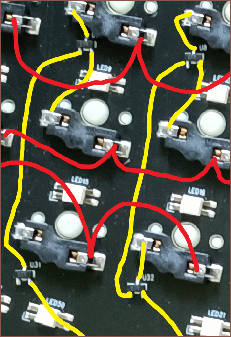
I've only heard / seen either direct-pin or diodes ever used for keyboard design. There's 2 transistors per column, and there are 4 rows. Perhaps it's to reduce the amount of passives required to place, thus lower costs and less things that can go wrong during manufacture.
The encoder push button is also on this matrix.
The misalignment of the ADNS-5050
I actually did the colums/rows pins last. First, I did more obvious ones to test to see if I could actually use my probes on the small RP2040 pins in the first place.
As it turns out, the manufacturer of the ADNS-5050 didn't actually align the pins for whatever reason. It seems that the board designer didn't notice this when making its footprint and that's the real reason why the sensor is 4 degrees off:
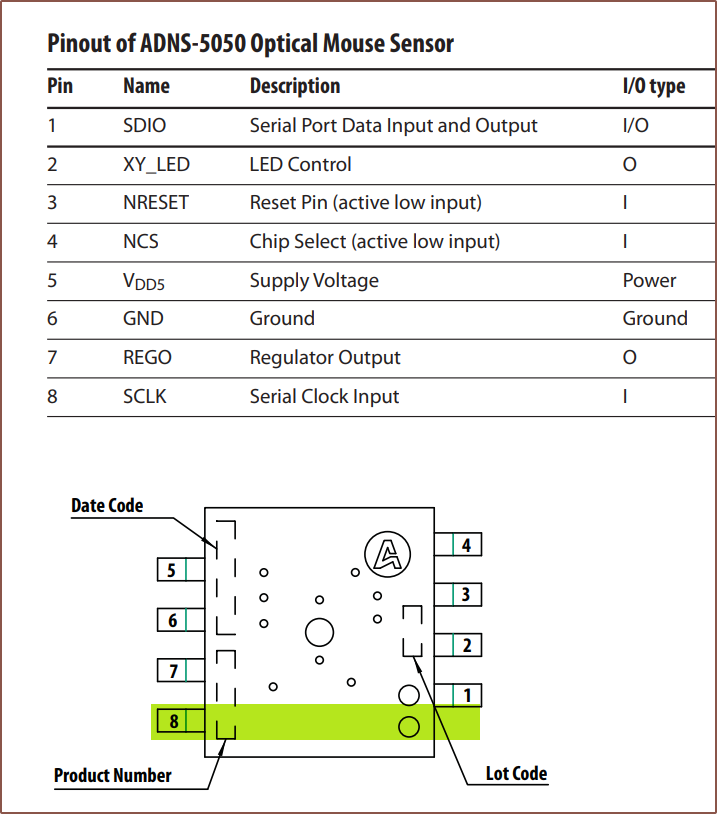 It's nice to know that the LED is actually controlled by the sensor. Also, I don't think NRESET is connected to the RP2040.
Discovered pinout
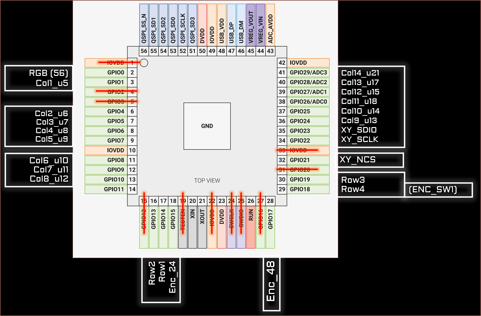 I've crossed off pins that don't visibly look connected to anything. I used them as a fiducial marker. The "_uXX" on the columns is the identifier for the topmost transistor on the column.
I haven't determined what GPIO11 nor transistor U26 connects to at the moment. At least it looks like there's a via right next to GPIO11. U26 actually doesn't look like it's connected at all.
 Enc_24/48 is the pin closest to LED24/48 respectively.
  kelvinA
Discussions
Become a Hackaday.io Member
Create an account to leave a comment. Already have an account? Log In.