-
1TEST SKETCH 01
![]()
![]()
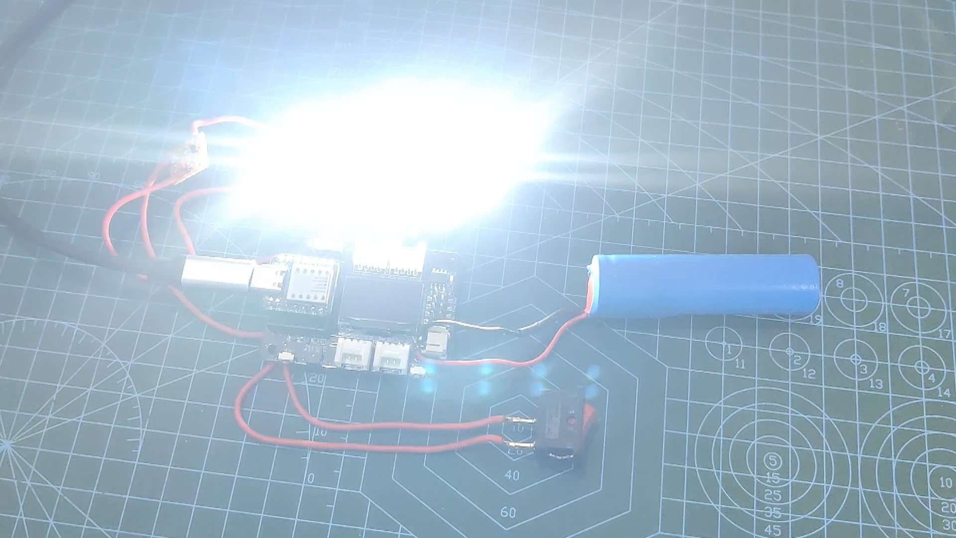
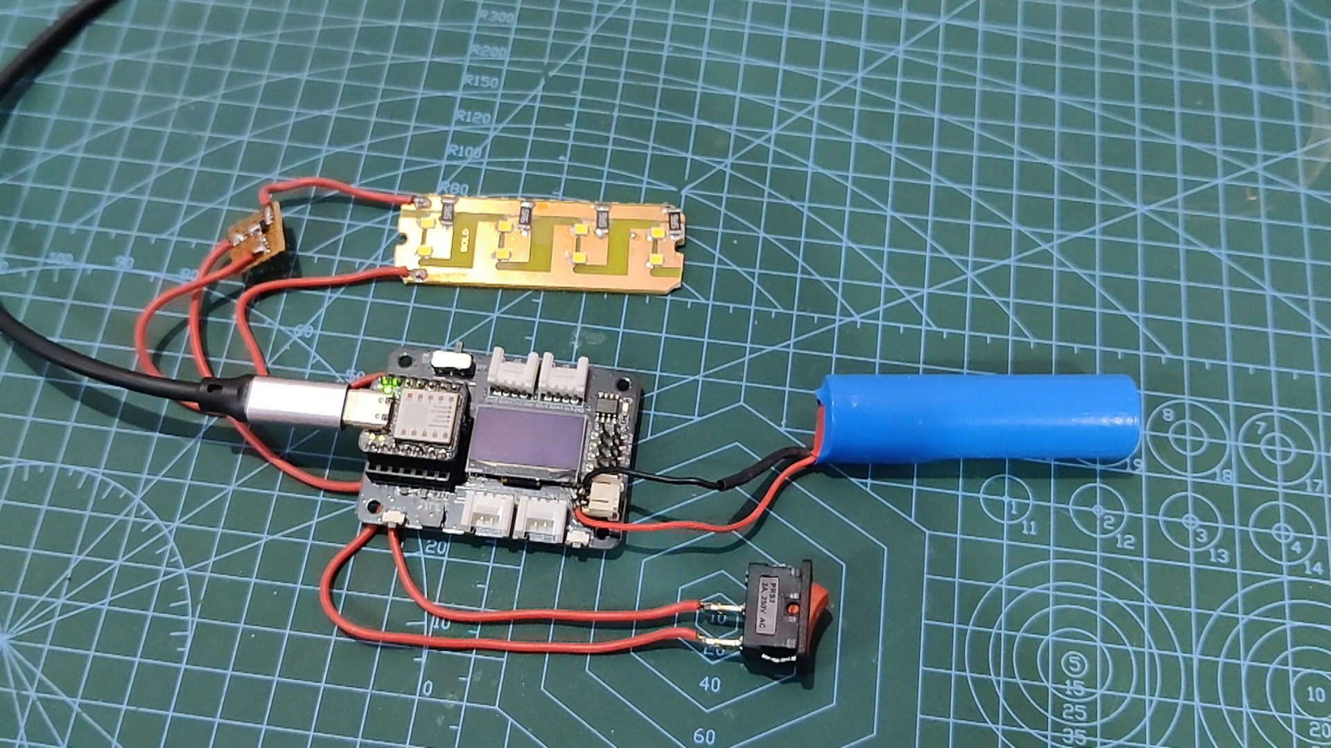
We added a basic blink sketch to the XIAO SAMD21 MCU in order to test this configuration. By passing the sketch via the microcontroller, LED Load turns ON and OFF, indicating that we are ready to continue on to the next stage, which is to add the main sketch to the board.
void setup() { // initialize digital pin LED_BUILTIN as an output. pinMode(2, OUTPUT); } // the loop function runs over and over again forever void loop() { digitalWrite(2, HIGH); // turn the LED on (HIGH is the voltage level) delay(1000); // wait for a second digitalWrite(2, LOW); // turn the LED off by making the voltage LOW delay(1000); // wait for a second } -
2TEST SKETCH 02
![]()
![]()
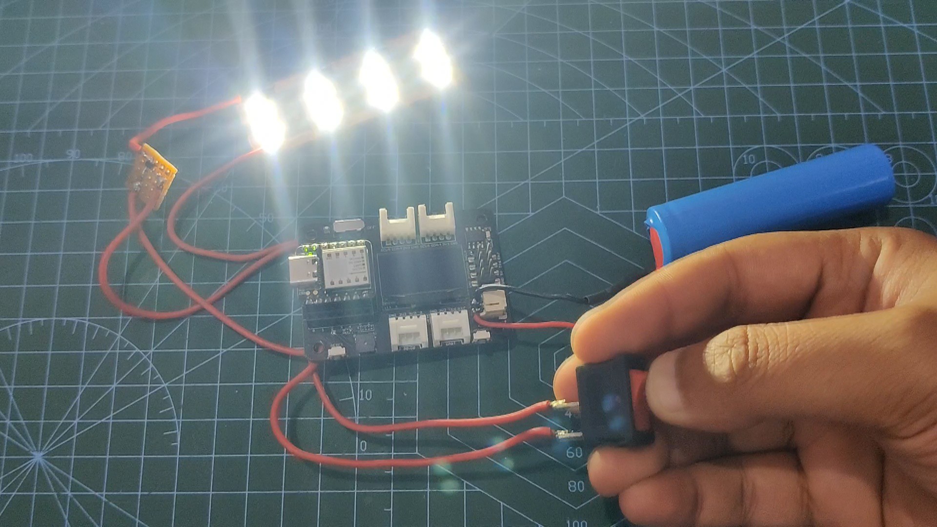
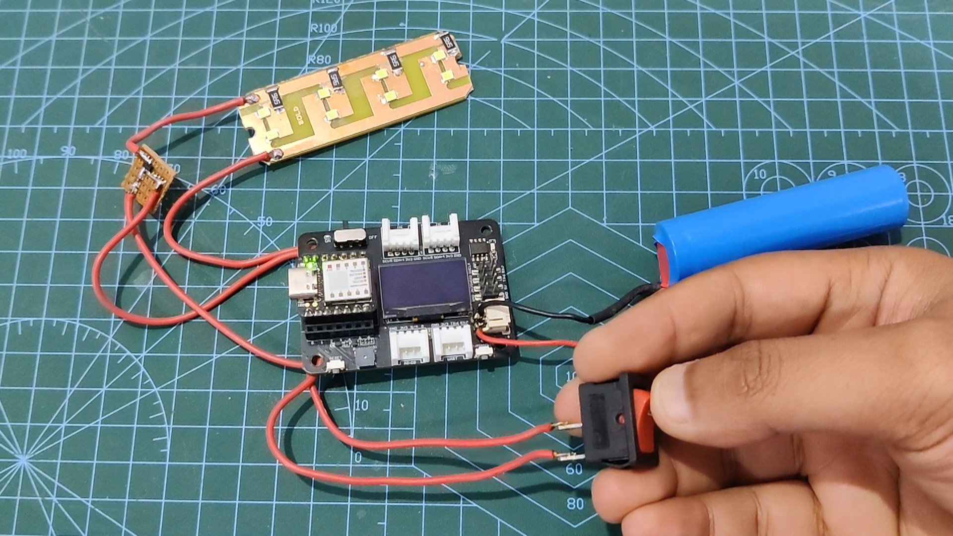
The main sketch was then uploaded into the XIAO SAMD21 configuration.
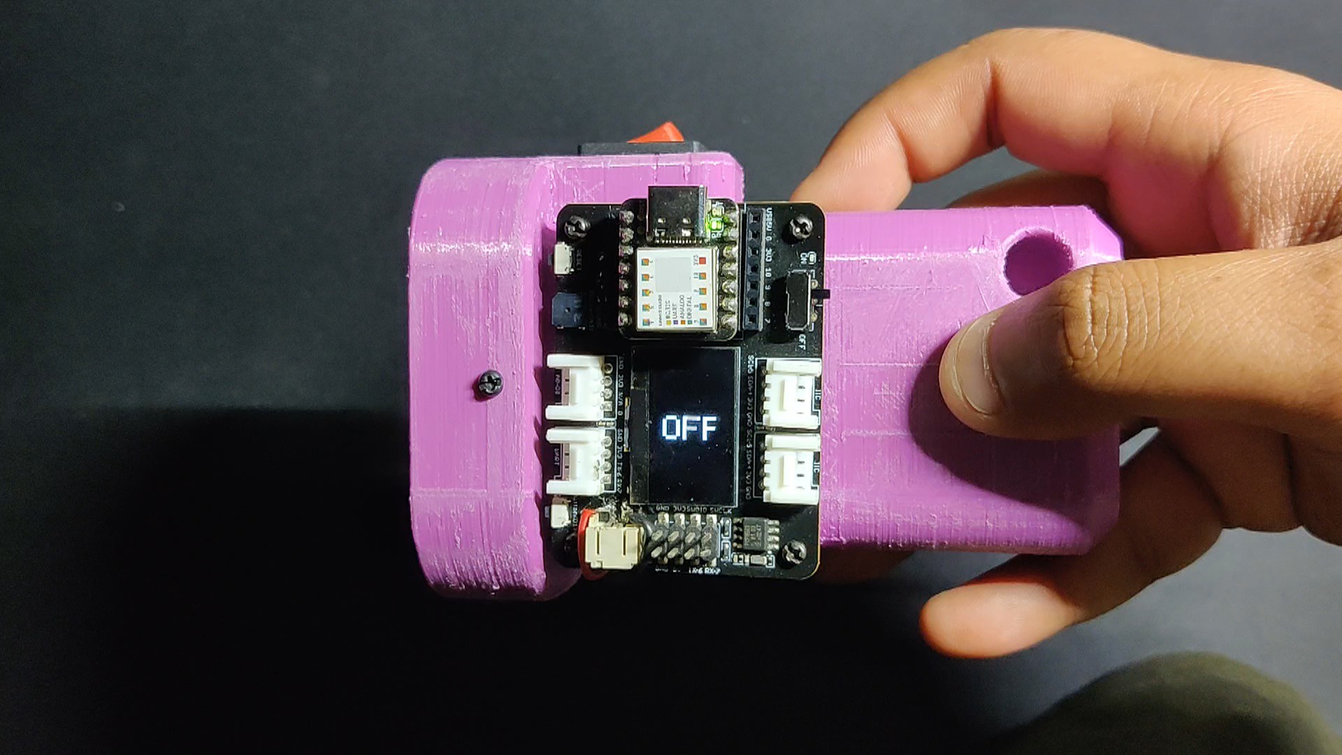
By pushing the switch, this code enables the user to toggle between various light brightness levels. An OLED screen, rotated to be viewed in portrait orientation, shows the brightness level currently in use.
#include <Wire.h>
#include <Adafruit_SSD1306.h>
#include <Adafruit_GFX.h>
#define OLED_WIDTH 128
#define OLED_HEIGHT 64
#define OLED_ADDR   0x3C
const int switchPin = 1;
const int lightPin = 2;
int lightMode = 1;
Adafruit_SSD1306 display(OLED_WIDTH, OLED_HEIGHT);
void setup()
{
pinMode(lightPin, OUTPUT);
pinMode(switchPin, INPUT_PULLUP);
digitalWrite(lightPin, LOW);
display.begin(SSD1306_SWITCHCAPVCC, OLED_ADDR);
display.clearDisplay();
}
void loop()
{
if (digitalRead(switchPin) ==LOW)
{
lightMode = lightMode + 1;
if (lightMode == 6)
{
lightMode = 1;
}
}
if (lightMode == 1)
{
digitalWrite(lightPin, LOW);
display.clearDisplay();
display.setRotation(3);
display.setTextSize(3);
display.setTextColor(WHITE);
display.setCursor(5, 55);
display.println("OFF");
display.display();
delay(500);
}
else if (lightMode == 2)
{
analogWrite(lightPin, 50);
display.clearDisplay();
display.setRotation(3);
display.setTextSize(3);
display.setTextColor(WHITE);
display.setCursor(5, 55);
display.println("20%");
display.display();
delay(500);
}
else if (lightMode == 3)
{
analogWrite(lightPin, 100);
display.clearDisplay();
display.setRotation(3);
display.setTextSize(3);
display.setTextColor(WHITE);
display.setCursor(5, 55);
display.println("40%");
display.display();
delay(500);
}
else if (lightMode == 4)
{
analogWrite(lightPin, 255);
display.clearDisplay();
display.setRotation(3);
display.setTextSize(2);
display.setTextColor(WHITE);
display.setCursor(5, 55);
display.println("100%");
display.display();
delay(500);
}
else if (lightMode == 5)
{
analogWrite(lightPin, LOW);
display.clearDisplay();
display.setRotation(3);
display.setTextSize(3);
display.setTextColor(WHITE);
display.setCursor(5, 55);
display.println("OFF");
display.display();
delay(500);
}
//delay(200); // see text
}
After making sure that the main sketch was working, we started the assembly process.
-
3ASSEMBLY PROCESS
![]()
![]()
![]()
![]()
![]()
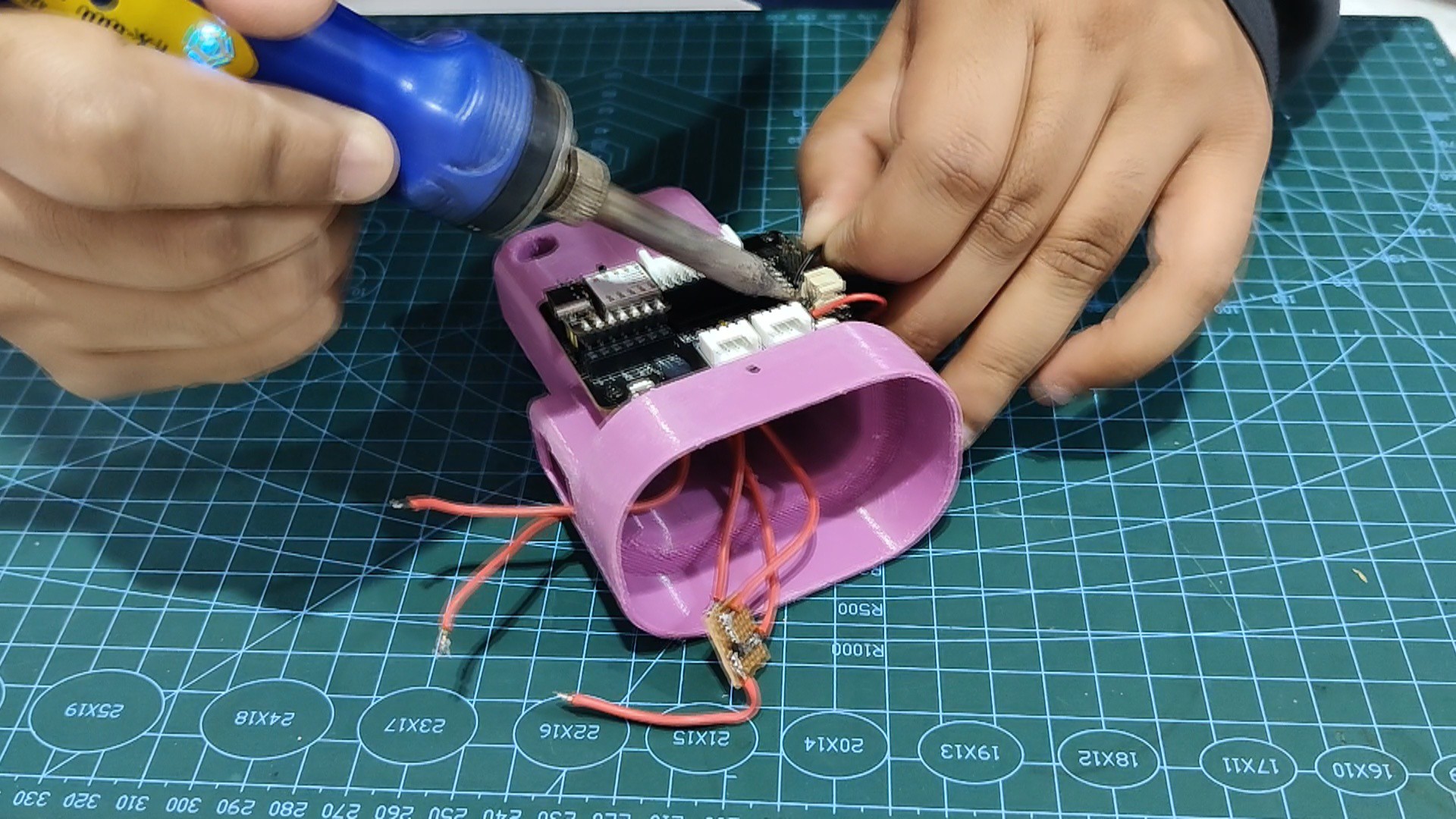
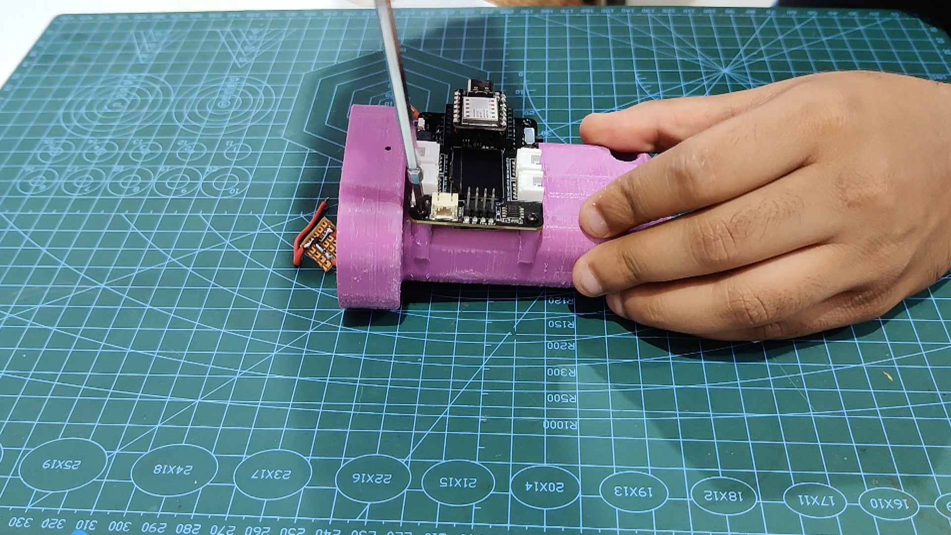
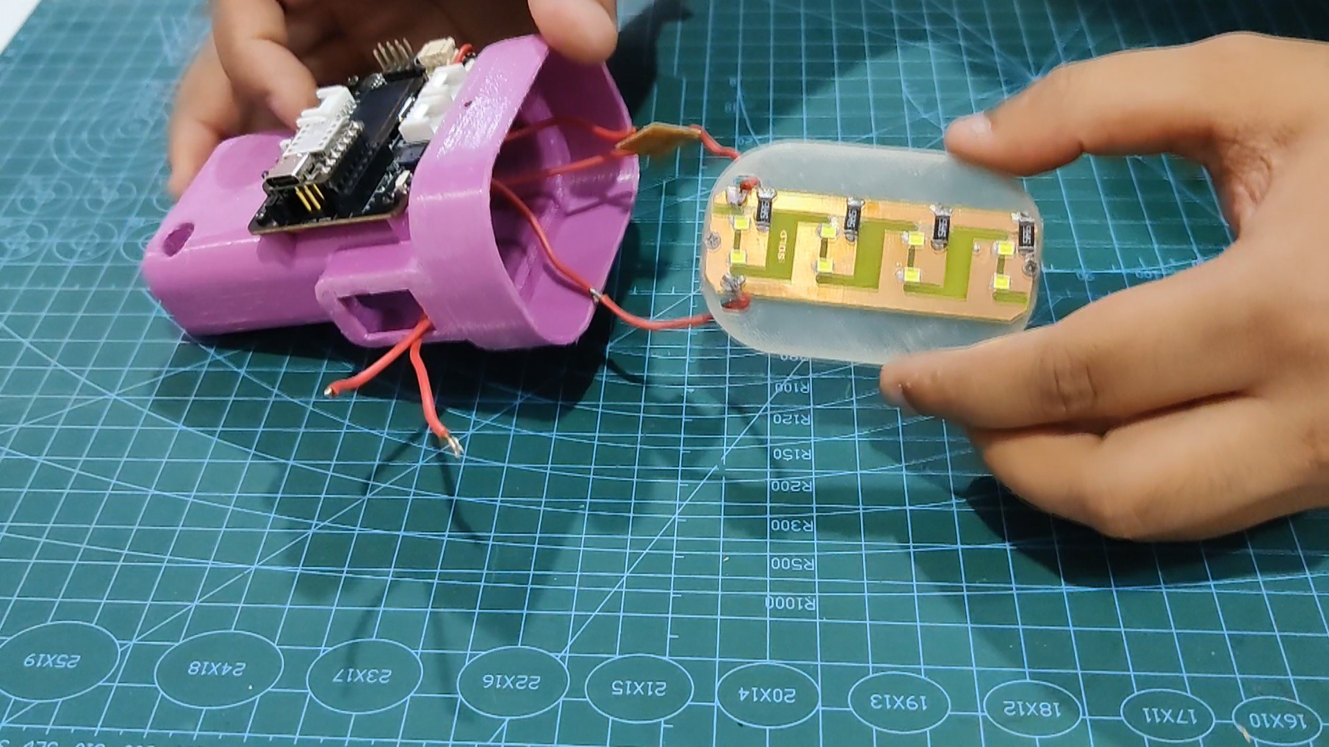
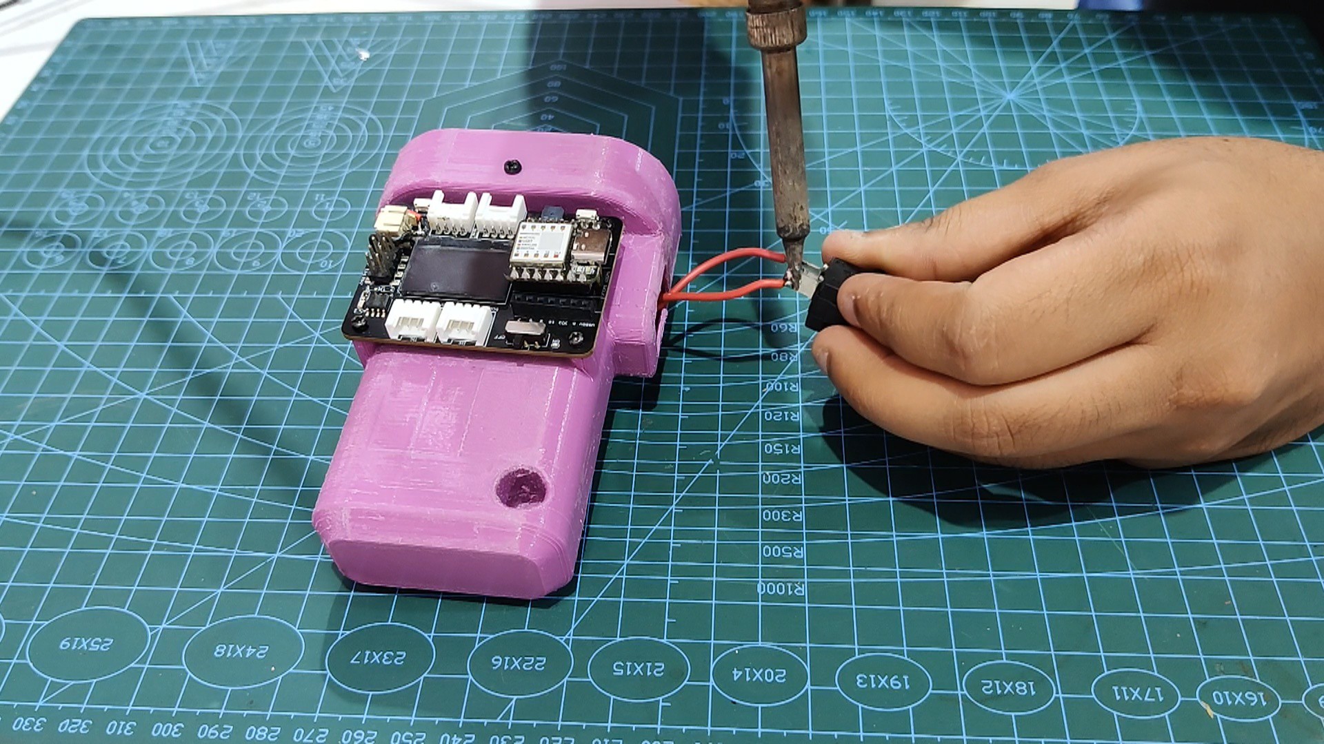
- Using a soldering iron, remove all of the parts from the XIAO expansion board, including the battery, switch, and LED load, to start the assembly process.
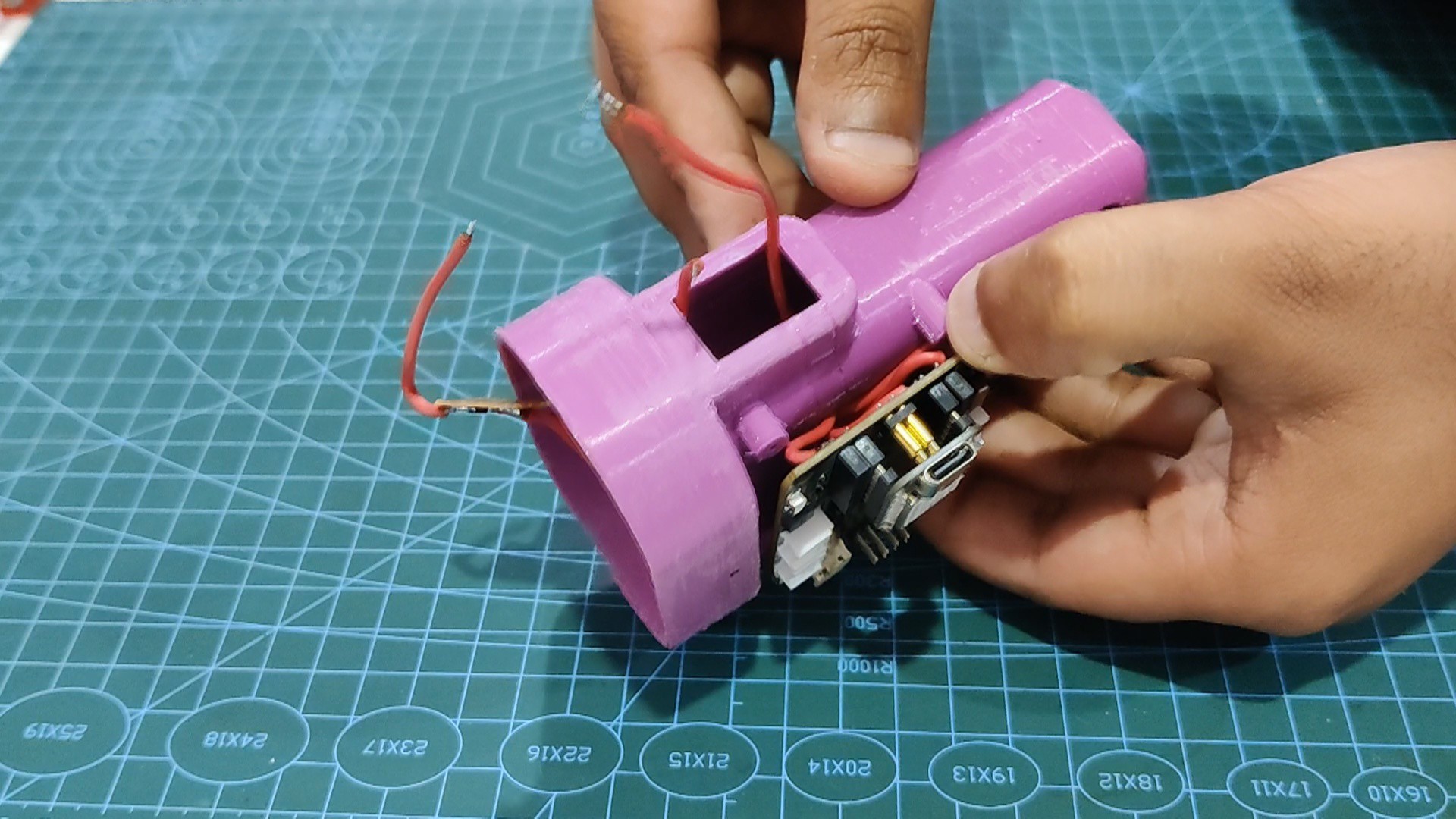
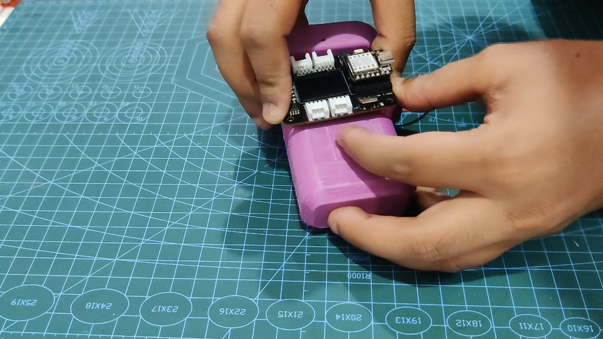
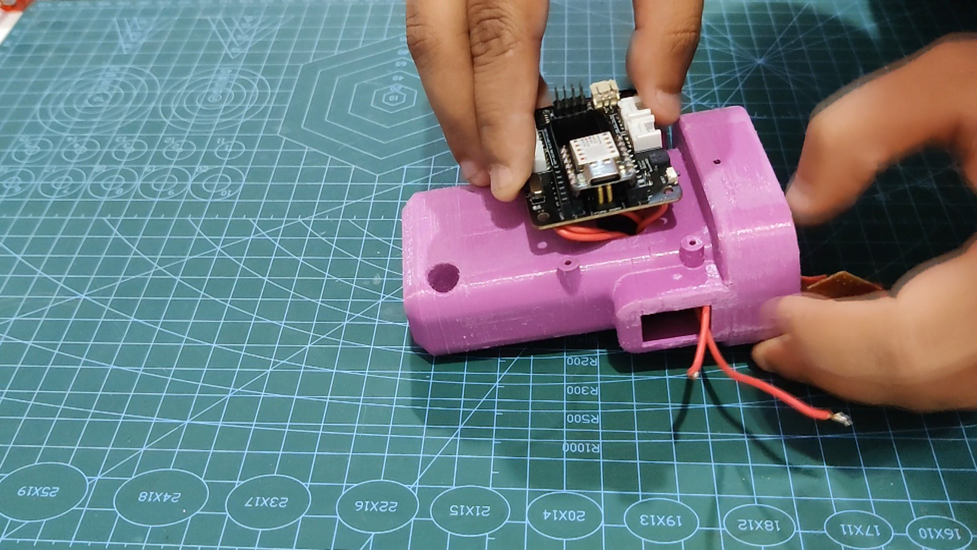
- Next, using a window provided on the expansion board mounting location, we select and position the expansion board on the main body before running all the cables inside.
- To permanently fasten the expansion board in its position, we utilize four M2 screws.
- The lithium cell was then installed in the main body.
- Next, we linked the expansion board to the positive and negative wires of the lithium cell.
- We turn the ON/OFF switch on the expansion board to confirm that the battery is connected to the board. When we do this, the XIAO SAMD21's status LED illuminates, indicating that the board is receiving power.
-
4FINAL ASSEMBLY
![]()
![]()
![]()
![]()
![]()
![]()
![]()
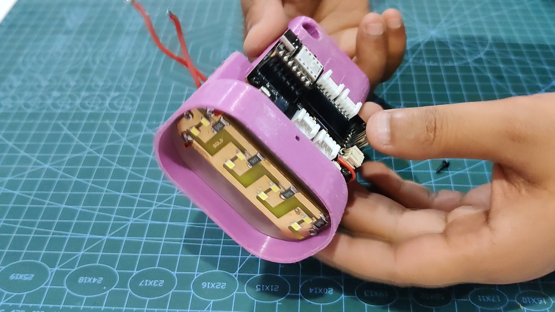
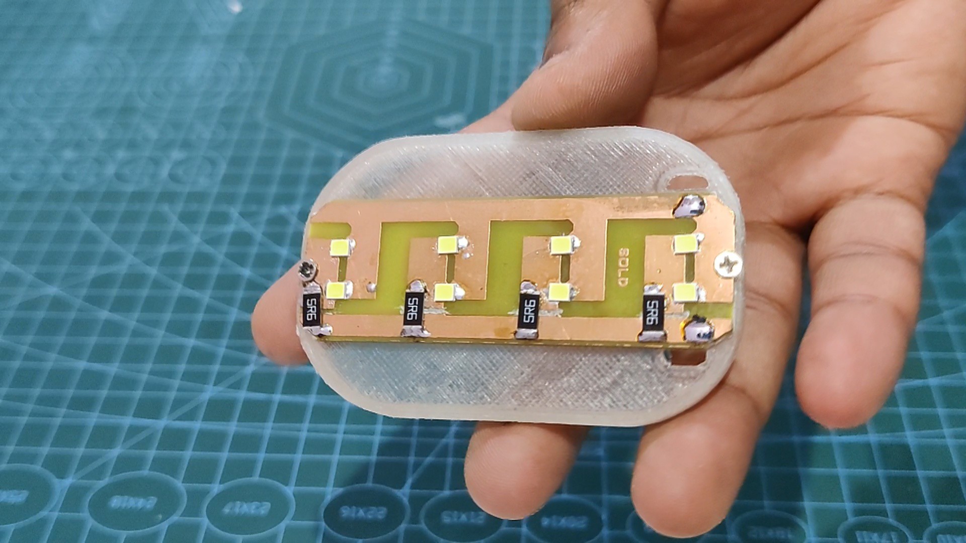
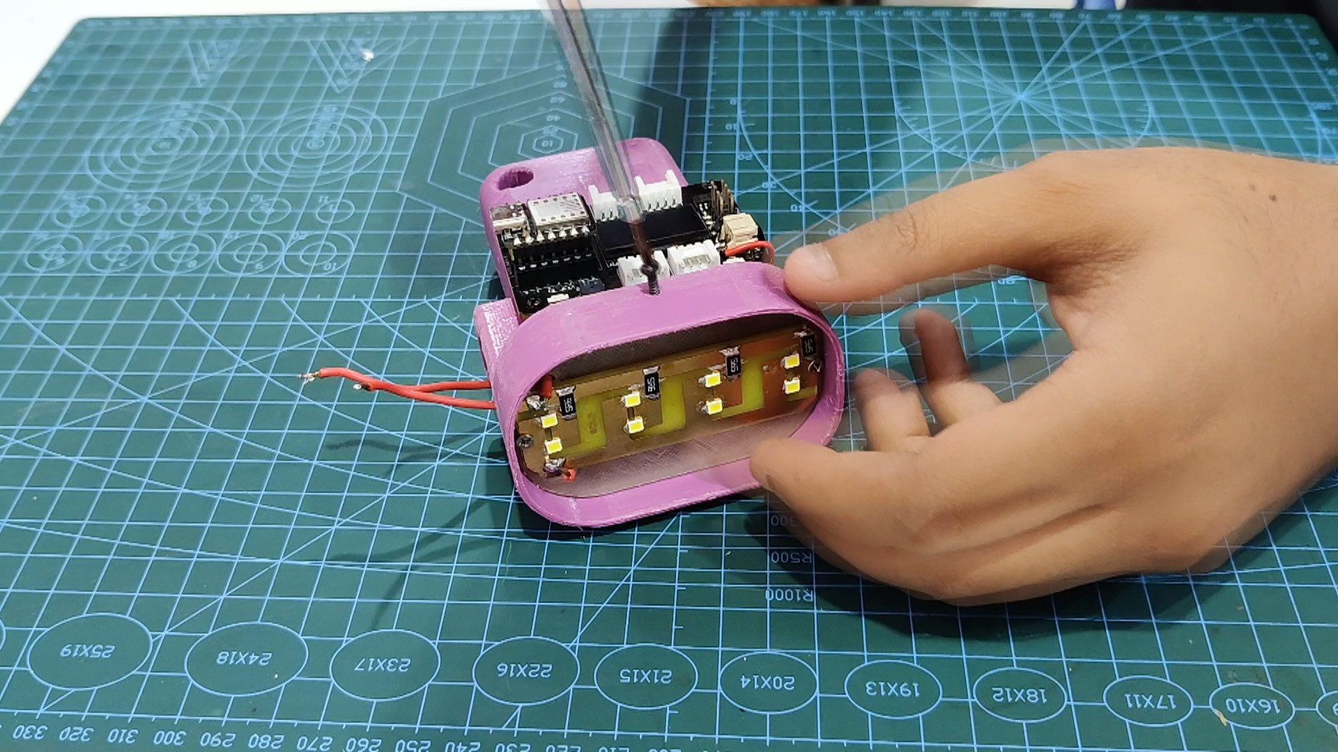
- In order to begin the final assembly procedure, we place the LED load on the PCB Holder component and fasten them both together with two M2 screws.
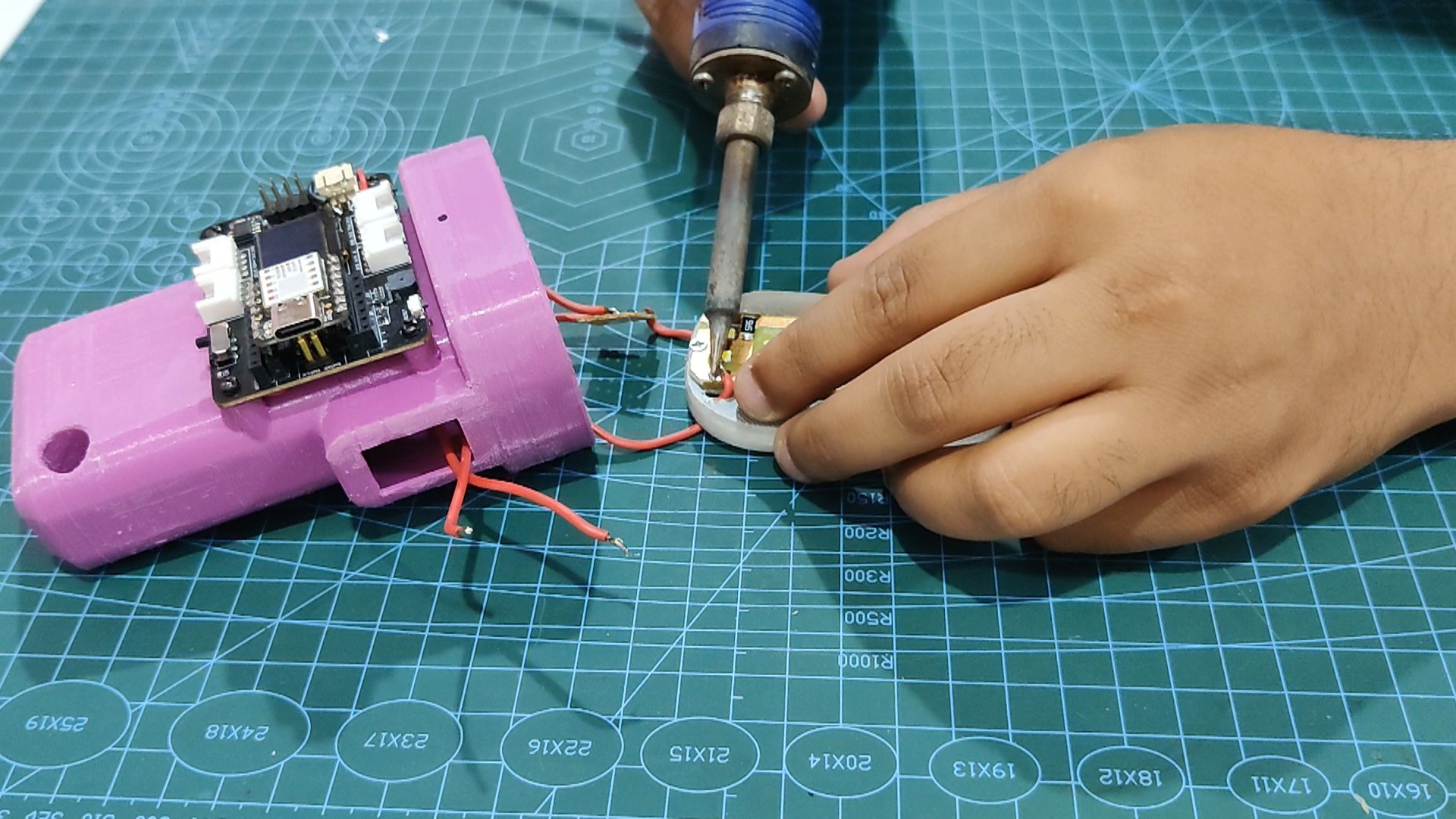
- The LED load's negative terminal will then be linked to the mosfet's drain. Next, attach the positive terminal of the LED load to the expansion board's 3V.
- Wires are connected to the LED load, and the PCB holder assembly is pushed into the main body. The PCB holder and main body are then fastened together with two M2 screws.
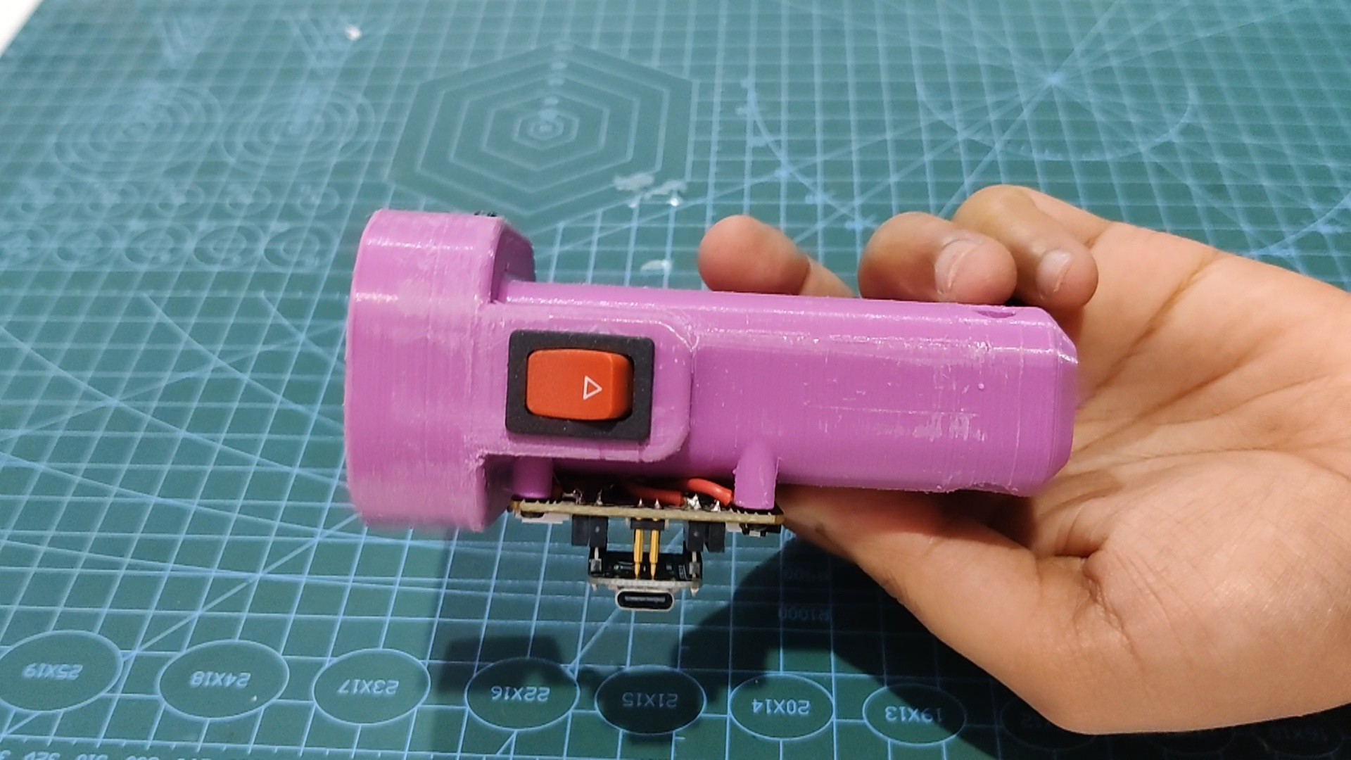
- Using a soldering iron, we finally reconnected the rocker switch to D1 and GND. After that, we pushed the rocker switch into place to finish the assembly process.
The flashlight is now ready.
-
5RESULT
![]()
![]()
We tested this arrangement outside in the woods to see how well it would perform for lighting up the area. The results are seen in the video.
Compared to conventional focus LED flashlights, the light spread angle of this flashlight, which is a flood light kind, is wider.
I will be using this item on an upcoming camping trip; it was a truly overengineered take on a basic yet essential thing.
Overall, this project was successful, however in order to cut down on wiring and makeshift processes we will soon be working on a Version 2 that will house the Mosfet as a switch configuration and LED array together on single PCB.
Thanks for reaching this far, and special thanks to Seeed Studio Fusion for supporting this project. Check them out for all sorts of PCB manufacturing and assembly services for great quality and less price.
Peace
Smart Flashlight with XIAO MCU
Made a smart Flashlight using XIAO Microcontroller paired with OLED Expansion Board.
 Arnov Sharma

Discussions
Become a Hackaday.io Member
Create an account to leave a comment. Already have an account? Log In.