Close
0%
0%

Remote Control SAO

A badge add-on that's a re-programmable remote for your TV or other IR-controllable device and a I2C-controlled IR blaster.

Similar projects worth following
When I saw that this year's SAO contest was about utility, I knew that I wanted to do something with infrared. In my day job, I've used lots of IR controls and also implemented the receiver side for a number of Roku TVs, but I never built hardware to actually send them.

When I saw that this year's SAO contest was about utility, I knew that I wanted to do something with infrared.  In my day job, I've used lots of IR controls and also implemented the receiver side for a number of Roku TVs, but I never built hardware to actually send them.

This SAO is still in-development, but the basic architecture is:

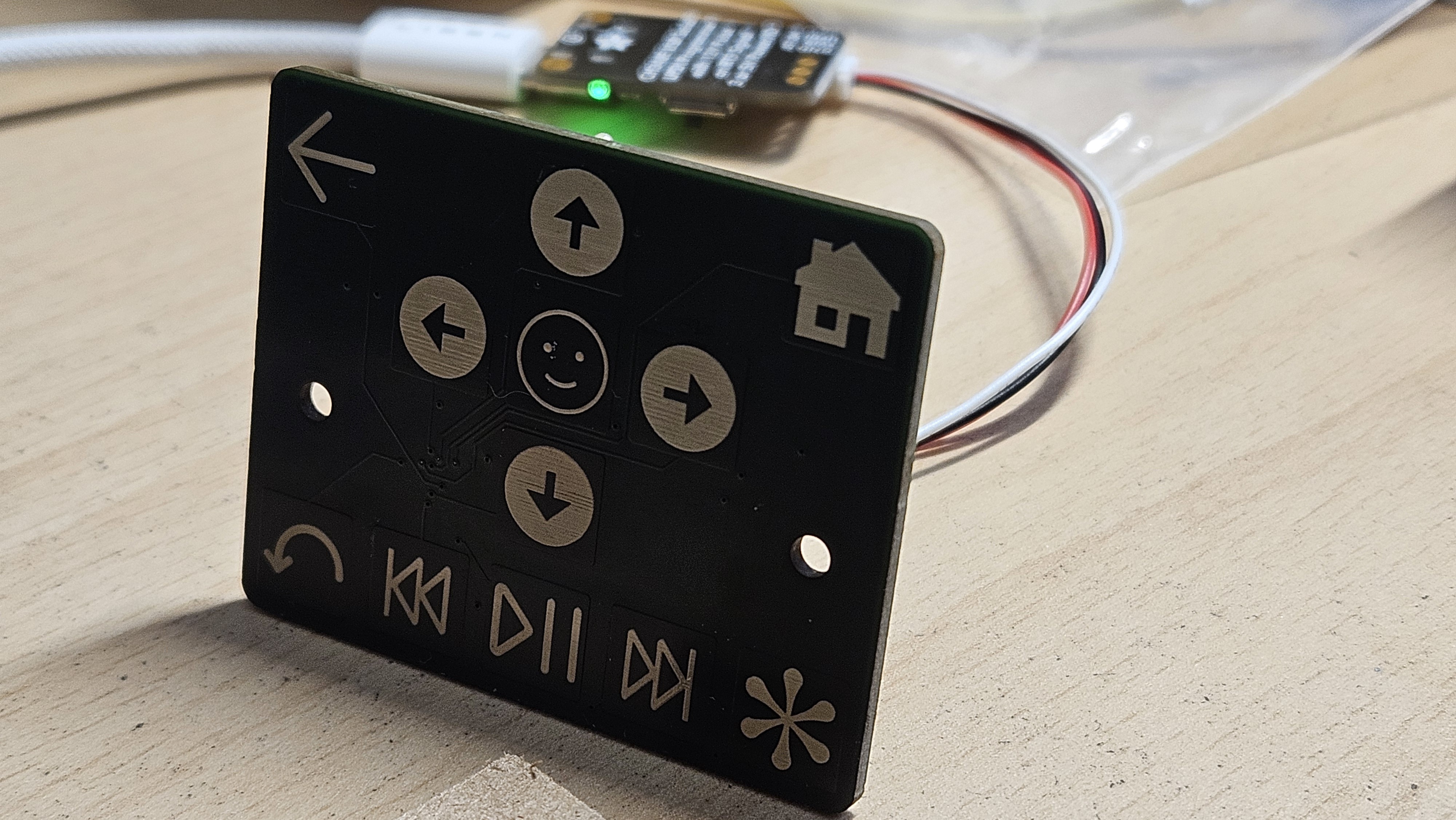
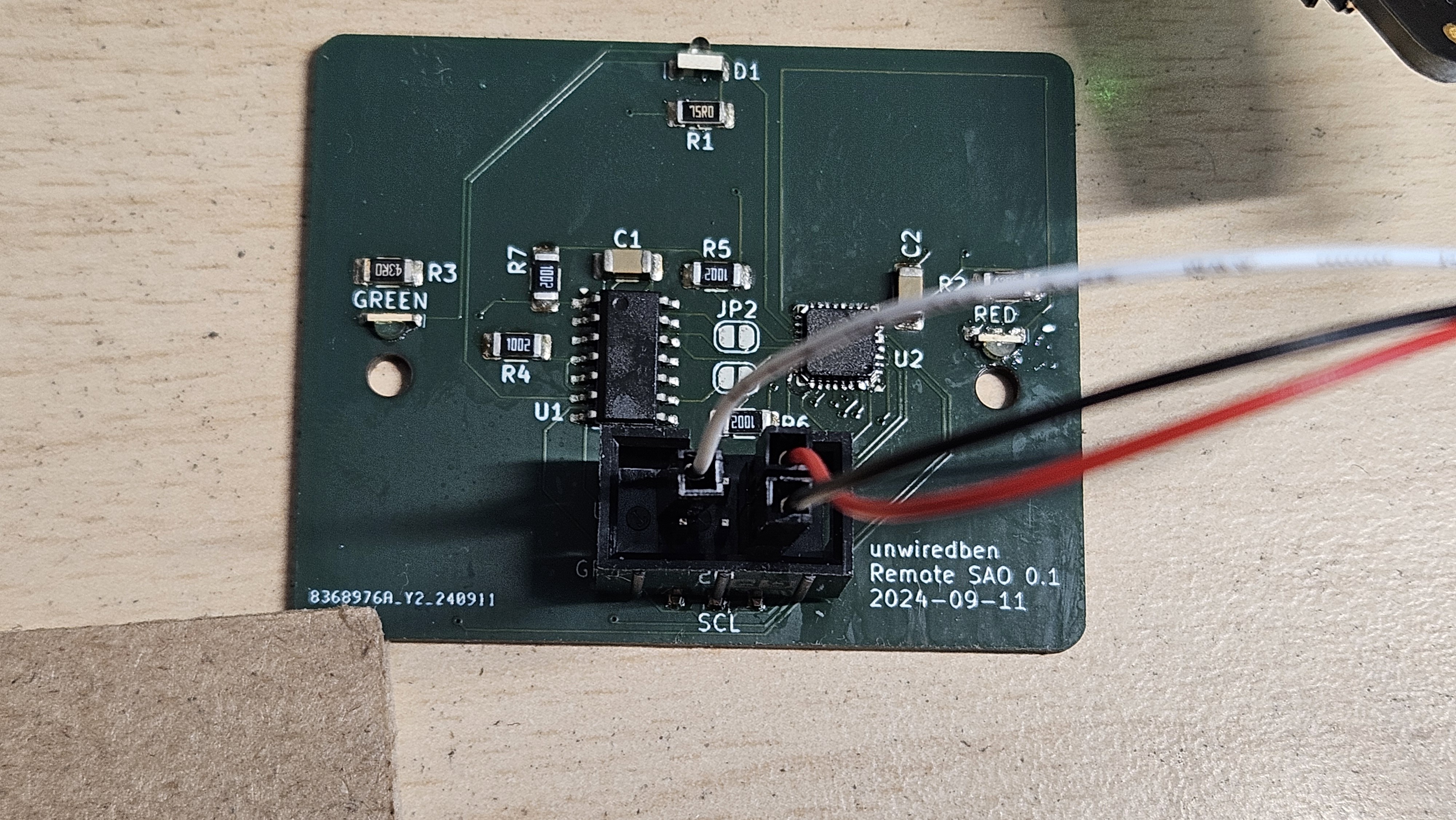
  • Microchip CAP1114 - 14-input capacitive touch sensor and LED driver - connects to twelve touch pads on the front of the SAO PCB and also controls a couple of single-color LEDs for status and blinky
  • Microchip ATTiny1614 - small and cheap MCU with lots of flash that will run the blinky lights, button scan, and directly control the IR emittter. This will either be an I2C master to control the CAP1114 or work as a I2C peripheral depending on a GPIO line.
  • Red and green side-mounted LEDs - these will shine through the FR4 PCB so you can see them on the front of the add-on
  • IR emitter - like a flashlight, but you can't see it.  Luckily, TVs can.
  • Touch pads - these are free, but require careful layout on the front of the PCB and fun art to go over the soldermask that covers them.
  • SAO connector - this supplies power and ground connections, has a I2C bus that we can connect to, and has two GPIOs that are used as a programming connector for the ATTiny1614 and a pin to enable peripheral mode.

  • Built a second board

    Ben Combee10/22/2024 at 07:49 0 comments

    I finally put together my second board for this tonight.  The assembly went a bit better due to better temperature control on my hot plate as well as use of my new video microscope, but my decision to add flux during the reflow wasn't my best, as it left the board a bit sticky.  This one programmed up quickly and ran my touch test code, and it has a much better chance of blinking LEDs because I managed to get all of them to solder on correctly.

    My coding tasks are currently:

    1. Fix touch code to reset state so I can read individual buttons
    2. Blink the two LEDs hooked to the touch sensor chip
    3. Send some test IR codes to my TV

    Alas, due to having a busy job and busy kids, my hacking time for getting this code up and running has been limited.

  • I2C Communication is working

    Ben Combee09/30/2024 at 06:06 0 comments

    I've now validated that I can talk to the CAP1114 chip.  This is the first time I'd used the I2C interface in the Arduino library, and I'm happy that there's a lot of good documentation in the megaTinyCore source.  My first attempt to read out the product ID, manufacturer ID, and revision registers resulted in 0xFFs, and I spent a lot of time checking what was wrong.

    First problem I found was that I'd wired the CAP1114 to the alternate I2C pins on the ATTiny1614.  The device defaults to using PB0/PB1, and those are connected to the I2C connector on the SAO, but I used PA1/PA2 for my wiring to the CAP1114.  Eventually after searching through various headers, I found the Wire::swap() call that's a megaTinyCore extension to the Arduino APIs, and was able to use that to reconfigure.

    My second problem was using the wrong address.  The datasheet talked about a product ID of 0x3A, so I'd assumed that was the address, then I re-read the protocol description and found that the read address was 0x28, although that was only found after decoding the binary to hex and shifting over one.

    Now that I got good reads from the ID registers, I started a serial dump from the button status registers, but those don't make sense yet.  I think I'll need to configure a few more parts of the chip to actually get the values I want from the touch pads.  I can tell some of them seem to be sensed, but they're not returning to an untouched state yet.

  • Boards have arrived!

    Ben Combee09/28/2024 at 15:21 0 comments

    While I was on a work trip, my boards and stencil arrived from JLCPCB.  It took a while for this delivery, as I used the slowest shipping, something I won't repeat.

    The order was sent on September 11, the manufacturing was done on 9/14 but not passed on to the shipping company until 9/16, then took nine days to get on a plane from Hong Kong to Illinois, then get shipped down to Georgetown, TX, then it took two days for them to be transferred to the USPS, and another day to my front door.

    Part of the problem was that I ordered a stencil with the board.  The stencil proved very useful to solder it up, but I didn't realize that JLCPCB had only one size and it's enormous.  I was expecting something a little larger than the board, but it was a 380mm x 280mm giant, wedged between pieces of hardboard.  That explains the $7 cost and the big addition to the shipping cost.

    This was my first time using a hotplate for SMD, and it went pretty well.  I picked up a 100mm x 100mm hotplate from Amazon a month ago, and it worked well, but I wasn't quite sure what setting to use.  I picked 350C and waited for board to reflow, but wasn't quite sure how long to leave it on, so my silkscreen got a little burnt, losing it's bright white appearance.  The hotplate comes up to temperature fairly quickly, but takes a while to lose temp.  On inspection, the only parts I needed to fixup were some bridges on the QFP32 touch controller and reworking the red LED.  The LEDs are all side mounted, which makes placing them by hand a little awkward.

    Here's the completed board!

    So far, I've successfully programmed the ATTiny 1614 using the UPDI programmer from AdaFruit, but I neglected to hook up a visible LED directly to the ATTiny, so it's hard to tell if code is running well.  By pure luck, I chose the TX line to hook up to GPIO2 on the SAO connector, so I managed to get serial output by just moving the programmer's pin between the two GPIO pins.

    My next step is getting some I2C communications going and verifying that the CAP1114 is working.  I'll setup a simple loop to test all the touchpads and blink the two LEDs connected to the CPA1114.  After that works, I've got to integrate the IR code sending logic, and then I'll have a working SAO, although it doesn't yet do anything with the I2C input.

  • Waiting on Boards and Hardware

    Ben Combee09/17/2024 at 20:43 0 comments

    Board order was sent to JLCPCB on September 11th, very early in the morning for me.  I also sent off my order to Digikey for all the parts, and those arrive today.

    $21 for five PCBs and stencil shipped, expected to arrive around 9/20.  I'm holding off a larger order until I verify correct operation

    From Digikey, where I ordered enough for 25 boards, plus extras where it made sense.

    1    CAP1114-1-EZK-CT-ND    CAP1114-1-EZK-TR    IC TOUCH SENSOR/LED DRVR 32VQFN        25    0    $1.43000    $35.75
    2    ATTINY1614-SSNRCT-ND    ATTINY1614-SSNR    IC MCU 8BIT 16KB FLASH 14SOIC        25    0    $0.83000    $20.75
    3    3147-B2581IR--20C000172U1930CT-ND    B2581IR--20C000172U1930    3.2(L)X1.6(W)X2.55(H) MM        50    0    $0.20000    $10.00
    4    1276-1097-1-ND    CL31B105KAHNNNE    CAP CER 1UF 25V X7R 1206        200    0    $0.04200    $8.40
    5    RMCF1206FT75R0CT-ND    RMCF1206FT75R0    RES 75 OHM 1% 1/4W 1206        500    0    $0.00876    $4.38
    6    RMCF1206FT43R0CT-ND    RMCF1206FT43R0    RES 43 OHM 1% 1/4W 1206        500    0    $0.00876    $4.38
    7    732-5025-1-ND    155124RS73200    LED RED CLEAR 1204 SMD R/A        50    0    $0.18800    $9.40
    8    732-5026-1-ND    155124VS73200    LED GREEN CLEAR 1204 SMD R/A        50    0    $0.18800    $9.40
    9    RMCF1206FT10K0CT-ND    RMCF1206FT10K0    RES 10K OHM 1% 1/4W 1206        500    0    $0.00876    $4.38
    10    1175-1864-ND    3020-06-0300-00    CONN HEADER SMD 6POS 2.54MM        25    0    $0.50700    $12.68
                                Subtotal    $119.52

    and from Amazon, about $150 worth of upgrades to my electronics workbench, including a bench power supply, a reflow hot plate, new iron tips for my Pinecil, SMD-ready solder paste, various kinds of flux, and a few other items.  I should be able to leverage all that on other projects, of course.

    I could definitely save some money on the BOM ordering connectors and LEDs from AliExpress or LCSC, but decided I didn't want to wait for multiple shipments from China.  I probably can use a cheaper ATTiny part too, but they're footprint compatible and wanted to get the larger flash space while developing.

View all 4 project logs

Enjoy this project?

Share

Discussions

Similar Projects

Does this project spark your interest?

Become a member to follow this project and never miss any updates