1 Sources of inspiration
As you probably know, there are a myriad of different kinds of nixie clock on the internet. You can easily find schematic for clock with any types of nixie tubes. However, schematic of all this clocks is kinda similar and the main component in them is Arduino or other microcontroller. Obviously, the main advantage of such solution is simplicity – you can easily implement various functions in your clock, like settings, alarm, digits transitions and so on. Basically, the most simple and common nixie clock requires the next components:
- Arduino UNO
- RTC module DS1307
- nixie tube driver k155id1 (К155ИД1)
Despite being very simple and affordable, to me such circuits look too basic, probably, they could be more useful and helpful for beginners, who have just started studying electronics or for those, who don’t wanna bother with schematics and want simple and reliable solution.
In order to challenge myself, I decided not to use microcontrollers and RTCs, instead I assumed it would be better to use discrete microchips like it was back in the 60-s and 70-s. I remember how once in my university I was given a task to design a digital clock on binary counters on Verilog for FPGA. The code was pretty straightforward – binary counters were counting upwards till their maximum value after what they reset back to 0. Totally, there ware six counters each for one digit and they all were connected together in series, after previous counter resets the next one increments its value. For some reasons I found such a schematic very attractive, probably because of its simplicity. After a while I decided that it would be great to build this circuit using real components and not on 7-segment displays but something more attractive.
Another source of inspiration for this project were nixie tubes that I had. Every time I watched at them I thought how grate it would be to make digits in this tubes glow again. This clock has four IN-12 tubes, two for hours and minutes, and two IN-17 tubes for seconds. In the internet there are not a lot of variations of clocks with big digits for hours and minutes and smaller ones for seconds, so I assumed that such disproportion in digits’ size would look interesting.
2 Schematic
In this section I will describe separate blocks of the clocks’ schematic to make it easy to understand. In general, there are four blocks:
- Clock control – block which supplies entire clock and provides inputs to set and show time;
- Clock core – basically the heart of the clock. It contains binary counters which count time. Also this block generates high voltage for nixie tubes;
- Clock mux – contains multiplexers that convert counters’ binary values into decimal numbers;
- Clock display – basically just a display made of six nixie tubes;
3 Clock control
Schematic of control circuit is shown on figure 1. As it can be seen this circuit is very straightforward. The main sub-blocks are: battery protection, DC-DC step-up converter to 5V, three buttons to set hours, minutes and seconds and “wake-up” circuit.
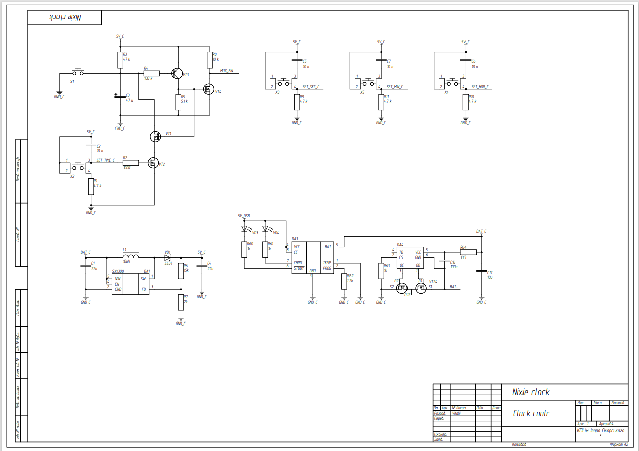
Figure 1.
Battery protection as mane suggests is needed to protect Li-Po battery from short circuits and over discharge. DC-DC converter provides 5V supply voltage for IC’s. The choice was made in favor of 5V because the high voltage binary to decimal converter K155ID1 (К155ИД1) needs 5V to operate properly, this component is crucial for displaying digits on nixie tubes.
Three buttons that “sets” hours, minutes and seconds control CLK multiplexers which sets CLK source for each of digit pair in clock. There are three digit pairs for every part of time (hours, minutes and second) and each consists of two digits – one digit represents most significant digit in number (aka tens of hours/minutes/seconds) and the second one represents the least significant digit (aka ones of hours/minutes/seconds).
The last sub circuit is “wake-up” circuit that...
 Vitalii

 Marten Electric
 Mitsuru Yamada
 Scoops
 zst123
The circuit boards are beautifully composed! I think the wooden casing also matches the atmosphere of the Nixie tube, and the whole clock is beautifully retro and futuristic.