Lifetime fails project
Every person makes mistakes, wise person learns from them.
Every person makes mistakes, wise person learns from them.
To make the experience fit your profile, pick a username and tell us what interests you.
We found and based on your interests.
This is not fail as such, but I believe it is good lesson learned and also trick to have in a sleeve, so I will publish it here (maybe just for future myself being lost again).
When connecting MCU to PC via USB, it is quite useful to fit external pull-up resistor in series with MCU controlled PFET to 3.3V supply. This allows you to turn the pull-up off and on during MCU boot and inform USB hub to re-enumerate your device without re-inserting the connector (for instance during debugging sessions).
A USB device must indicate its speed by pulling either the D+ or D- line high to 3.3 volts. A full speed device, pictured below will use a pull up resistor attached to D+ to specify itself as a full speed device. These pull up resistors at the device end will also be used by the host or hub to detect the presence of a device connected to its port. Without a pull up resistor, USB assumes there is nothing connected to the bus. Some devices have this resistor built into its silicon, which can be turned on and off under firmware control, others require an external resistor.
https://www.beyondlogic.org/usbnutshell/usb2.shtml
/*******************************************************************************
                       LL Driver Callbacks (PCD -> USB Device Library)
*******************************************************************************/
/* MSP Init */

void HAL_PCD_MspInit(PCD_HandleTypeDef* pcdHandle)
{
  GPIO_InitTypeDef GPIO_InitStruct;
  if(pcdHandle->Instance==USB)
  {
  /* USER CODE BEGIN USB_MspInit 0 */

    GPIO_InitStruct.Pin = GPIO_PIN_12;
    GPIO_InitStruct.Mode = GPIO_MODE_OUTPUT_PP;
    GPIO_InitStruct.Pull = GPIO_NOPULL;
    GPIO_InitStruct.Speed = GPIO_SPEED_FREQ_HIGH;
    HAL_GPIO_Init(GPIOA, &GPIO_InitStruct);
    HAL_GPIO_WritePin(GPIOA, GPIO_PIN_12, GPIO_PIN_RESET);
    HAL_Delay(5);

  /* USER CODE END USB_MspInit 0 */

    /**USB GPIO Configuration
    PA11     ------> USB_DM
    PA12     ------> USB_DP
    */
    GPIO_InitStruct.Pin = GPIO_PIN_11|GPIO_PIN_12;
    GPIO_InitStruct.Mode = GPIO_MODE_AF_PP;
    GPIO_InitStruct.Pull = GPIO_NOPULL;
    GPIO_InitStruct.Speed = GPIO_SPEED_FREQ_HIGH;
    GPIO_InitStruct.Alternate = GPIO_AF14_USB;
    HAL_GPIO_Init(GPIOA, &GPIO_InitStruct);

    /* Peripheral clock enable */
    __HAL_RCC_USB_CLK_ENABLE();

    /* Peripheral interrupt init */
    HAL_NVIC_SetPriority(USB_LP_IRQn, 5, 0);
    HAL_NVIC_EnableIRQ(USB_LP_IRQn);
  /* USER CODE BEGIN USB_MspInit 1 */

  /* USER CODE END USB_MspInit 1 */
  }
}
I hope this helps someone in the future. Im wondering whether this is fully compliant routine to re-enumerate USB device and Im using external pull-up and PFET all the time redundantly? Please comment if you know the answer :)
The goal was to convert signal 0 - 5V centered around 2.5V. It was evaluation of better ADC for precise measurement instrument. AD7691 18-bit SAR ADC was chosen. Nice differential input, 250ksps, great linearity, low errors. I made gain calibrations (real output voltage vs adc measured voltage) for the instrument and the results were shocking. Upper 25% of range was bullshit ( stuck codes, missing codes, even codes that corresponds to 19bit ADC :) ) and measurement was not to be trusted. Hmm I have probably damaged internal circuitry by accidentally increasing VDD to 8V for short period of time. But changing ADC didnt help. Problem was elsewhere.
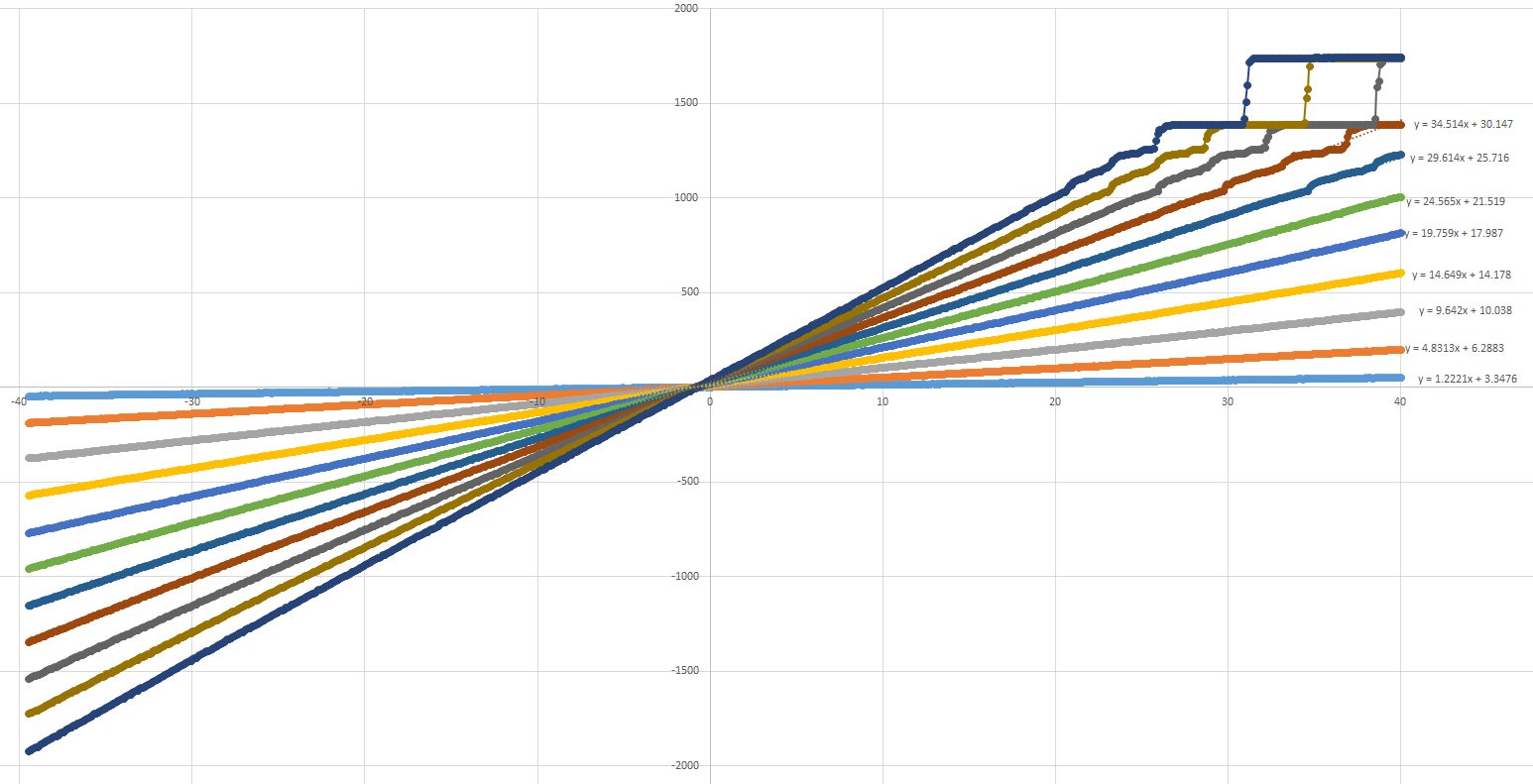
( http://electronics.stackexchange.com/questions/114825/stuck-codes-in-samples-from-adc )
Visiting datasheet again I have found one funky value I wasnt checking during the design because I have expected common mode range to be 0 to VREF, but LOL it is VREF/2+-0.1V. This means that I cannot feed VREF/2 signal to negative ADC input, but negative copy of my signal centered around VREF/2 instead.
Long story short AD7691 is true(fully) differential unipolar ADC and my signal was for pseudo-differential bipolar ADC or true differential with wide common mode ADC :-)
Simulation says it works, common mode is in range.
Solved :)
When I was working on one of my projects I needed to filter analog signal above 10Hz... or above 1000Hz... whatever. Well I decided to add a second order low pass filter instead of simple first order to get rid of that ugly and nasty noise :)
General Sallen-Key low pass filter topology is nice, with some symmetry it is very easy to calculate gain, time constant and other stuff. It was working as expected until variable gain possibility was added.
Here Im going to mention filter quality factor Q which is a design parameter of filters. Q provides a measure of sharpness to the stage frequency response. High Q implies a very narrow sharp frequency response. Low Q provides a wide shallow frequency response. But high Q makes an oscillator from your filter, which I wasnt aware of :) See below what I have designed and constructed and the simulation in LTSpice (great piece of software - thank you guys) of a violent oscillations with higher gain :) Transient simulation of frist 250ms after startup, while stepping feedback resistor value to set gains to 1x, 2x, 3x, 4x, 5x, 6x. Anything above 2x oscillates.
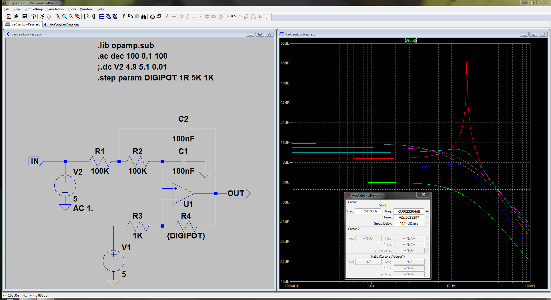
This was just an inspiration to see what can go wrong with active filters of higher order. I recommend you to read free document from Texas Instruments: Active Filter Design Techniques (excerpted from op amps for everyone).
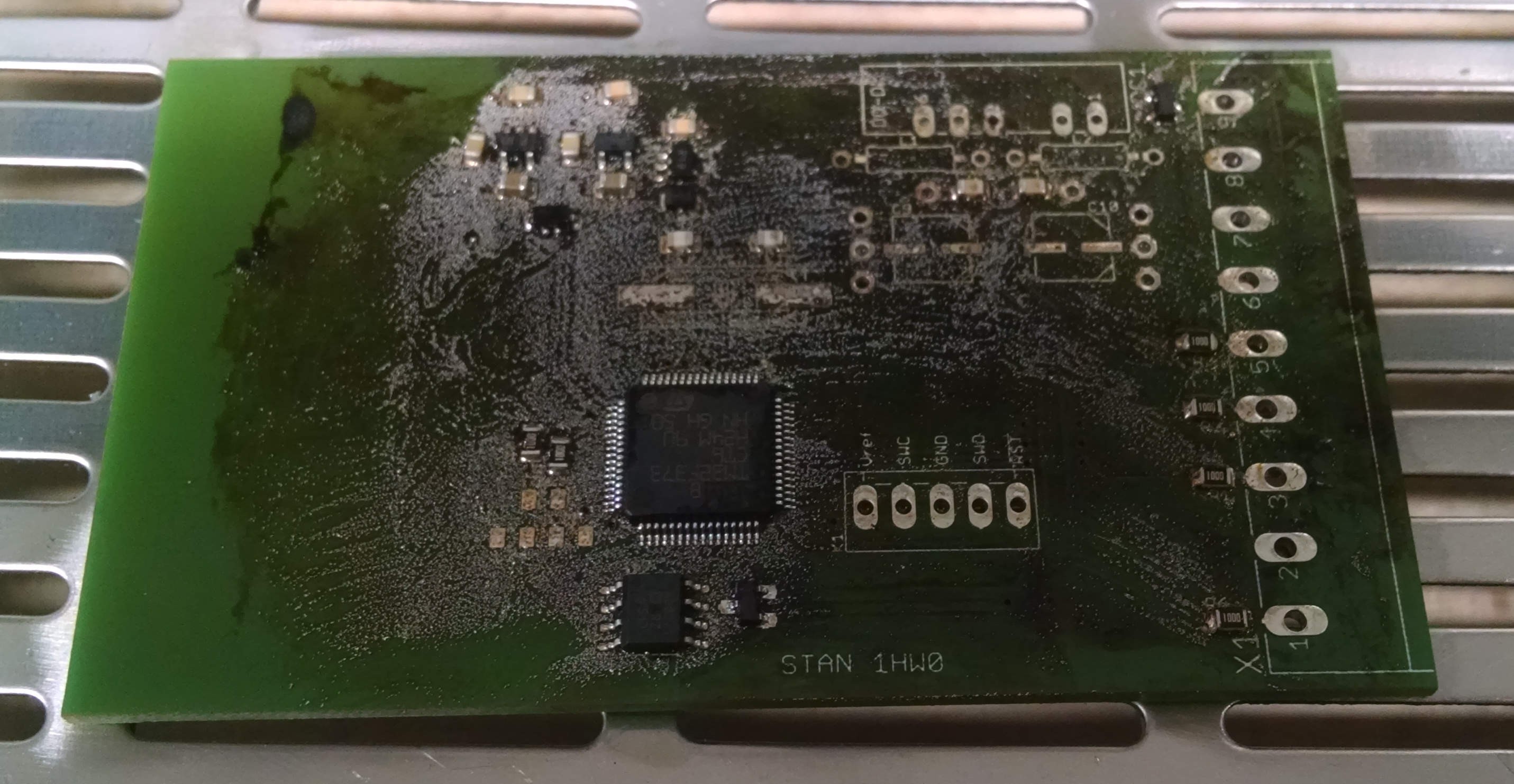
This is just a quick starter or project icebreaker :) Maybe more fun, but in reality it was fail because I was very naive thinking I will spread thin layer of solder paste all over the PCB, place all the components and reflow it in oven and clean all the remaining peaces of unused solder.
Well you can see the fruit of my naiveness
on the picture below. Dont do it, it wasnt possible to clean the board at all :)
Create an account to leave a comment. Already have an account? Log In.
Thanks. Im gladly going to invite all the people willing to share their fails. Do you want to start with sharing yours? :)
Great idea. You should invite people to join as collaborators to share their own project fails.
Become a member to follow this project and never miss any updates
 Dhruv Gramopadhye
 Gee Bartlett
 TEC.IST
 Samuel
Hey kevarek, this is very cool, really and what timing you have. I have been doing research on using cmos web cam (the JDEPC-05) for use as a spectrometer detector's image sensor, well, it did work until I changed my spectrometer design (which was planned,) to a more sophisticated design for Raman spectroscopy, (czerny-turner configuration.)
I overlooked one critical factor throughout the entire time, that the cmos sensor was able to work because it only had to translate the incident light image as it struck the DVD grating only 2mm away from the lens, with my new design ( a two mirror design,) the image strikes the 1st mirror, then strikes the diffraction grating, which in turn strikes the 2nd mirror, which focuses the image towards the detector.
Out of the year that I have been doing this, one would have thought that I would have realized that once the image leaves the 1st mirror and strikes the diffraction grating that, the image is dispersed into it's constituent and respective wavelengths before every string the 2nd mirror...what did that mean? big fat DUH!
A spectral image ( from blue to red,) spread out about 50mm wide! Lesson learned, (after 600 pages of research notes,) always pay attention to the small details :)