 likorne30
Version: 03/04/25
Ohmic geometry
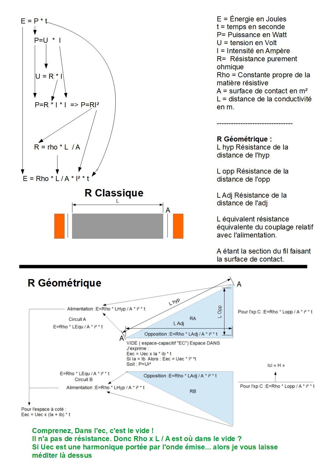
A) R=Rho x L equivalent / A
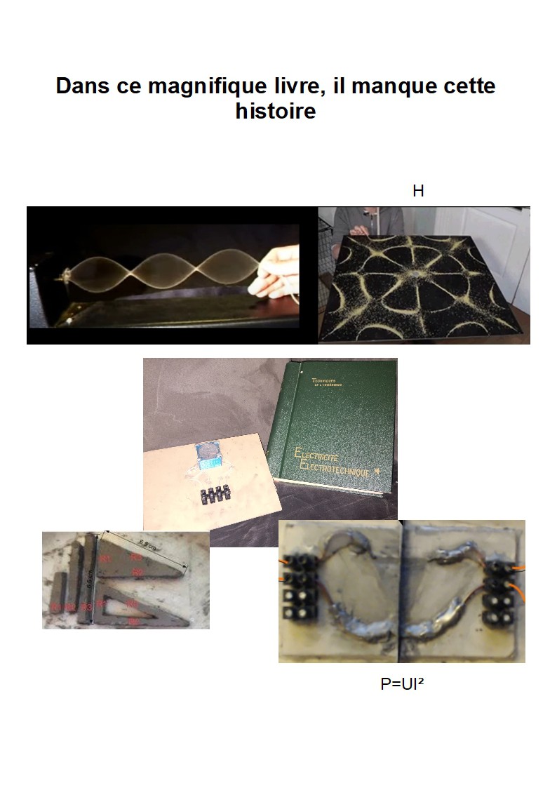
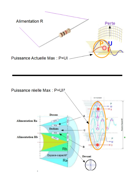
B) P=UI²
C) H in volt per m²
Google Doc :
https://docs.google.com/document/d/1p810H6pnS8E53QHrJ6wvpdmq0YnMisl6N-uKZO5tVak/edit?usp=sharing
Xp C :
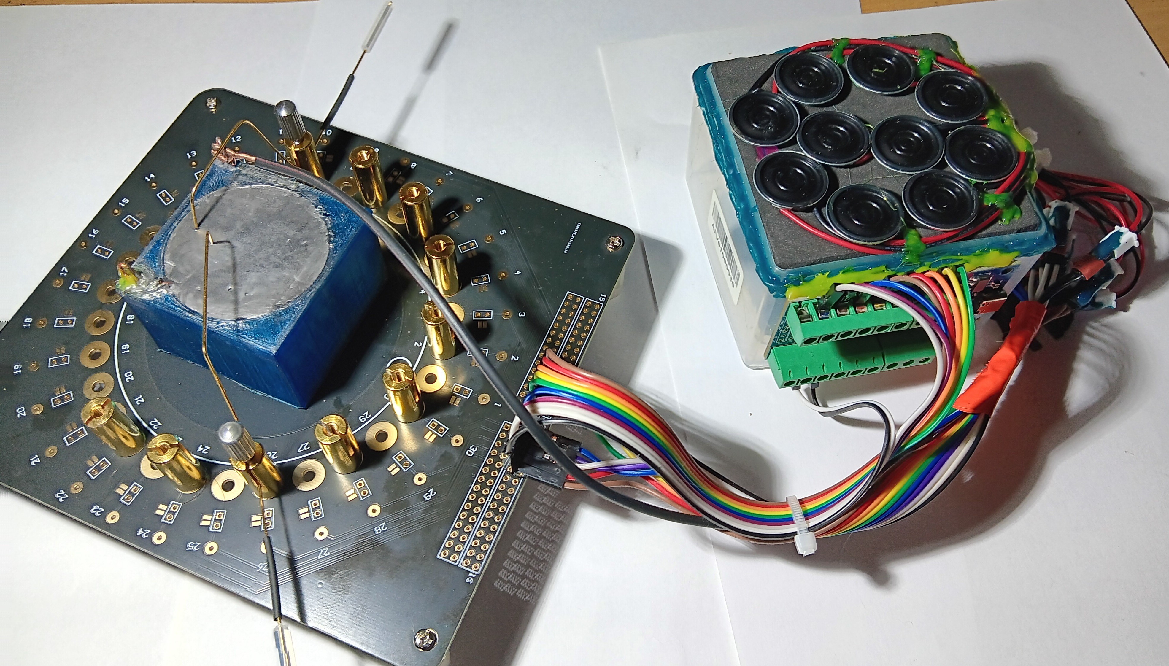
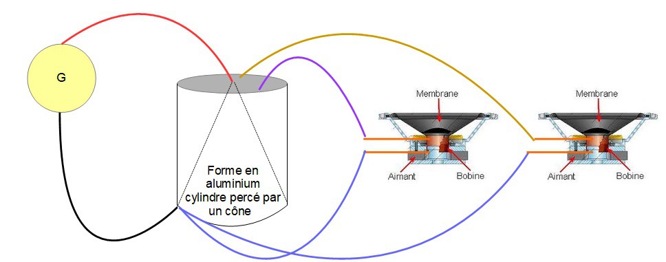
An aluminum cylinder pierced with a cone.
2 power wires
And
9hp, or 18 wires
all touch the aluminum block, it is an indirect short circuit.
My question remains the same, what is the current flow?
Would you like me to test it in three phases?
XP C :
The geometry of ohmic resistances: exploration and ABCD experiments
These forms of ohmic resistances allow to make assemblies.
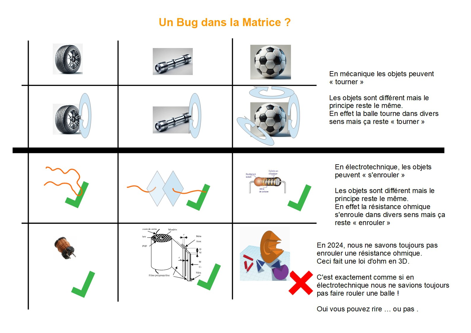
Like a coil allows to make a transformer or a motor.
Here, these are ohmic resistances which by their forms allow different assemblies.
These assemblies allow things that are normally considered impossible.
You can reproduce the experiments.
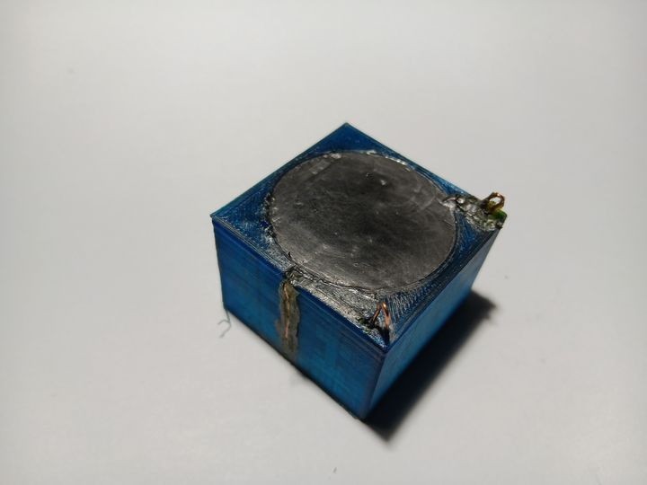
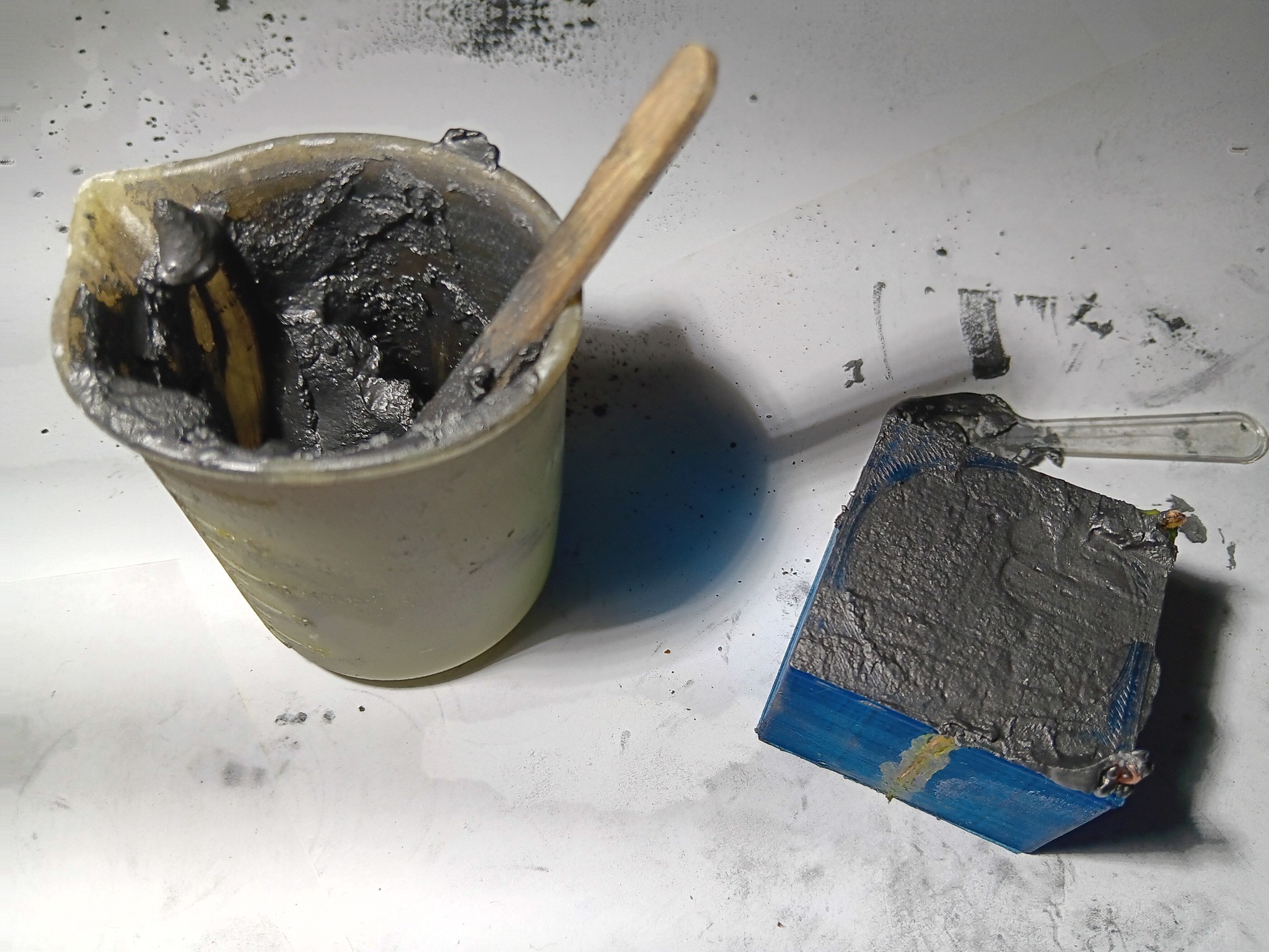
I make my ohmic resistances with plaster and graphite.
I make a paste that I pour into molds or that I cut with a cutter.
these are not good resistances but it allows to do the tests.
the goal is to compare a classic resistance VS a geometric resistance. this allows us to realize the differences.
On my fpv drone website, there too I talk about technique through tutorials, a logic of three in the sticks.. in other words piloting with the help of maths :D it's exciting, but that's not the subject.
My site is a private medium, I also made a presentation on the subject of geometric resistances that you can translate.
I also have a youtube channel but I speak French: https://www.youtube.com/@geometrieohmique
Indeed, the images are in French.
if you have gpt, you can translate the image.
With your phone's camera, you can also translate.
Let's try our best to overcome this language problem.
______________________________________________________________
Principle of my xp 😃
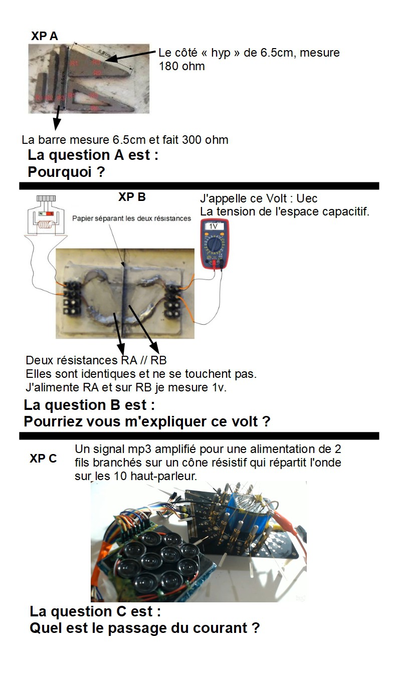
xp A is in B and C and demonstrates Ohm's law in 3D
xp B, demonstrates Uec, A voltage in volts relative to the loss.
xp C, demonstrates H, a cymatic in volts
xp D, is only B and C nested, for a presumed interaction between Uec and H.
______________________________________________________________
This project focuses on an in-depth study of the geometry of ohmic resistance and the exploration of three-dimensional interactions. Here is an overview of the four main experiments:
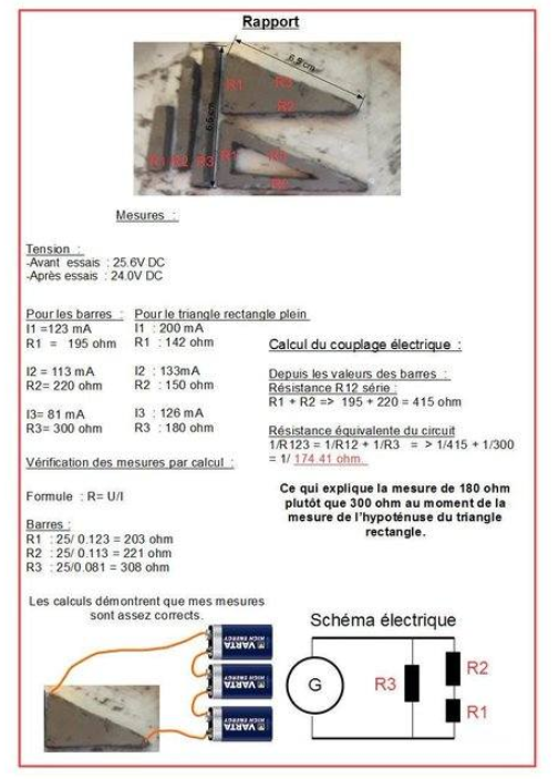
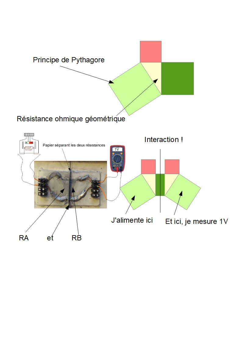
Experiment A: Geometrical coupling of resistors
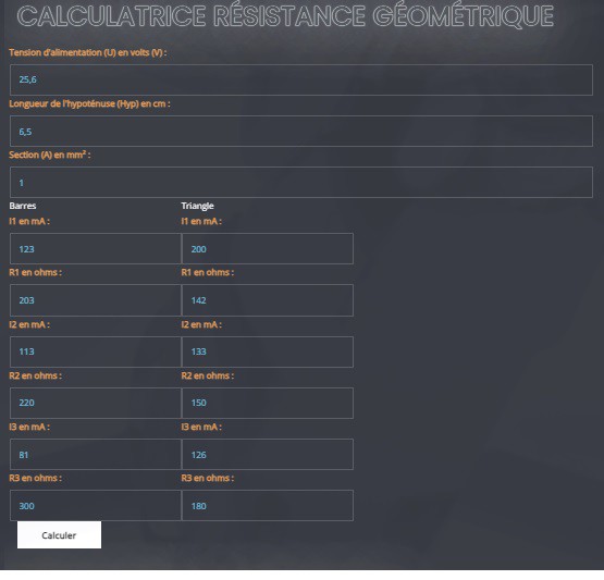
Experiment A examines how the coupling of resistors, arranged in a geometric configuration (triangle), influences the equivalent resistance. By adjusting the contact area, the resistance is intrinsically modified, showing the direct impact of geometry on conductivity.
I have coded a calculator on my website.
You can do the experiment and your measurements as well as calculate the accuracy of your measurements. The code is accessible in the accordion menu; geofpv.ch/crg-v1
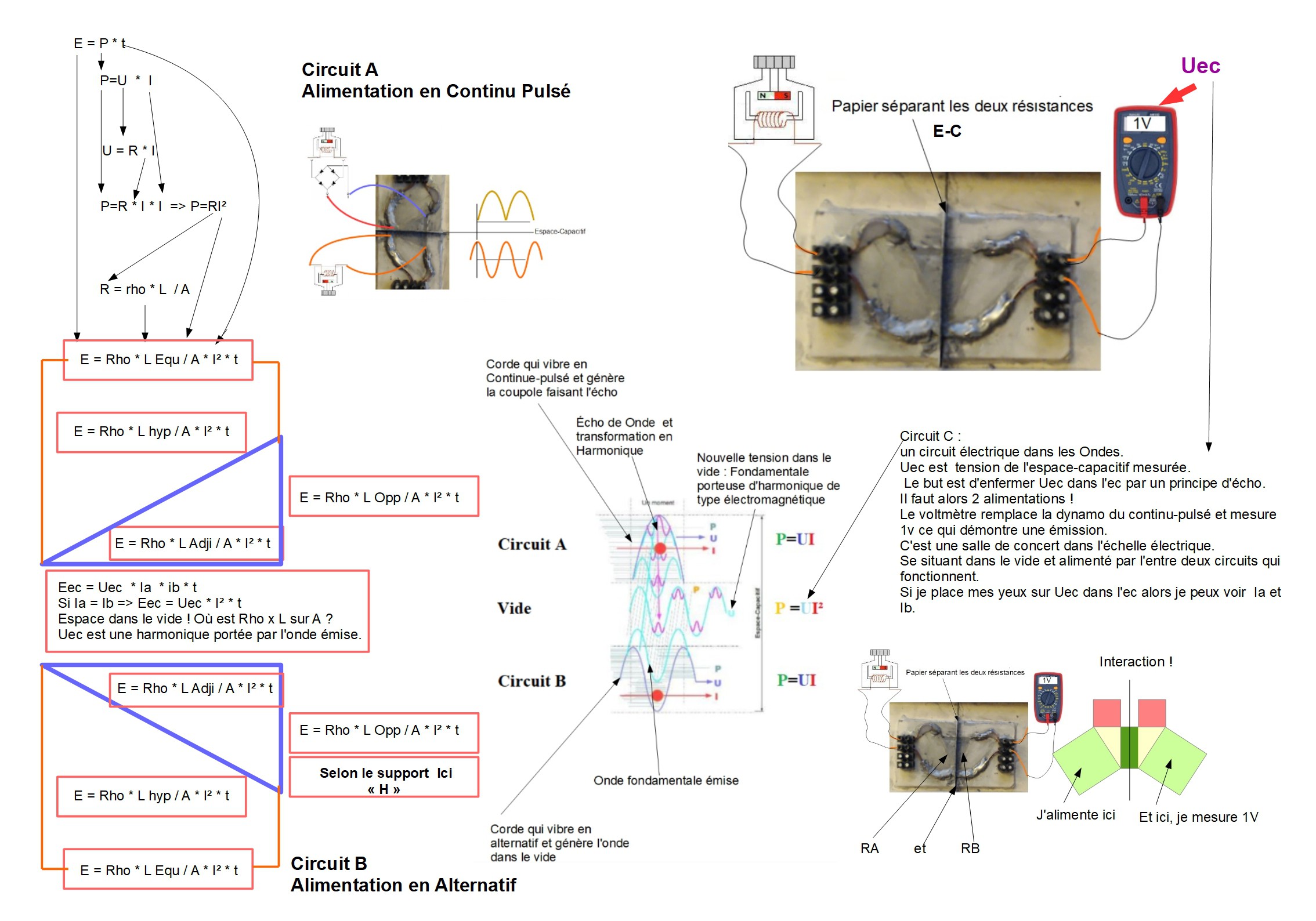
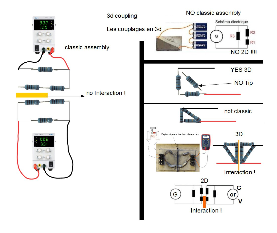
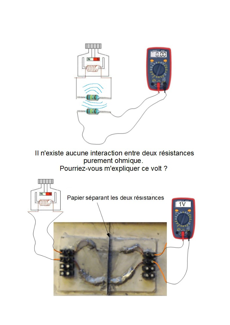
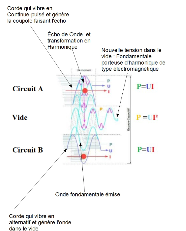
Experiment B: Ohmic Interaction and Echo Principle
In this experiment, I am currently measuring 1 V , proving an interaction between two resistors across the capacitive gap ( Uec ). The next step is to replace the voltmeter with a dynamo to capture and enclose this echo in the capacitive gap ( ec ). The goal is to enclose the measured voltage in the EC (enclose the loss)
(At no point do I talk about over-unity energy.)
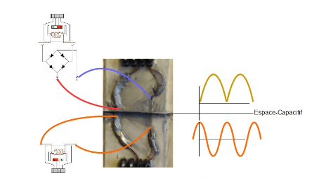
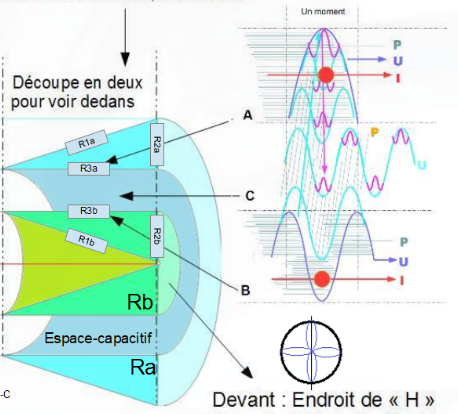
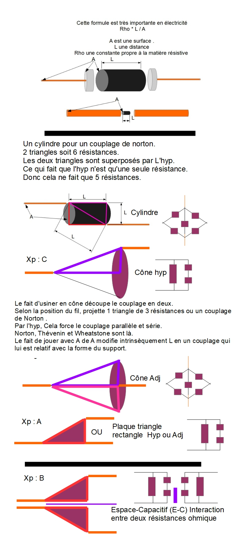
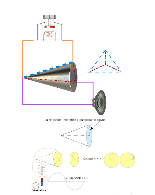
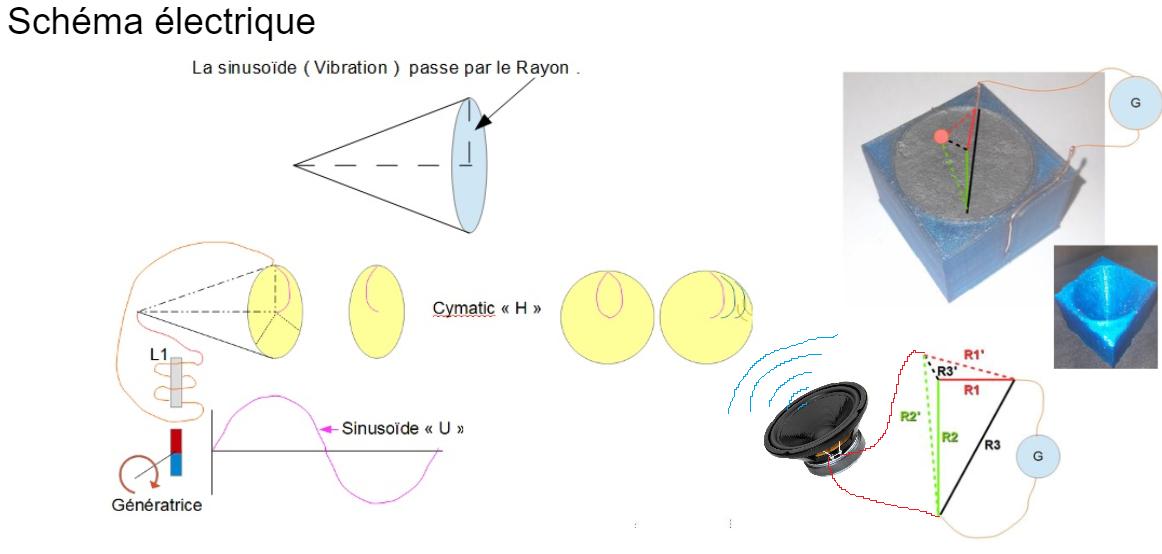
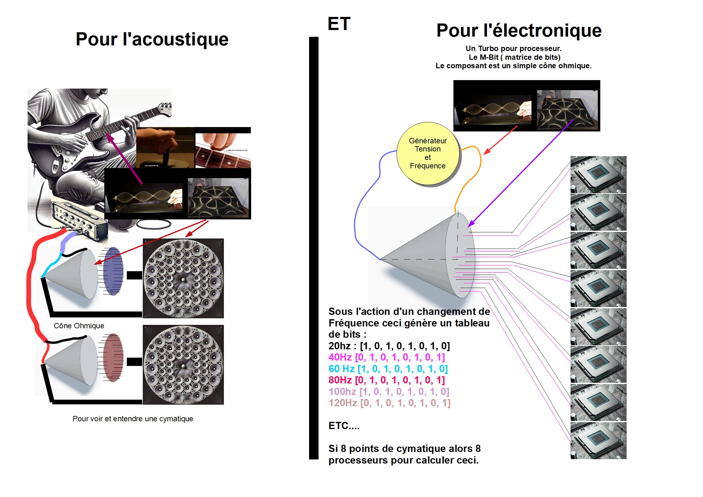
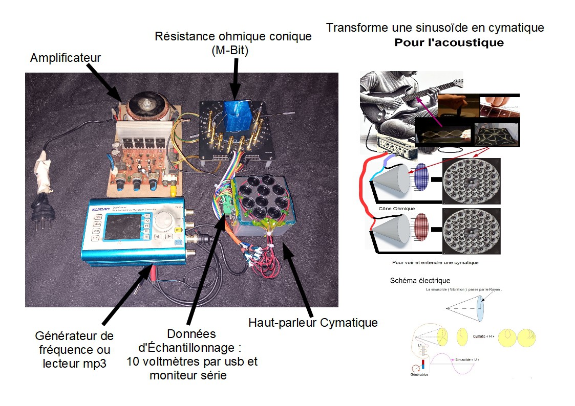
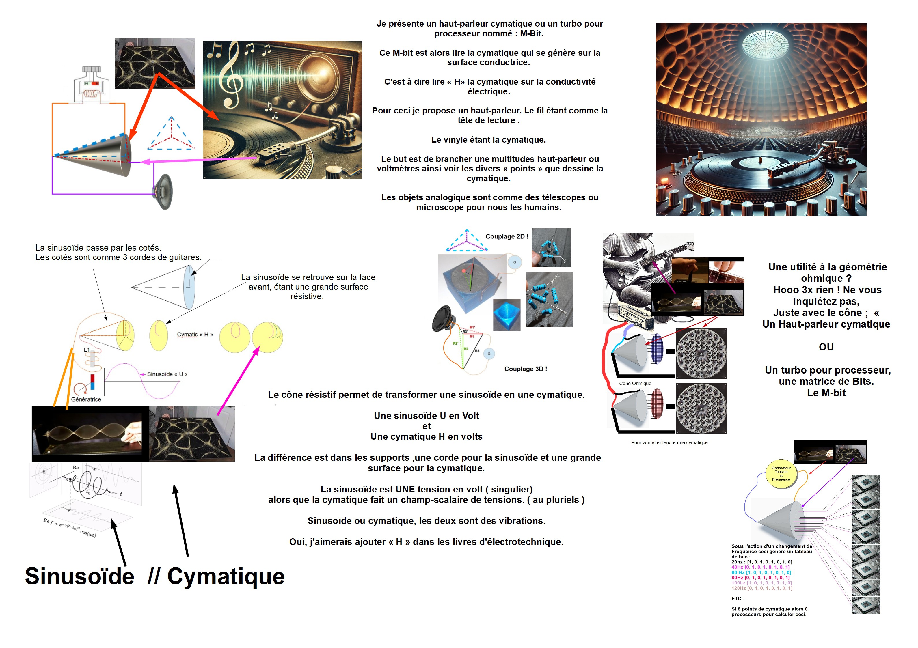
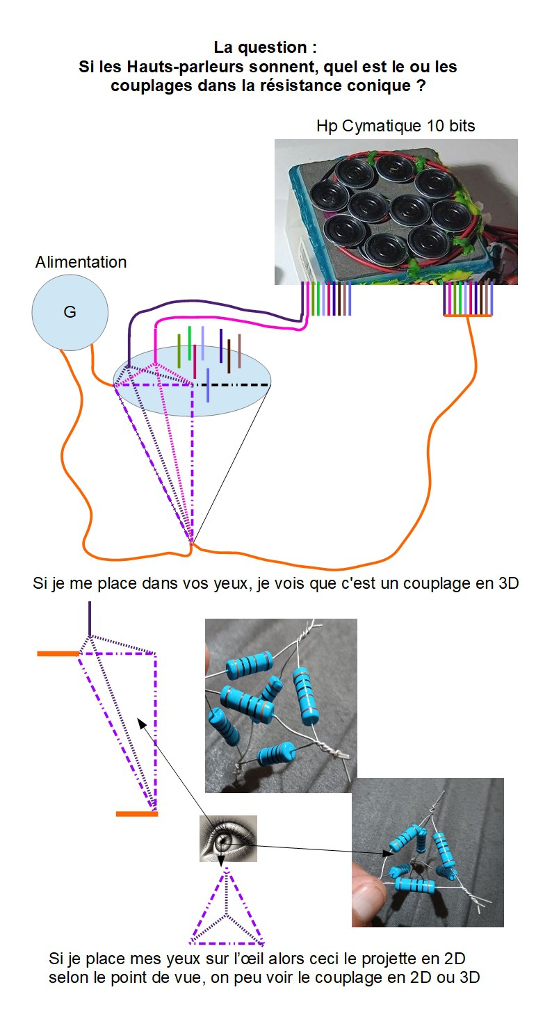
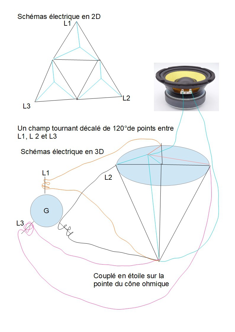
Experiment C: Electric Cymatics and Resistive Cone
Experiment C explores electric cymatics using a resistive cone, where sinusoidal vibrations translate into observable waves at the base of the cone. The goal is to visualize and hear the cymatics through loudspeakers. This principle mimics an acoustic cymatic table but applied to electrical resistance.

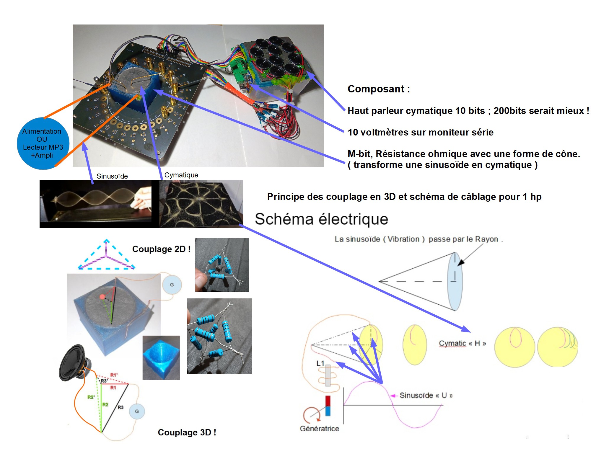


Experiment D: The Zanode - Nesting of cones
Experiment D combines the results of experiments B and C with two nested resistive cones. The aim is to study a potential...


Looking forward to faradaic capacitance and henric inductance too. 🤣