 Nathaniel VerLee
-
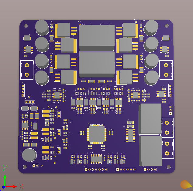
Update on next PCB design
08/28/2014 at 02:53 • 0 commentsI have been pushing forward with the next PCB design where all elements of the system are combined on one board. I have included a screen capture of what the board will eventually look like. You can clearly see the two inductors for each phase of the buck boost power stage, surrounded by 4 Buck FETs on the left and 4 Boost FETs on the right. I am hoping to push this design out to get fabbed next week. Then I will be focusing back on writing code, getting some delrin laser cut to mount this in a pelican case with a battery, and building up a BOM for a parts order.
![]()
-
Video Posted
08/21/2014 at 01:33 • 0 commentsHere is an overview video of my project for the Hackaday prize entry:
-
MPPT working!
08/19/2014 at 02:54 • 0 commentsI managed to get my MPPT algorithm up an working this weekend. It was very neat to see the converter searching through the solar panels V-I curve by changing the duty cycle - the algorithm runs slow enough right now that you can watch it happening on the scope, with the edges of the FET gate drive jumping back and forth:
![]()
I also re built the base all the boards were attached to over the weekend, it now has sensors on both the input and output of the power stage. Its a lot nicer and neater looking than the previous base:
![]()
I had plenty of time and some moderate sun to test in, so I was able to shoot some footage of everything in action. I am editing it this evening and tomorrow will post it to make all the requirements for the hackaday prize!
-
MPPT Algorithm work
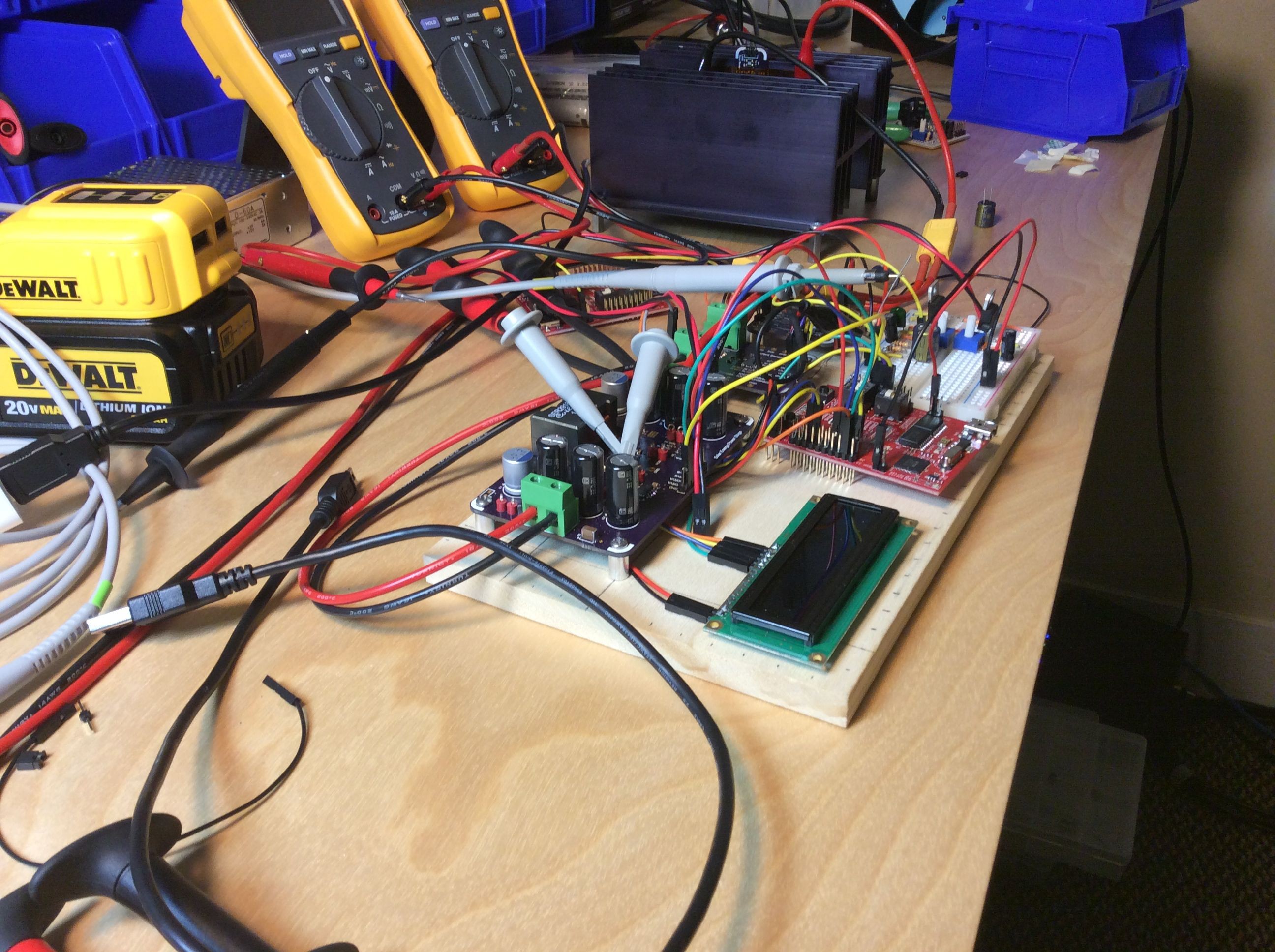
08/14/2014 at 03:26 • 0 commentsI have been working on getting an MPPT algorithm up and running on my current test setup, which currently looks like a complete mess:
![]()
You can see the converter stage, display, microcontroller, a current and voltage sensor board, and a breadboard with supply rails all mounted to a lovely piece of poplar. The big heatsink in the background has a large 4 ohm load resistor for testing the converter stage.
My current efforts are focused on getting MPPT up and working. A typical MPPT algorithm working something like this: http://low-powerdesign.com/article_CYsolar_071311.html You can see in the Algorithm flowchart that it makes its decisions about how to change the duty cycle of the converter based on both power change and voltage change. Since the voltage of the DC supply voltage remains constant, its kind of a toss up if the voltage increases or decreases - its really just noise at that point. The current algorithm ends up making silly decisions and never finds the max power point of the DC supply. It actually is possible to find the MPP of a DC supply like this, since the supply will go into constant current limiting at some point - I would just need a dramatically different algorithm. I do want to be able to charge batteries from both a panel as well as a general DC voltage source, but instead of making an algorithm that will draw more and more power until it trips the DC supply's overcurrent protection, I will just make an option to input how much power the converter may draw from the source and tell the system what kind of source it is drawing from.
I have decided that I really need to do two things to move forward:
1) figure out how well my voltage and current measurements actually are (and if they are very noisy, is it just the ADC or the sensors themselves). This will help in determining how big of a duty cycle step size needs to be made when searching for the MPP.
2) Test the system out on a sunny day with a real solar panel (since I dont have a solar panel simulator) to see if my algorihm actually works.
Hoping to get a video done as well this weekend, and also create a short PDF on the specs, design goals, current state of schematics, etc.
-
Current and Voltage Measurement now working
08/06/2014 at 12:15 • 0 commentsI have managed to get the current to readout properly as well, this was pretty strait forward to get it to display sometime, less so to get it to display a correct current. There is an interesting issue with bringing power up and down on this TI MCU - when I power down the digital supply but leave the analog reference and ground connected, it draws a huge amount of current. I have rectified this issue by adding a 1K resistor in series with the 3V reference supply. Next it will be fairly strait forward to implement a simple MPPT algorithm once I find a sample rate that gives me nice stable ADC values each time I take a measurement. I plan on displaying the Power and battery current on the display for now, and later add charge statuses when I start working on the battery charging algorithm.
-
Getting good voltage measurements
07/23/2014 at 03:49 • 0 comments![]() I had historically been having issues getting stable and accurate voltage measurements. A scope on the 3.3V supply rail revealed a pretty noisy rail, probably due to the digital core chugging along at 60MHz. The ADC supposedly has some sort of internal bandgap reference, but since I switched to an external 3.0V linear regulator as the ADC reference I have had much better measurements. The voltage sensor board has two ranges: a 30V range and a 60V range. Currently I am using the 30V range and with the new voltage reference I have been getting very good readings. Next step is to work on measuring current, and the caluclinting power.
I had historically been having issues getting stable and accurate voltage measurements. A scope on the 3.3V supply rail revealed a pretty noisy rail, probably due to the digital core chugging along at 60MHz. The ADC supposedly has some sort of internal bandgap reference, but since I switched to an external 3.0V linear regulator as the ADC reference I have had much better measurements. The voltage sensor board has two ranges: a 30V range and a 60V range. Currently I am using the 30V range and with the new voltage reference I have been getting very good readings. Next step is to work on measuring current, and the caluclinting power.
Solar Energy Generator
A solar energy system up to 500W in power for use with lithium batteries.


 I had historically been having issues getting stable and accurate voltage measurements. A scope on the 3.3V supply rail revealed a pretty noisy rail, probably due to the digital core chugging along at 60MHz. The ADC supposedly has some sort of internal bandgap reference, but since I switched to an external 3.0V linear regulator as the ADC reference I have had much better measurements. The voltage sensor board has two ranges: a 30V range and a 60V range. Currently I am using the 30V range and with the new voltage reference I have been getting very good readings. Next step is to work on measuring current, and the caluclinting power.