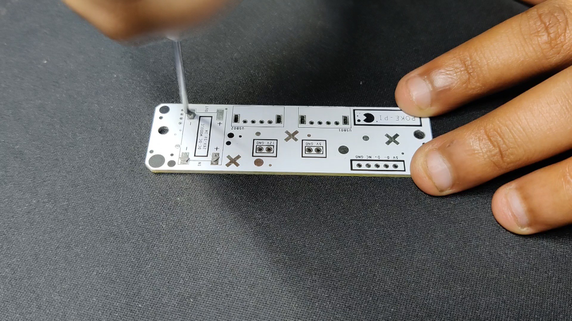
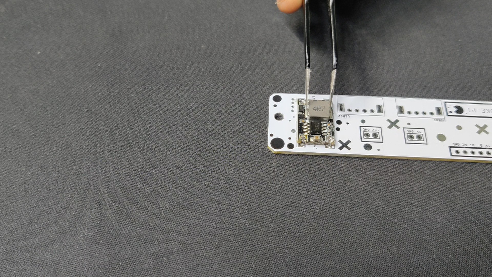
Using a solder paste dispensing needle, we first add solder paste to each component pad, one by one.
Next, we pick and place all the SMD components in their places on the PCB using an ESD tweezer.
With extreme caution, we lifted the complete circuit board and placed it on the SMT hotplate, which increases the PCB's temperature to the point at which the solder paste melts and all of the components are connected to their pads
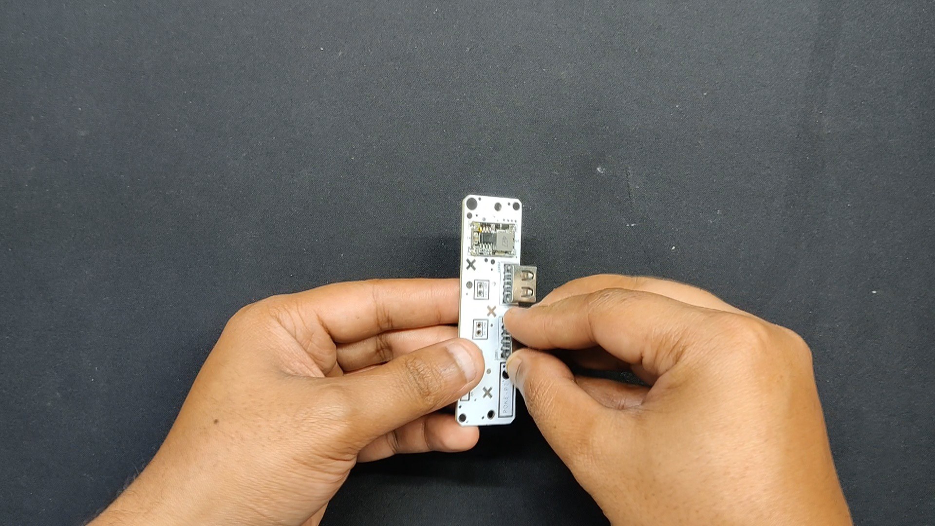
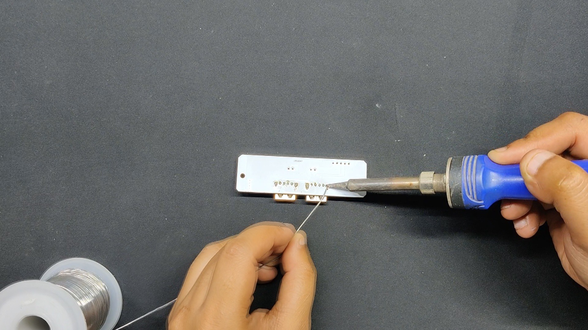
Next, we added the THT components, which included the two USB ports, and soldered their pads using a soldering iron.
2
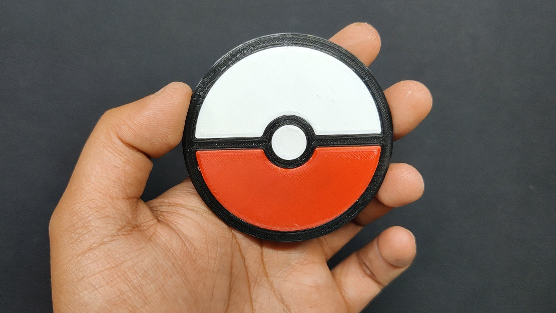
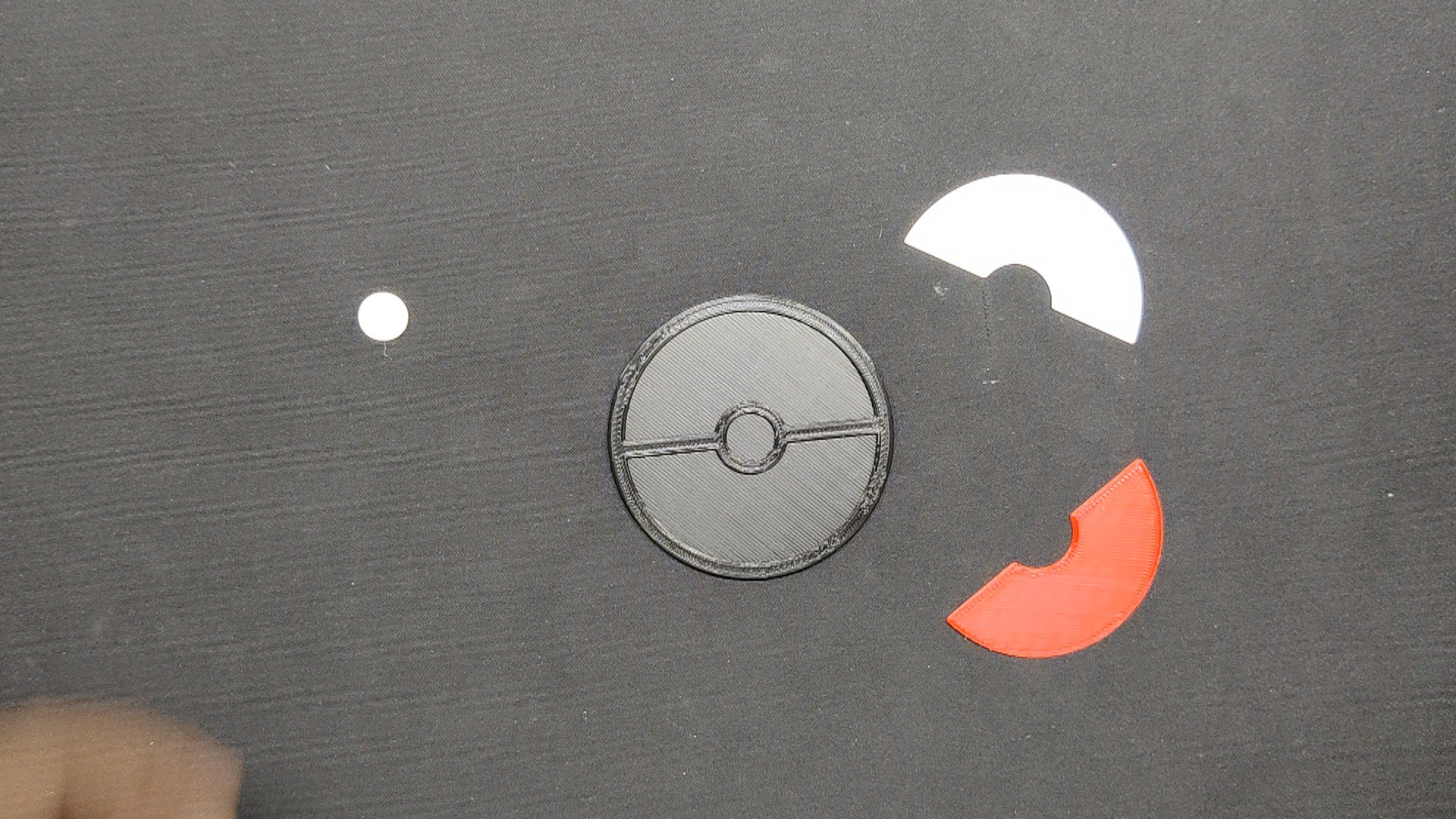
Pokémon Logo Assembly
The black pokeball base component is initially assembled, which includes the white center piece, the red bottom area of the pokeball in the lower section, and the white part on the upper section of the pokeball.
Here, we have made the part with very low tolerance, so they fit perfectly in place.
3
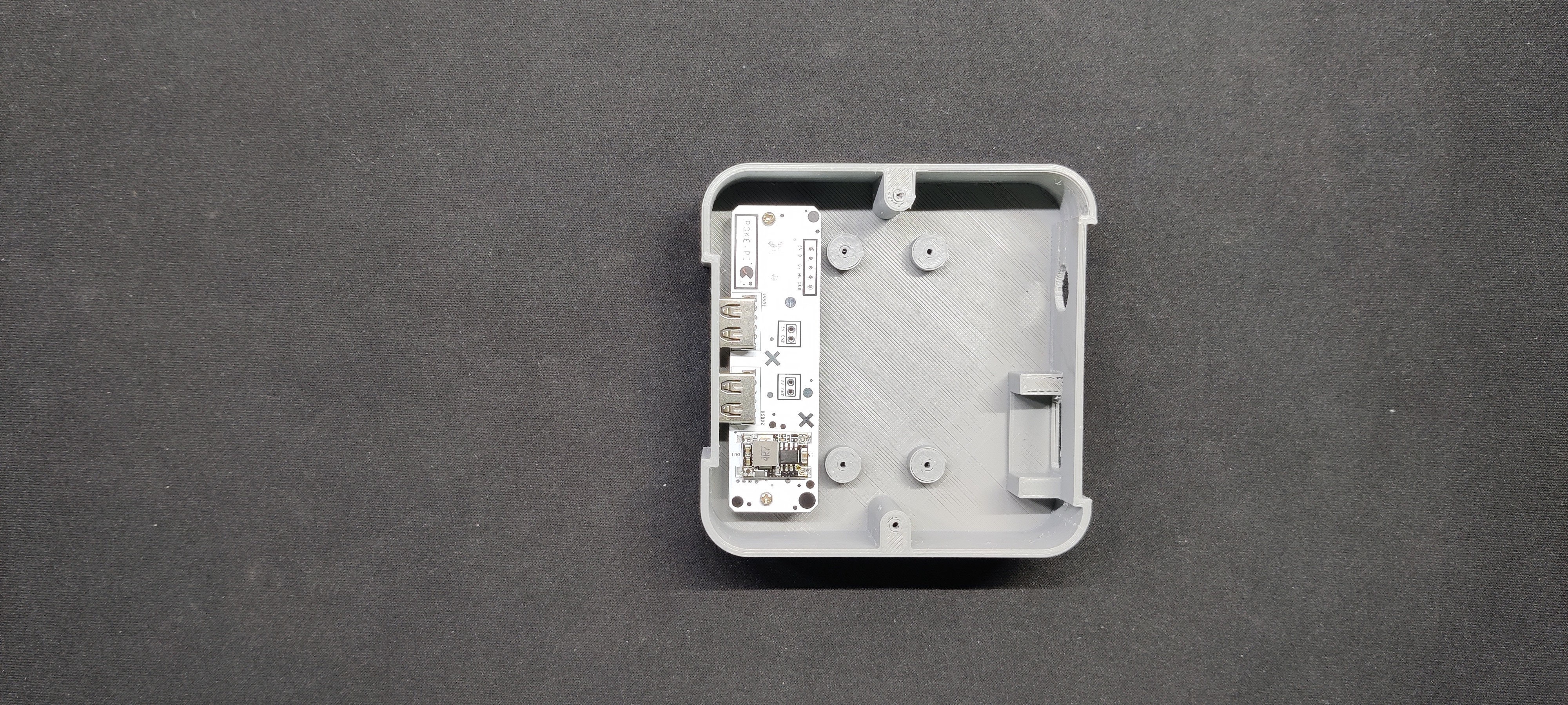
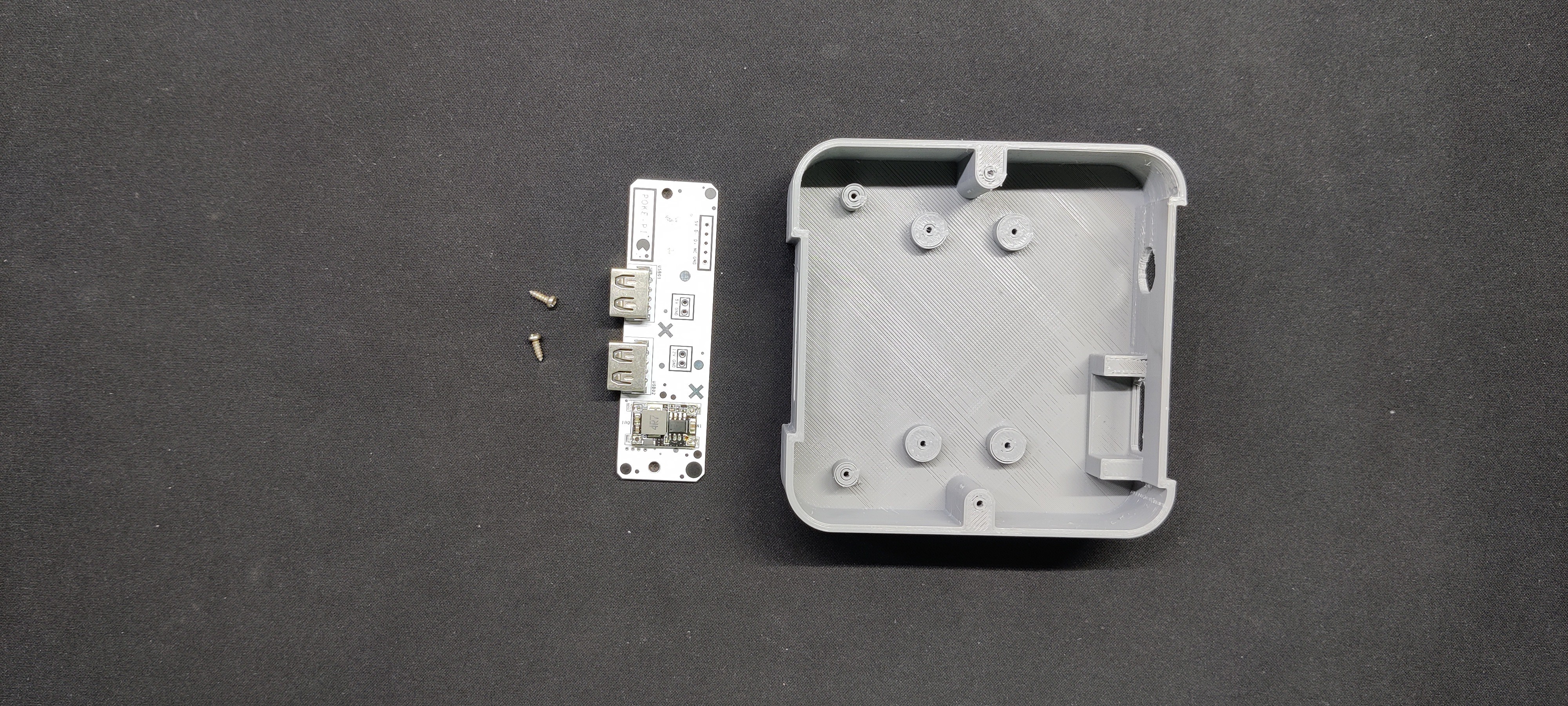
Base-USB Breakout board Assembly
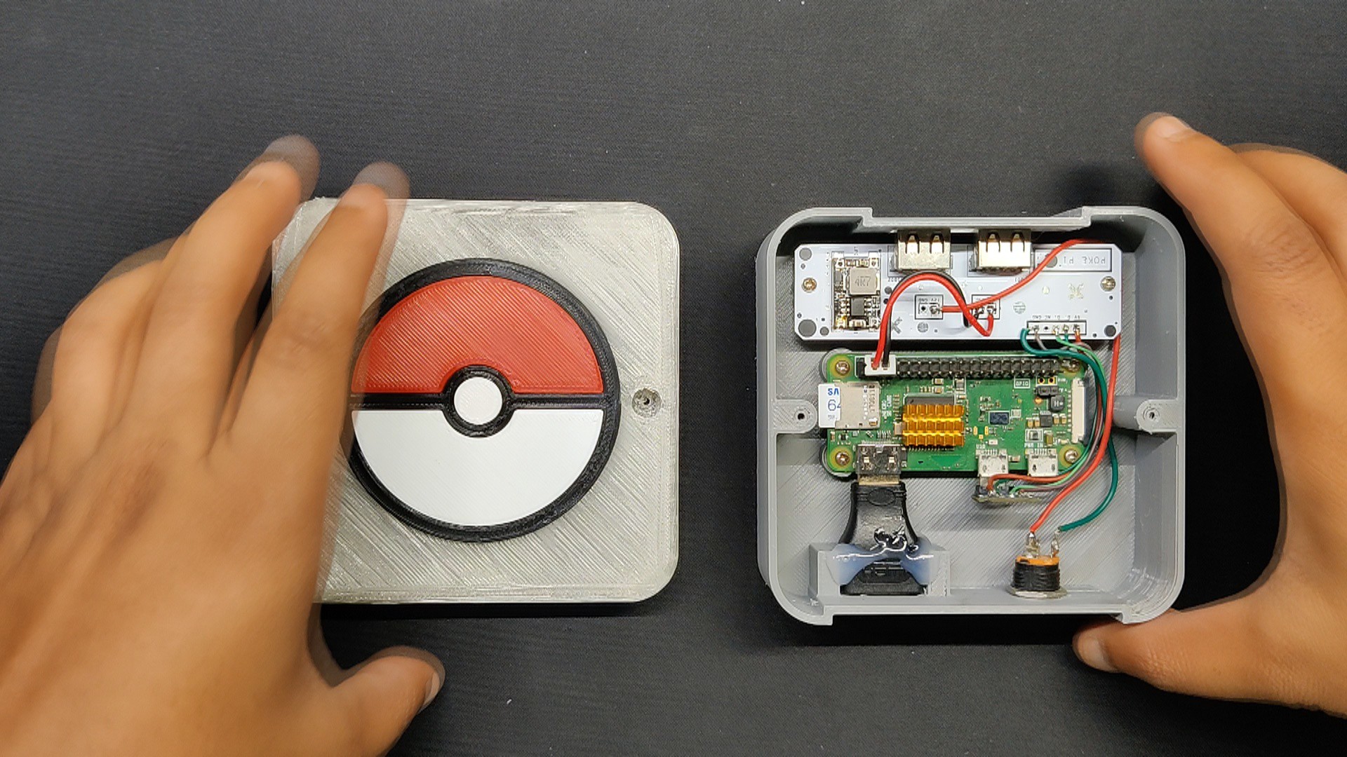
We started the base assembly process by placing the USB breakout board inside the main body and securing it in place using two M2 screws.
4
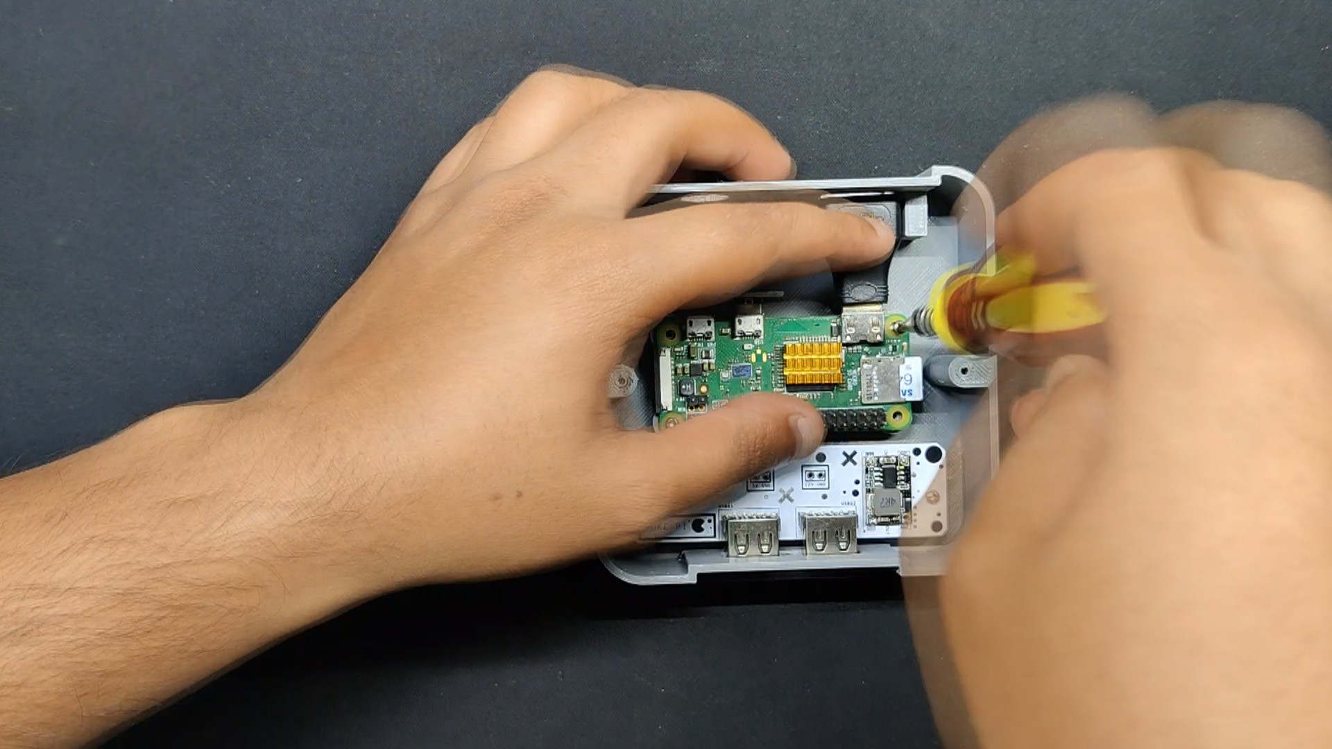
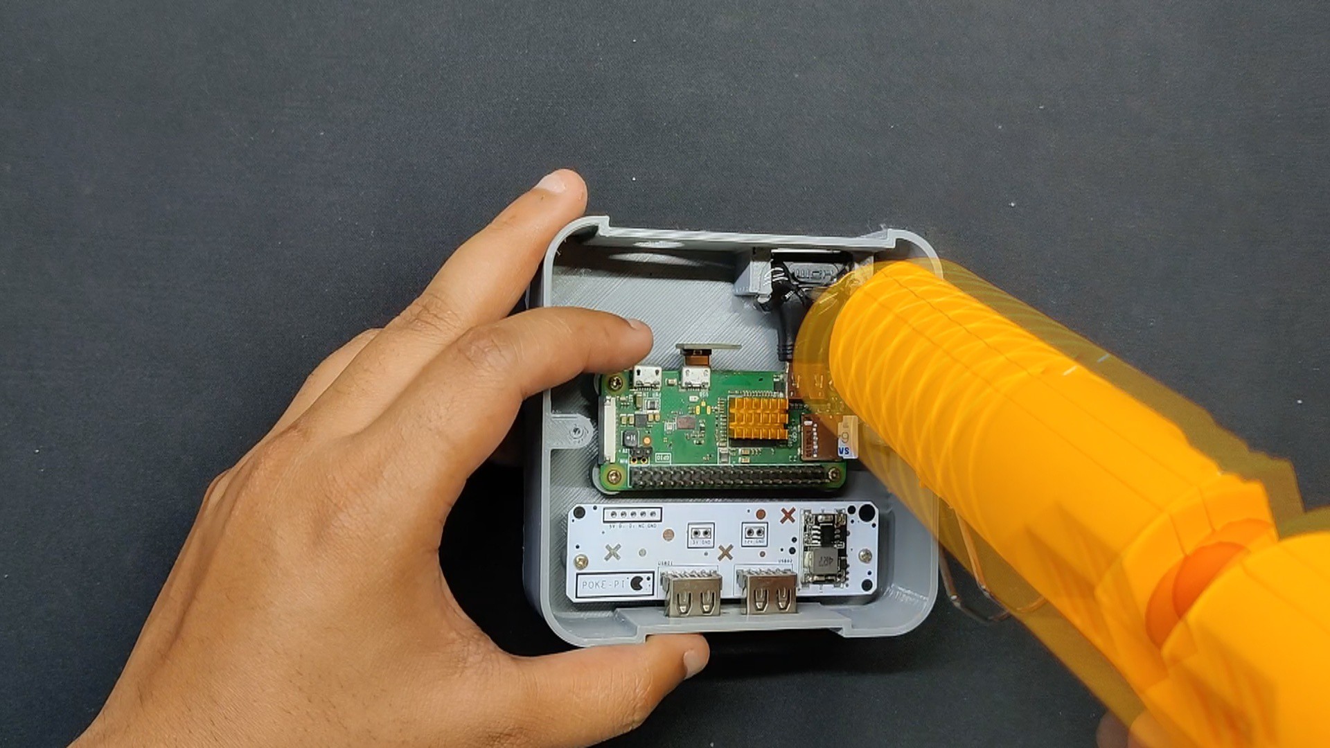
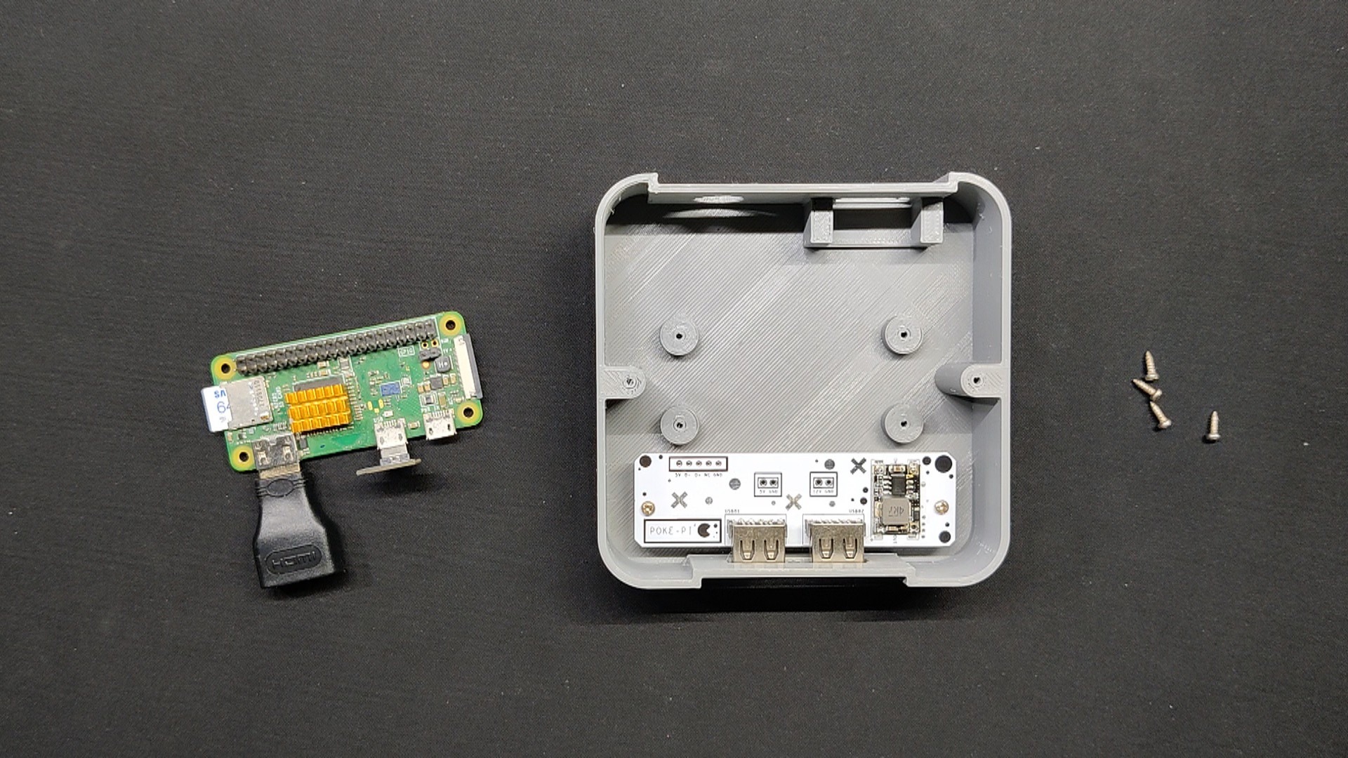
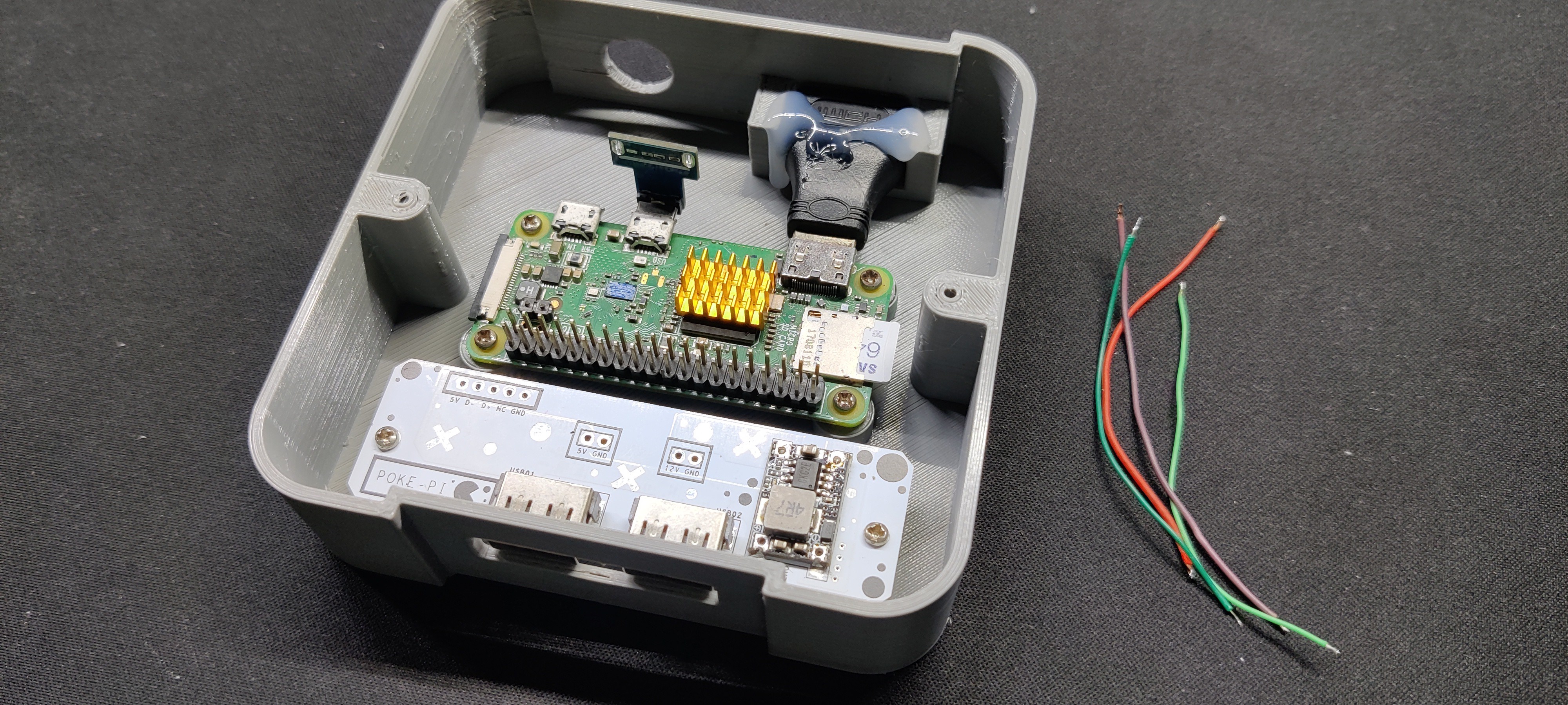
Raspberry Pi Zero: Base Assembly
Raspberry Pi Zero is added in its place; we use four M2 screws to secure the Pi Zero with four screw bosses modeled on the body.
We see that the HDMI adaptor flexes a little after the Pi Zero is secured; this movement could lead to wear and tear on the PI Zero's micro HDMI port when the HDMI cable is plugged in and out. We use hotglue to secure the adaptor in place in order to fix this.
5
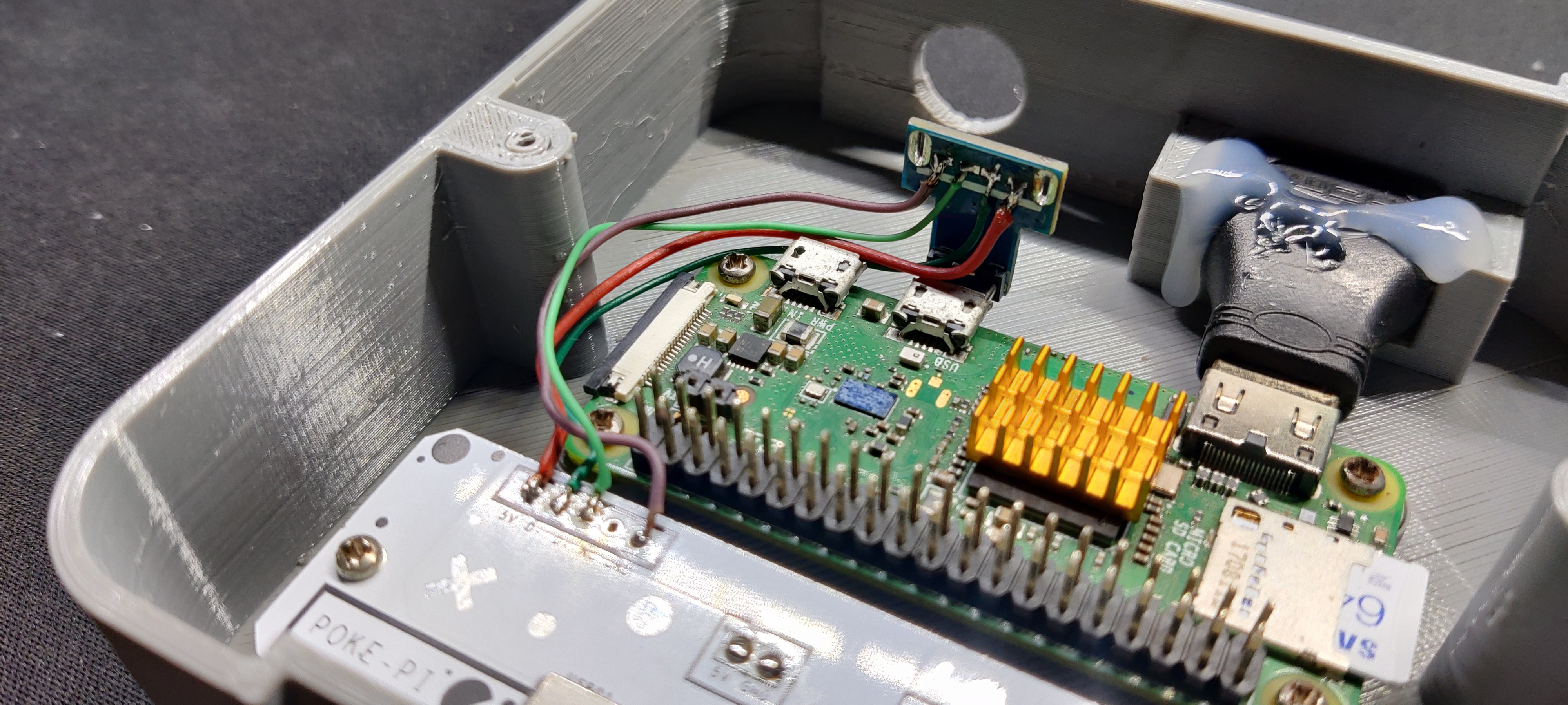
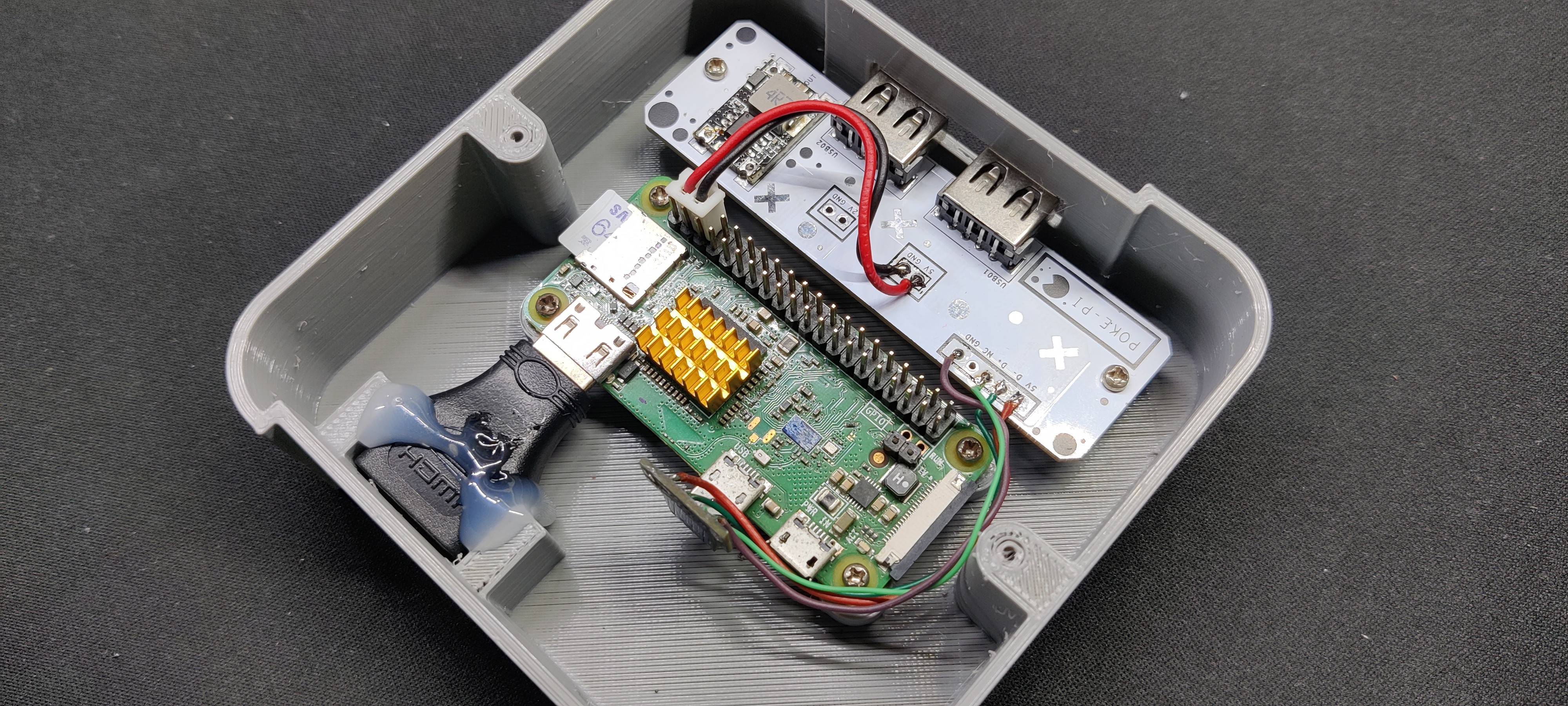
Wiring Process
The initial step in the wiring process is to connect the Pi Zero's USB OTG breakout to the CON5 terminal of the USB Board.
We linked the USB OTG breakout's VCC to the USB Board's VCC, as well as GND to GND, D-to-D-, and D+ to D+.
Next, we connected the positive and negative terminals of a JST UC2515 wire harness to the USB breakout board's 5V output connector.
To supply Pi Power, we hook the JST connector onto the GPIO pins 5V and GND of the PI Zero.
6
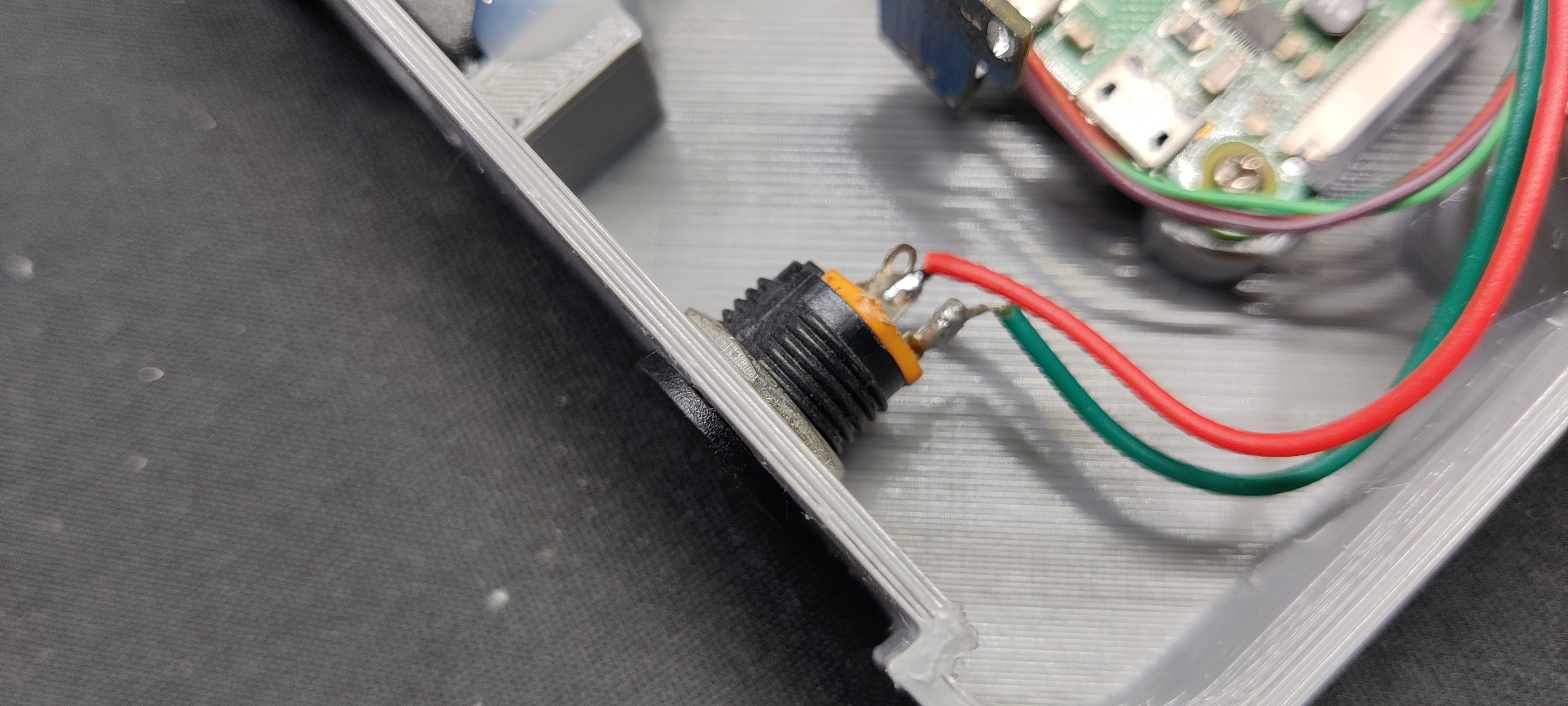
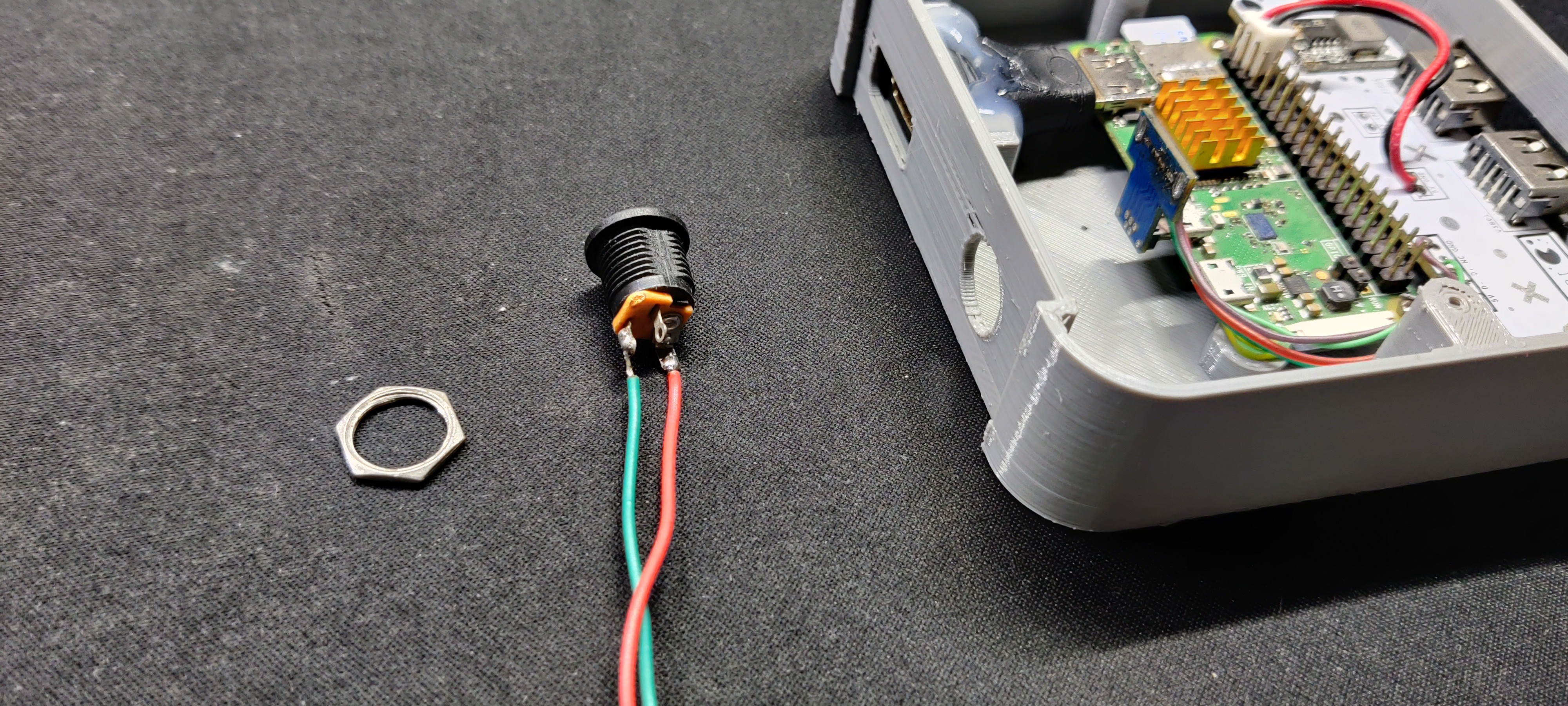
DC Jack Assembly
Next, we install the Barrel DC jack on the back side of the main body and then connect its positive and negative terminals with the USB Board's 12V and GND terminals.
We will be using a 12V power adaptor to supply 5V to Pi Zero.
7
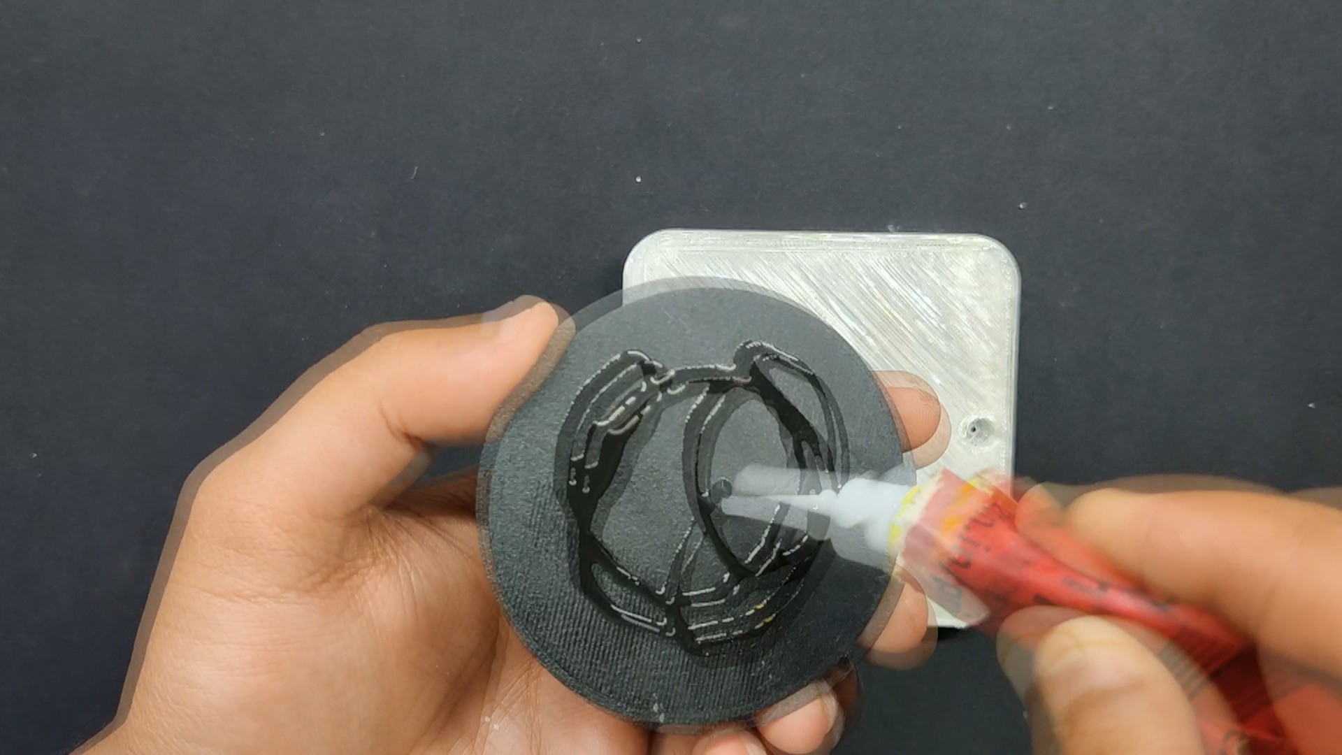
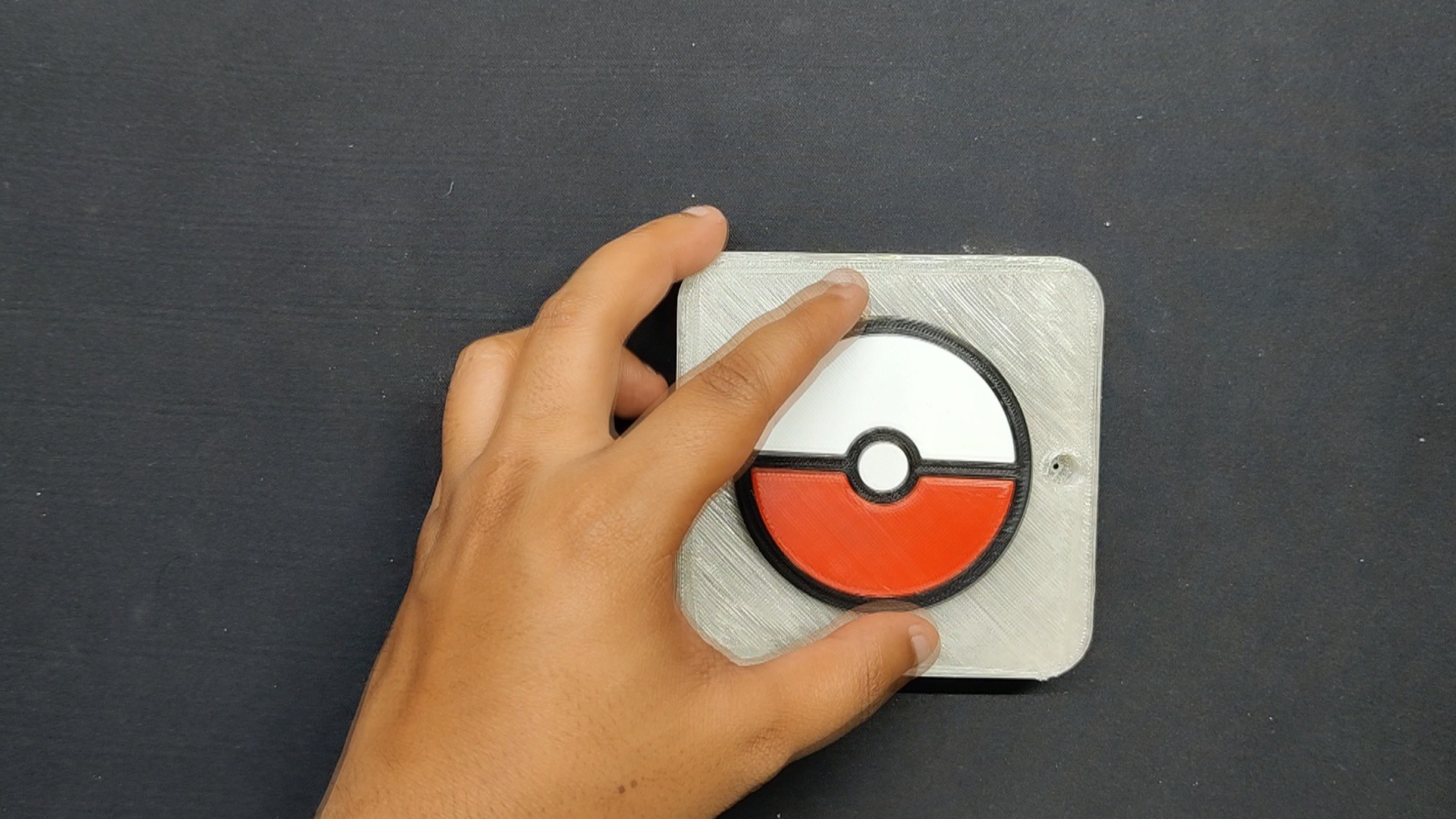
Top Lid Assembly
We applied super glue to back side of the Pokeball Logo and added the Logo on top of the Lid Part
8
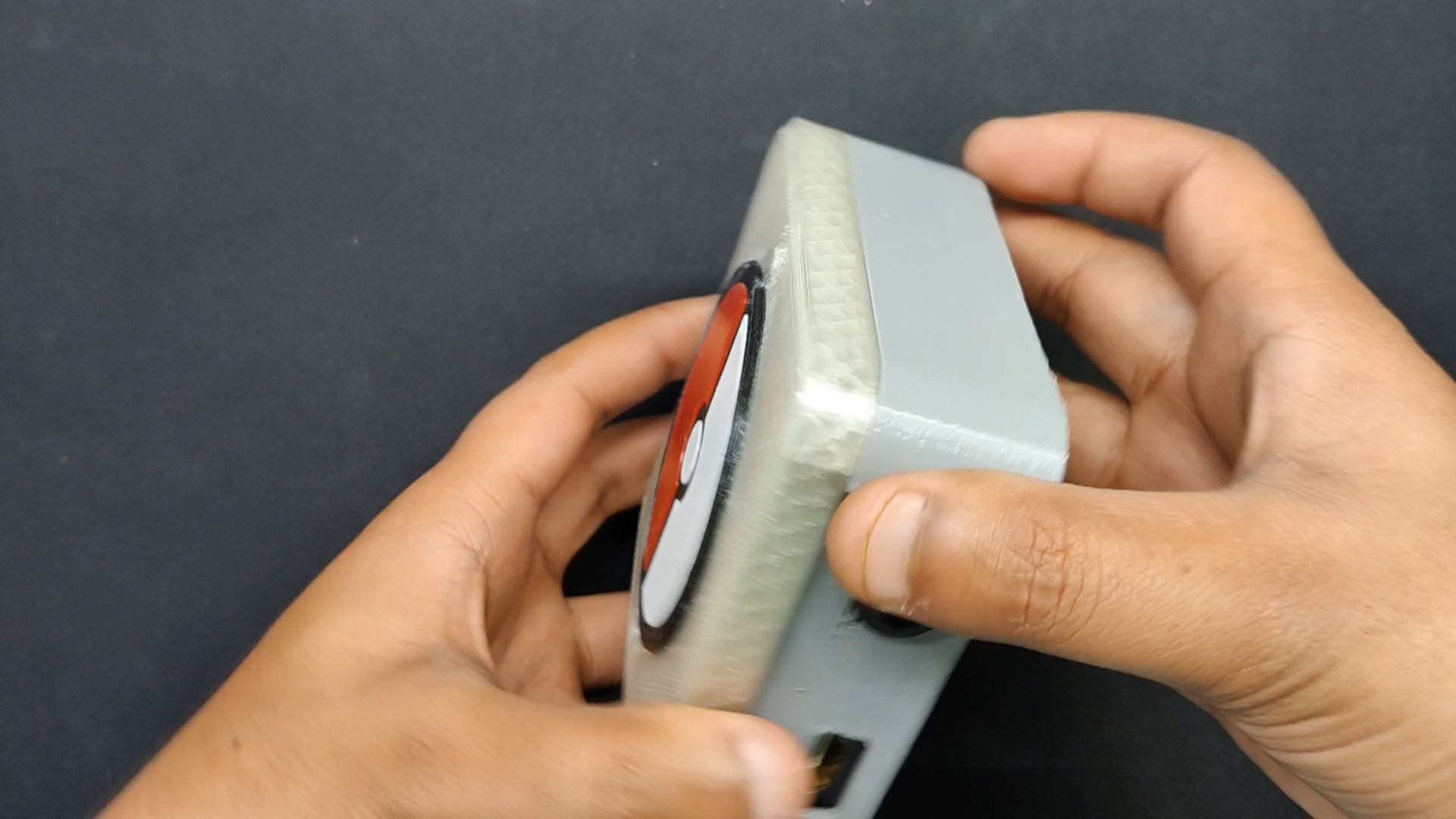
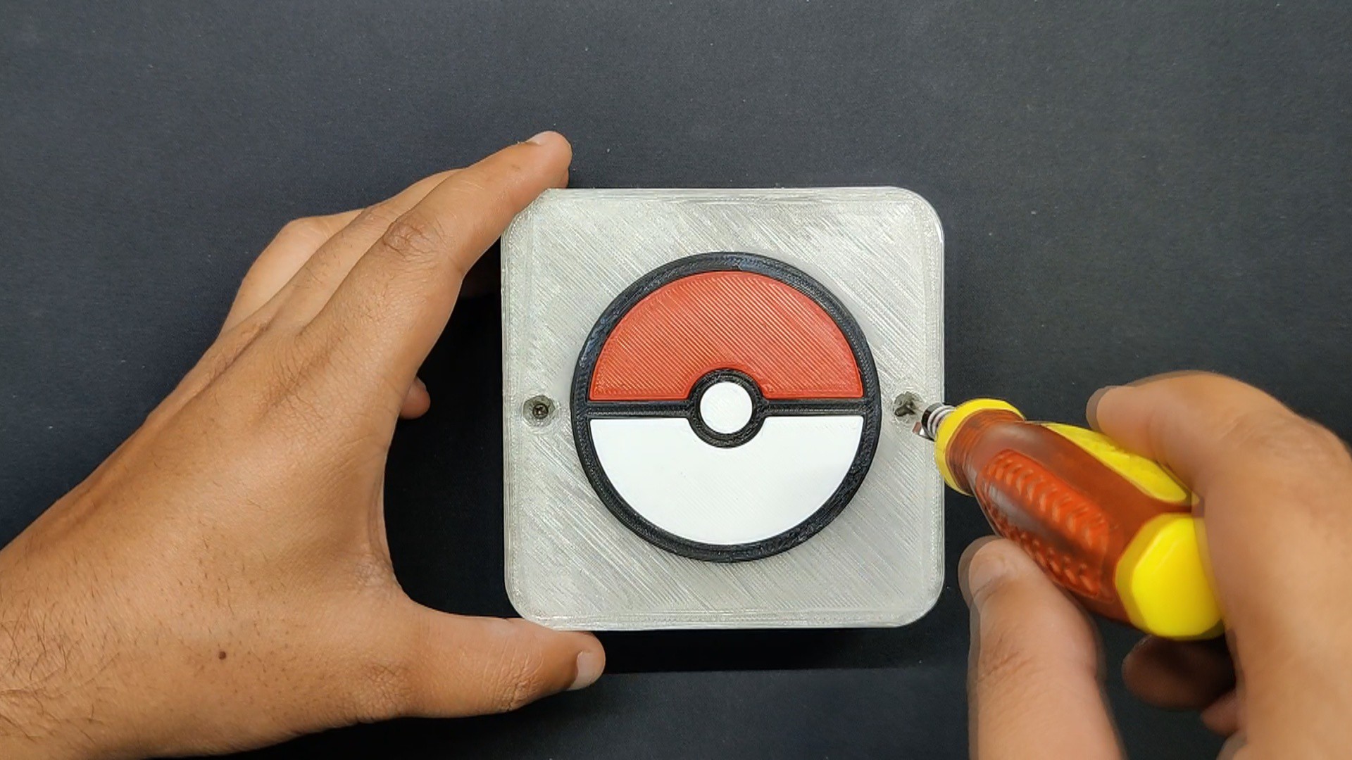
Final Assembly Process
We slid the lid in place on top of the main body.
Two screw bosses have been added to the main body, and two M2 screws are used to fasten the lid to the main body via these screw bosses.
9
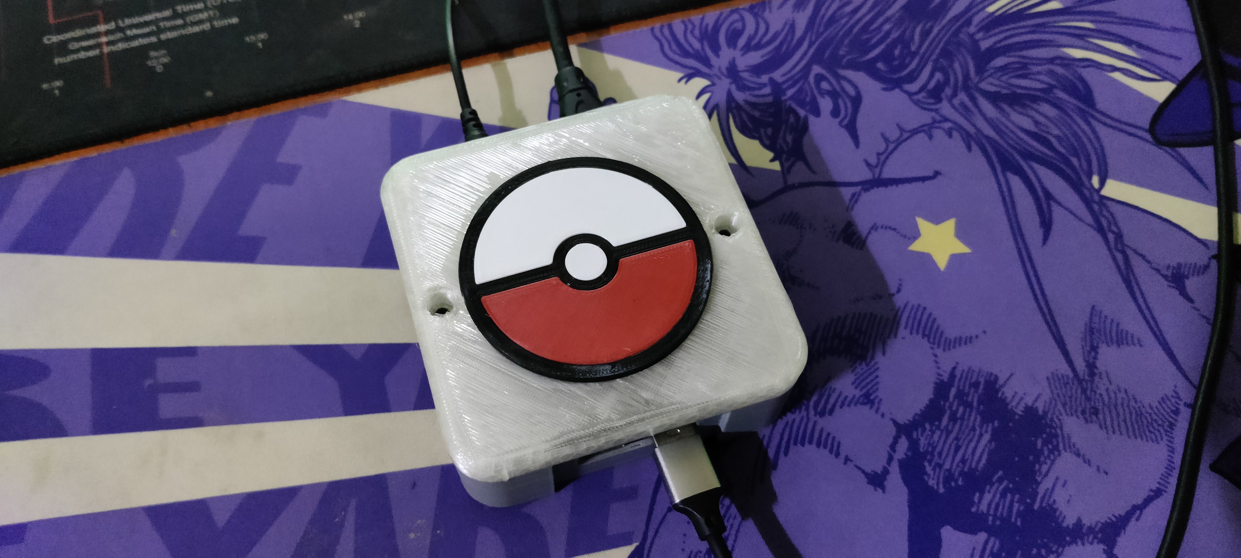
Result
Here is the end result of this little build: a completely functional, portable gaming console with a Pokemon theme. Here, a Pi Zero Snuggly is securely mounted inside the enclosure. On the front side, there are two USB ports where users may connect one or more controllers. On the rear, there is an HDMI connector for connecting an external monitor and a DC barrel jack for supplying 12V power.
10
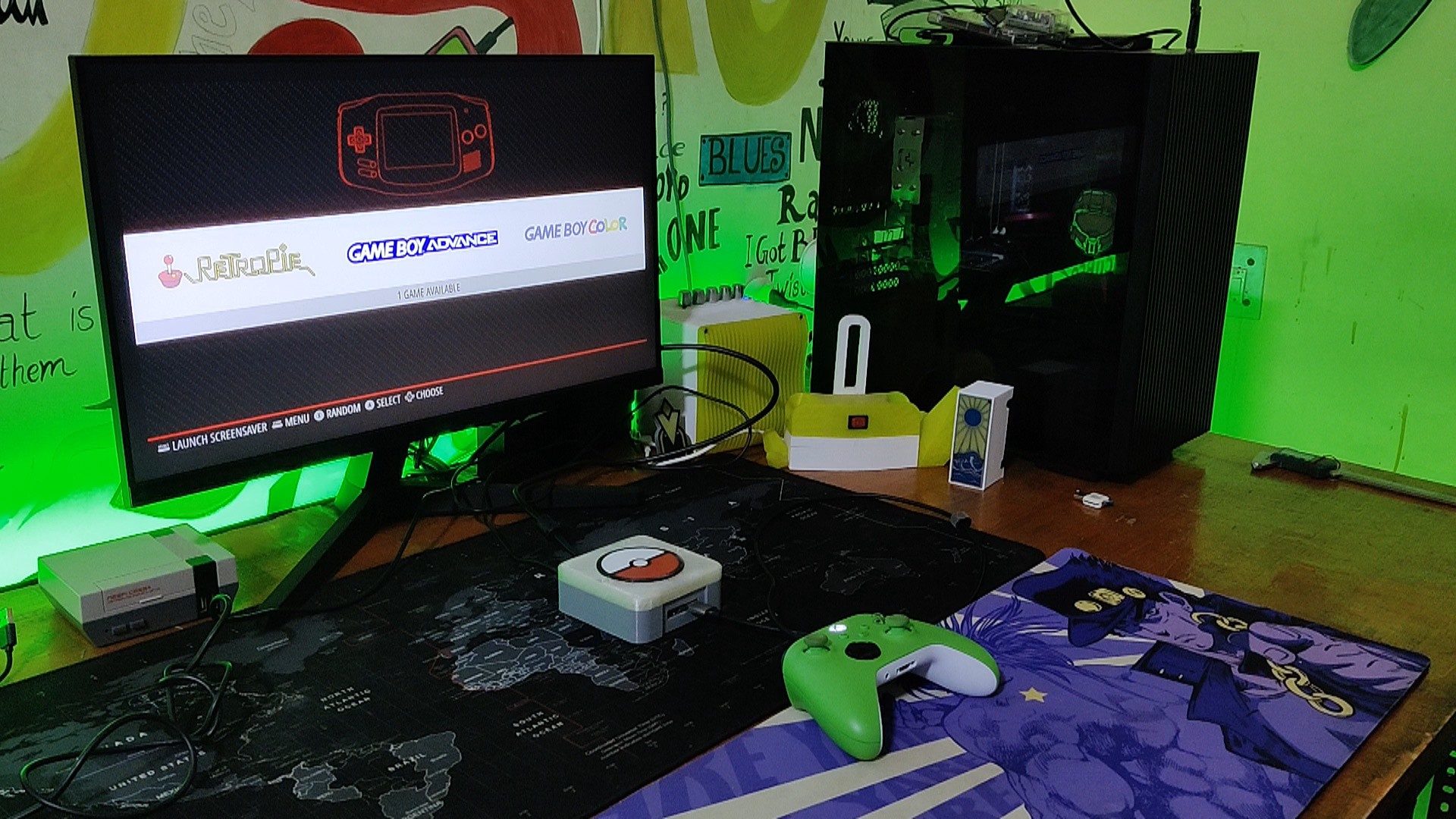
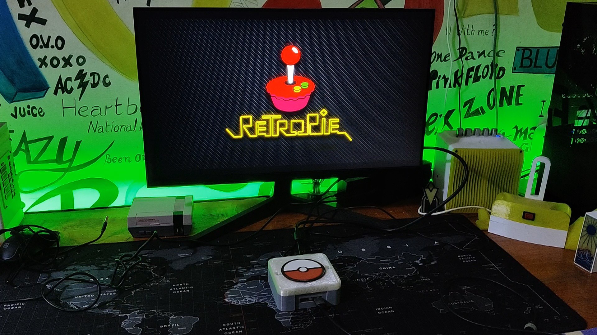
RetroPie: Setting Up
Here, we are utilizing RetroPie, a well-known open-source OS that lets you transform a single-board computer, like the Raspberry Pi, into a retro game console. Enjoy old games from systems such as the NES, SNES, Sega Genesis, PlayStation, and many more. It is made to simulate a broad variety of retro gaming devices and platforms.
It's worth noting that while RetroPie itself is legal, the legality of downloading and using ROMs (game files) from copyrighted systems is a gray area and may vary depending on your country's laws. It is essential to ensure you have the right to use the game files before adding them to your RetroPie system.
We begin by connecting a 64 GB microSD card to a computer using an SD Card Reader.
Retropie can be manually installed by downloading the ISO file from their website, or it can be installed using Raspberry Pi Imager, which is by far the best method for doing so.
Here, we download and set up the Raspberry Pi Imager.
The SD card is then inserted into the microSD card converter, which is then connected to the PC.
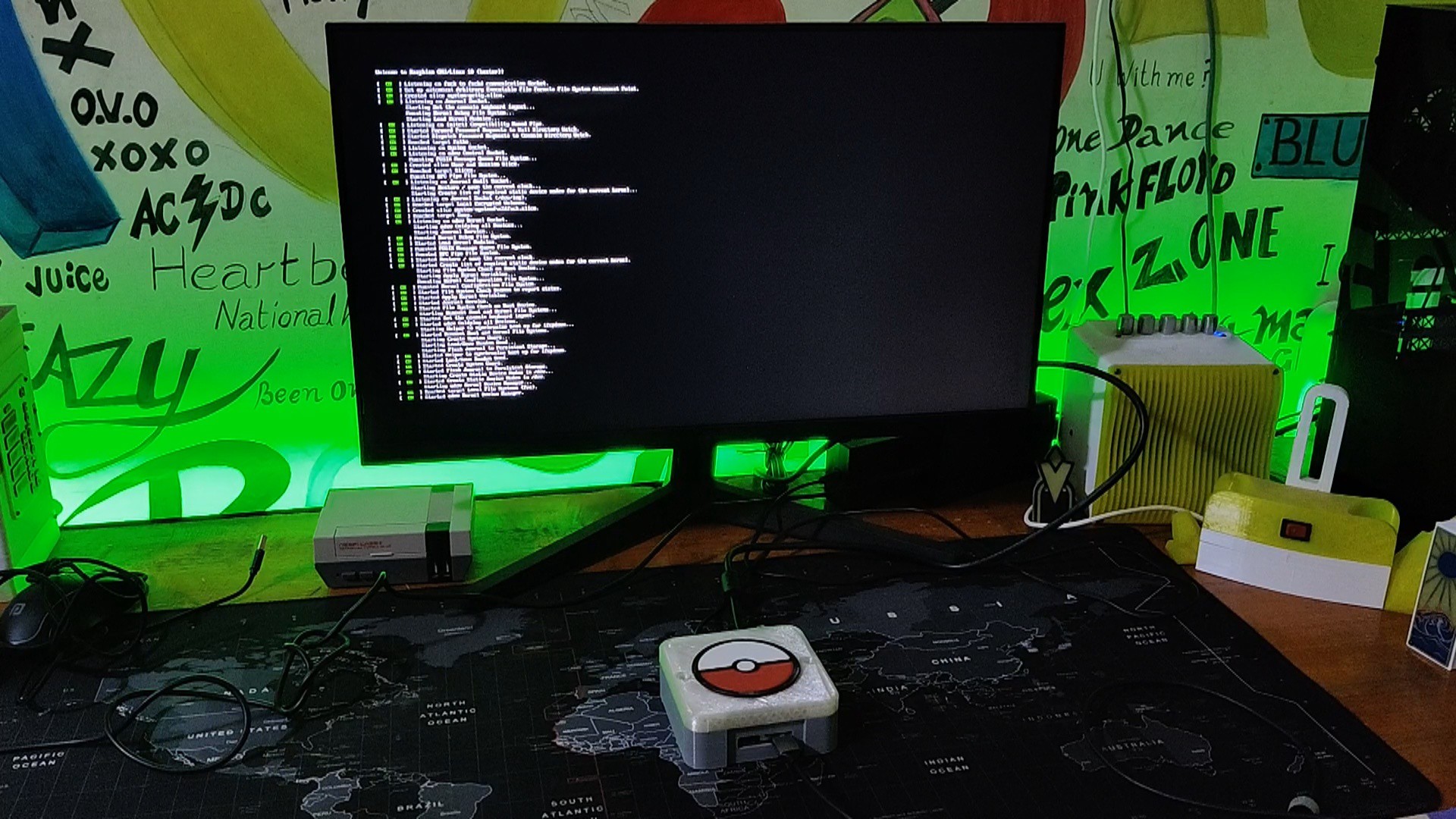
The welcome screen will appear on the first boot, followed by the process of mapping gamepad keys. After mapping the controller, we arrive at Retropie's home screen, where a list of all the consoles is displayed.
For adding games, we first use a blank pendrive, flash drive, or HDD and create a folder named "RetroPie."
We added the pendrive into the Raspberry Pi USB port, and the pendrive will start to blink, indicating that the computer is creating folders on the drive. After the blinking stops, we can unplug the pendrive.
We attach the pendrive to the computer once more and access the retropie/roms folder, where we can see all the console's folders. Finally, we paste the rom into the correct console folder.
As soon as we connect the pendrive to the Raspberry Pi, it begins blinking once more, indicating that the ROMs are being copied into the Pi. Depending on the size of the ROM, this procedure can often take between two minutes and two hours. Once the copying is complete, the pendrive will stop blinking, allowing us to remove it.
The Pi will be restarted after the ROMs have been copied into it, and the game list will then be updated.
There's a well-documented wiki made by Raspberry Pi about this process and other steps of using Retropie, which you can checkout at the below link.
 Arnov Sharma
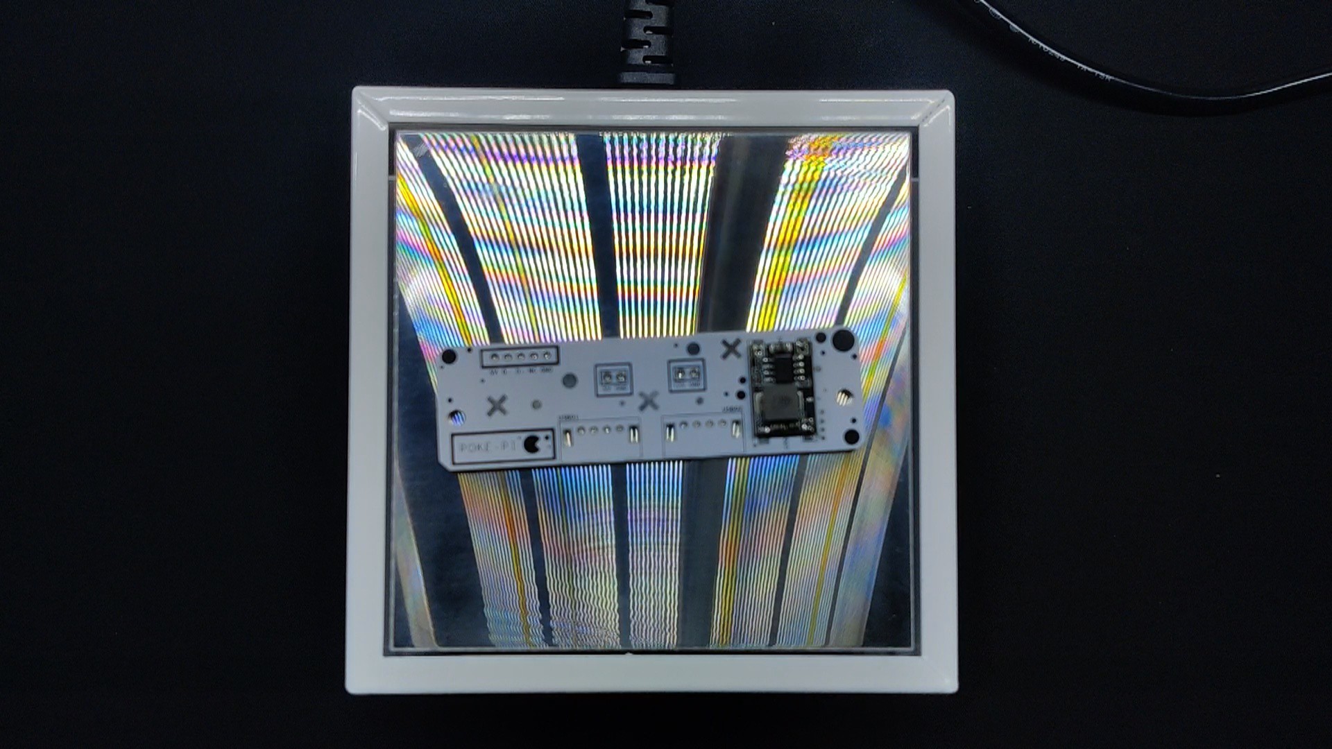
Discussions
Become a Hackaday.io Member
Create an account to leave a comment. Already have an account? Log In.