-
1Gather parts
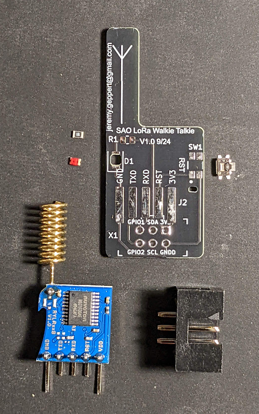
Gather PCB, SMD Led, SMD resistor, SMD button and male SAO connector.
![]()
-
2Prep the pads
DISCLAIMER: I do not have the proper equipment or skills for this surface mount non-sense but I did my best with that I have. I apologize for hack job you will see in the instructional photos. I ordered a finer tip for my soldering pencil which will hopefully help.
Flux and tin the LED, Resistor and Button pads.
![]()
-
3More flux and install
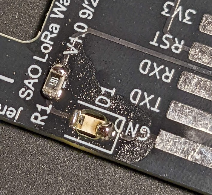
Flux the tinned pads and install each component with your favorite tweezers and magnification device. Note the polarity on the LED. The negative side towards the bottom of the board. Conveniently it is near the Lora module pads labeled GND.
The LED doesn't need to be perfectly level in the cutout. Just get solder to bridge the connections and call it good. It is very hard to see if it's aligned perfectly when installed.
For the resistor, use the tweezer and carefully press down on it while you heat the edges over the tinned pads. It should plop down in. Again, it doesn't need to look pretty to work.
![]()
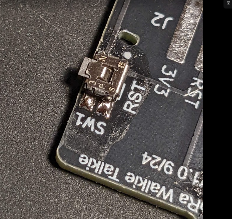
Follow the same technique for the switch.
![]()
-
4Optional Lora Module Step 1
Flux and tin the pads for the Reyax Lora module.
You will need to clip the middle 3 stock leads on Lora module. Align with the board to see where to clip the leads. Leave the outer 2 leads long. These will get "clamped" under the Male SAO connection you'll add at the end.
![]()
-
5Test and Clean
Use a continuity tester to verify that depressing the PTT/Reset button completes the circuit between the RST pad and GND points.
Use a 3.3 VDC power source on the 3V3 and GNND pads to verify the LED works.
Clean up the flux mess with isopropyl alcohol at this step. You are going to be covering up access to the components you installed with the Lora if you choose to add that.
-
6Optional Lora Module Step 2
You will be covering up access to the previously installed components with this step. Make sure they work and are cleaned up.
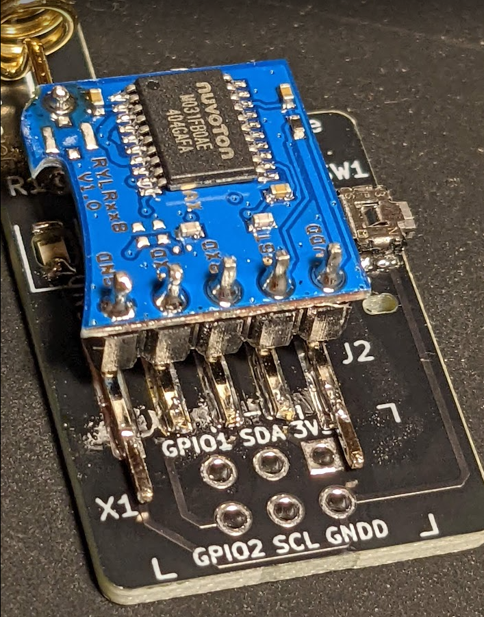
Flux and Tin the PCB pads and the Lora module pins on the side that will face the board. Then carefully align the module with the PCB pads and work your way across the pins with heat. They should squash down pretty easy. Massage it and add solder as you see fit. The SAO connector will clamp those outer pins so it only needs to be a solid electrical connection and not so much mechanical.
![]()
![]()
-
7Add SAO connector
Install the Male 6 pin SAO connector on the back side or optionally just use standard header pins.
-
8Done!
Enjoy the radio bling on your favorite badge or SAO display or add Lora communication via serial communication on GPIO1 and GPIO2 pins to whatever you plug it into.
![]()
 jeremy.geppert


Discussions
Become a Hackaday.io Member
Create an account to leave a comment. Already have an account? Log In.
Great project! Next time you solder SMD parts, just place a bit of solder on one pad, hit everything with flux, then hold the part in place with your tweezers, heat up that pad so the part lays flat- now you can add solder to the rest of the pads and you're good.
Starting with solder on more than one pad makes it so much harder- unless you plan to heat the entire thing, which is not good unless you have an oven/hotplate/etc...
Are you sure? yes | no
Thanks! Can confirm that is the right way. I learned this after about the 10th one.
Are you sure? yes | no