-
Ready.
10/30/2024 at 02:19 • 0 commentsI just finished the batch of SOAs that do not have a Lora module installed. By the end I managed to come up with a decent technique that the SMD parts were not an issue. I AM glad there were not more than 30 of these to assemble. These are now ready to find homes on badges!
![]()
-
Tested and Ready
10/26/2024 at 16:36 • 0 commentsAfter a neck and eye fatiguing morning session I have 10 units working, configured, labeled and tested! The rest are going to just have the LED and Button but can easily have a Lora module installed. As just badge bling they still have some merit.
![]()
![]()
-
Production Time
10/26/2024 at 13:05 • 0 commentsWith all the necessary components on my desk I am assembling 30 of these to bring to SuperCon. I ordered another 10 Reyax Lora modules so that I'll have a bunch ready to add communication capabilities to badges for whatever shenanigans people think of.
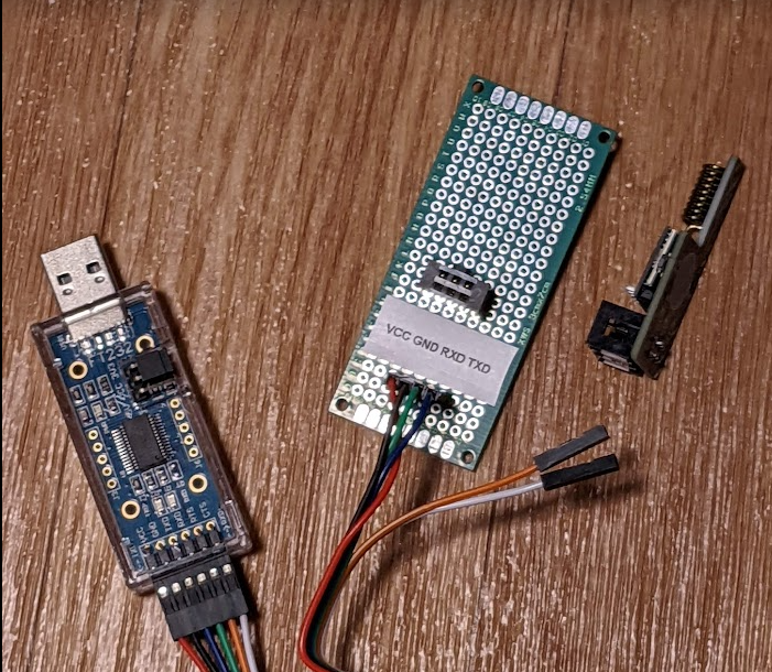
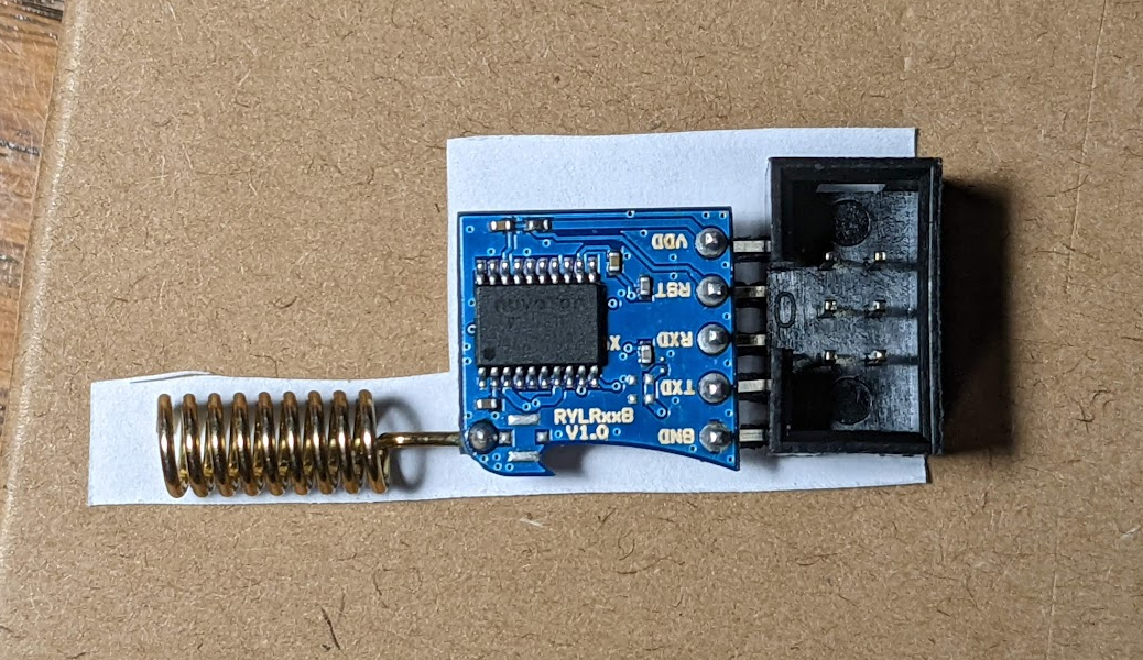
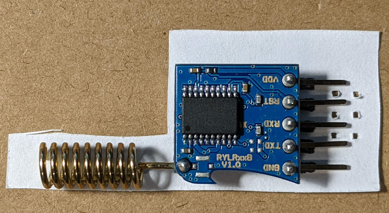
These Lora modules are configured with serial commands via whatever terminal. There is a Network ID and Address that needs to be configured so modules can talk to each other. I cobbled together a little board to make this easier to connect to a USB to Serial adapter for quick configuration.
![]()
![]()
I am setting each unit to communicate at 9600 baud with a Network ID of "8". (SuperCon 8) Then, each unit I am bringing will have a sequential Address starting with "1" and labeled as such for easy reference.
-
It's Alive!
10/08/2024 at 01:27 • 0 commentsThe boards showed up early today! Woohoo! No big mistakes on this one and the two I populated work!
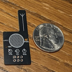
They are small and no bigger than necessary. (US Quarter on right)
![]()
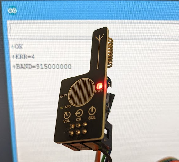
Reyax RYLR998 Lora module installed on the back and some AT commands sent to make sure all the pins mapped correct. Note the antenna is well protected.
![]()
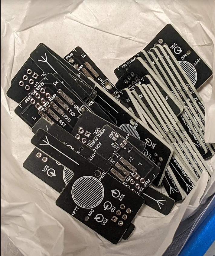
Pile of boards in the highly anticipated blue box.
![]()
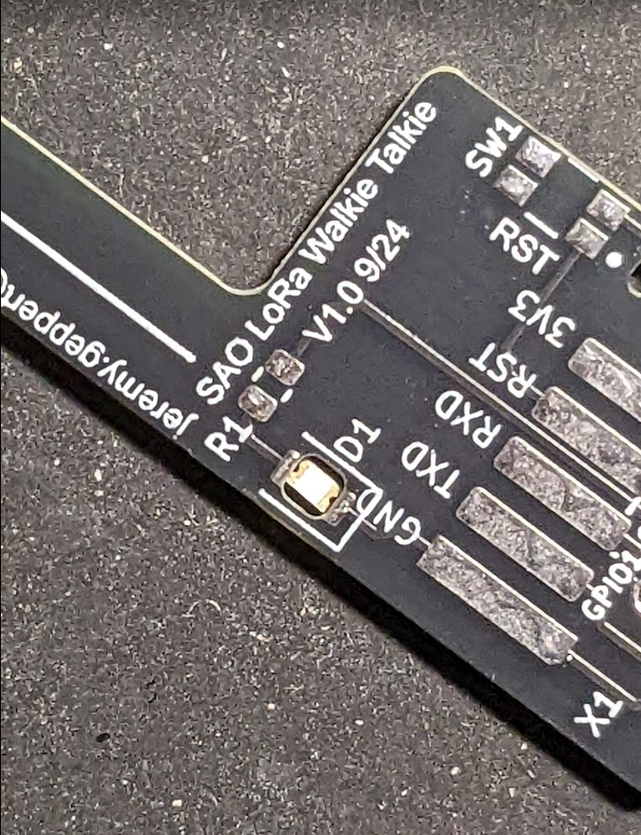
The only "issue" is that the hole for the LED is a bit too big. Either it got milled bigger than it should or I really missed math class. The SMD led was supposed to hang on the edges of the hole. Fortunately, I am good a solder bridges (especially where not needed) so I was able to make this work just fine. Being slightly recessed in the board is kind of cool. I am not sure how I feel about soldering 28 more of these yet.
I quick note on these SMD parts. Wow... don't drop them on the floor. That took awhile to find.
![]()
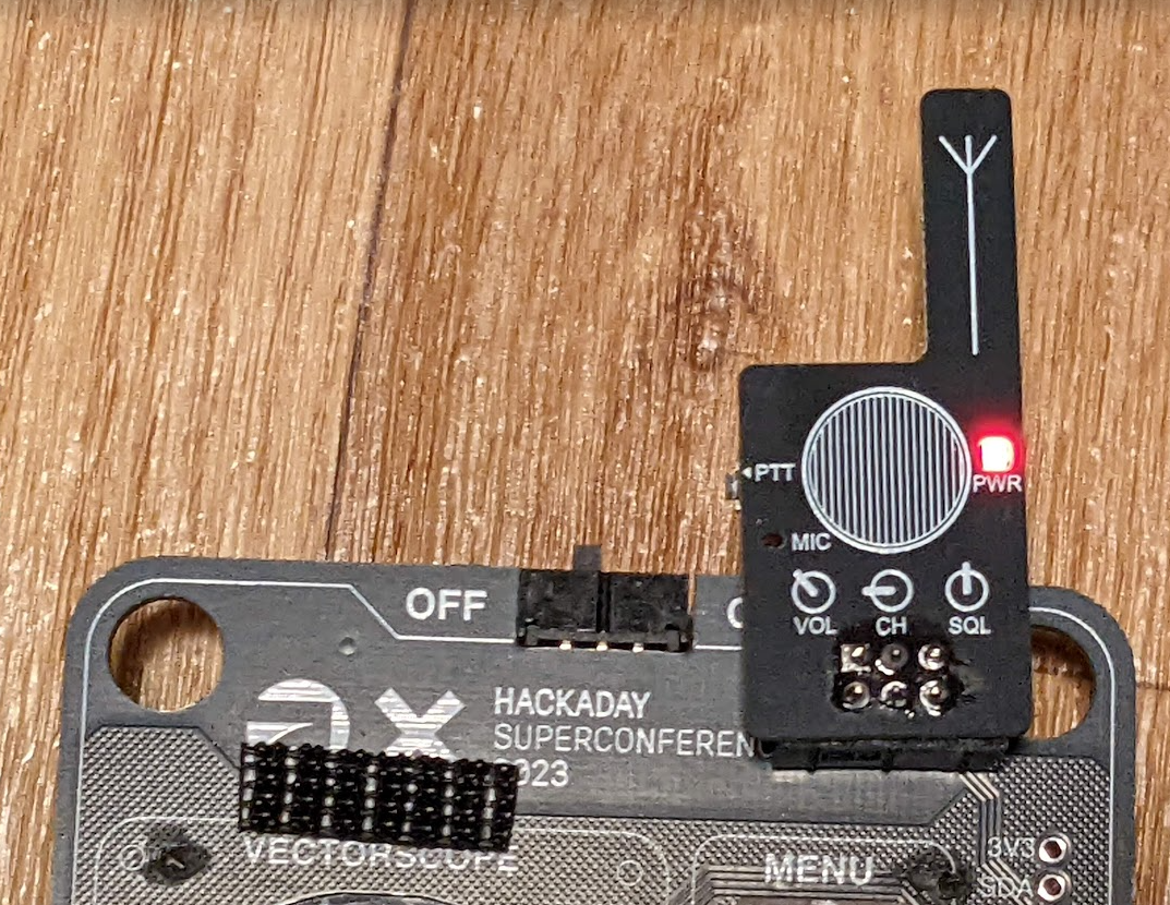
My brother Andy estimated that 180 ohms would be about right for brightness. He was right and it gives the effect I was hoping for. The "PTT" button on the left is actually the reset button for the Lora module. This is necessary once powered depending on how you are connecting to it. I am pleased that the button also fills an aesthetic role.
These are intended to be "blingy" SAOs even without the Lora Module on the back. The modules are around $12 from most sources. It's a bit too much $$ to put one on each SAO unfortunately. I plan to bring a few with me that have Lora modules on them to play with and maybe loan out for shenanigans and experimenting with at SuperCon 24'.
![]()
-
Boards are on the way
10/05/2024 at 13:16 • 0 commentsThe boards are set to arrive on Tuesday!
-
Parts starting to arrive
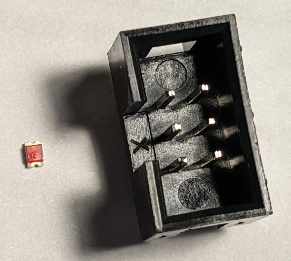
10/02/2024 at 17:39 • 0 commentsThe resistors and leds showed up from DigiKey today. SMALL!!!! I am going to reverse mount this LED through a hole in the board for the power light. This will be interesting. The boards are delayed due to the Chinese holiday but I hope to have them by the end of next week.
CMD17-21VRD/TR8 LED on the left next to SAO connector on the right.
-
Lights, Revisions, Ordered boards!
09/29/2024 at 04:47 • 0 commentsAfter some help from my brother once again there is now a red power light. It's a tiny board and getting a bit crowded. I submitted an order for a bunch of boards tonight after verifying everything 10 times.
Ordering resistors and leds from DigiKey next. They are SMD, this will be fun. The through hole effect for the LED should be worth it though.
![]()
![]()
Don't worry!!! This isn't a repeat mistake like on my first SAO Speak & Spell boards... The pins on the LoRa module get trimmed and the whole thing slides down during assembly,
I found the print mirrored image in KiCad for alignment purposes when you pads are on the back of the pcb.
![]()
-
Different mounting solution and a power LED
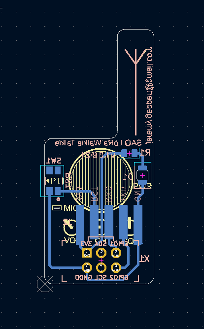
09/27/2024 at 04:43 • 0 commentsI had planned to use a right angle socket connect to plug the Reyax LoRa module into. However, when I physically prototyped this tonight I found it was going to take up too much room and push the length up to near 2". I really want to keep this board small. My brother Andy (Core64 guy) suggested removing the through holes and using SMD pads and just solder the existing right angle pins on the module to the back of the board. Yep, this is the way. I learned how to turn my footprint in KiCad into SMD pads. This added a benefit of less through holes polluting the front of the board. Happy accident.
With the planned right angle socket... too big!
![]()
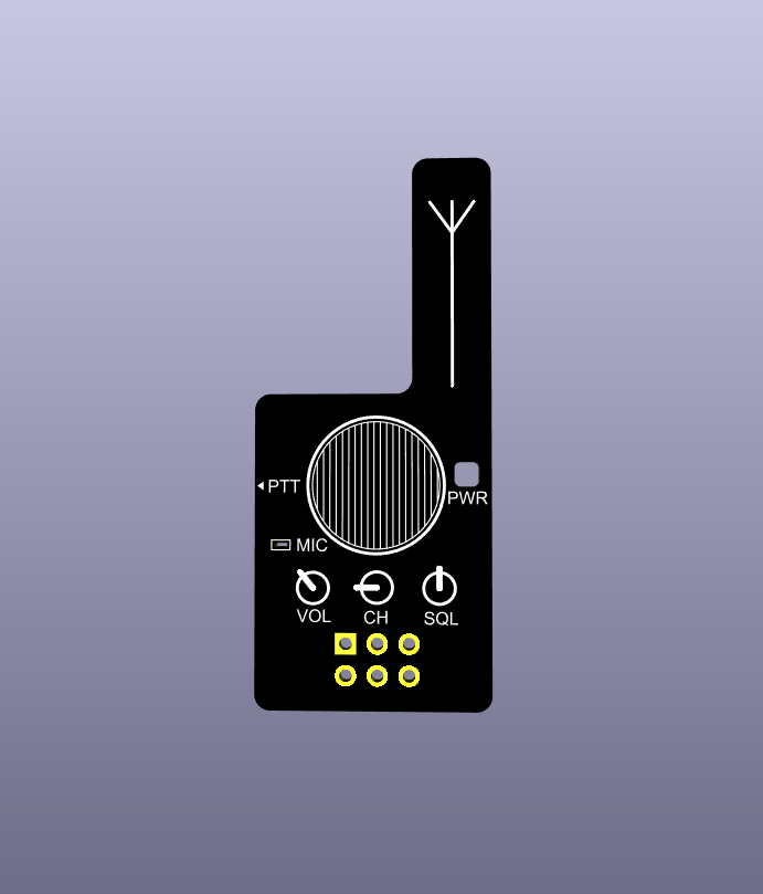
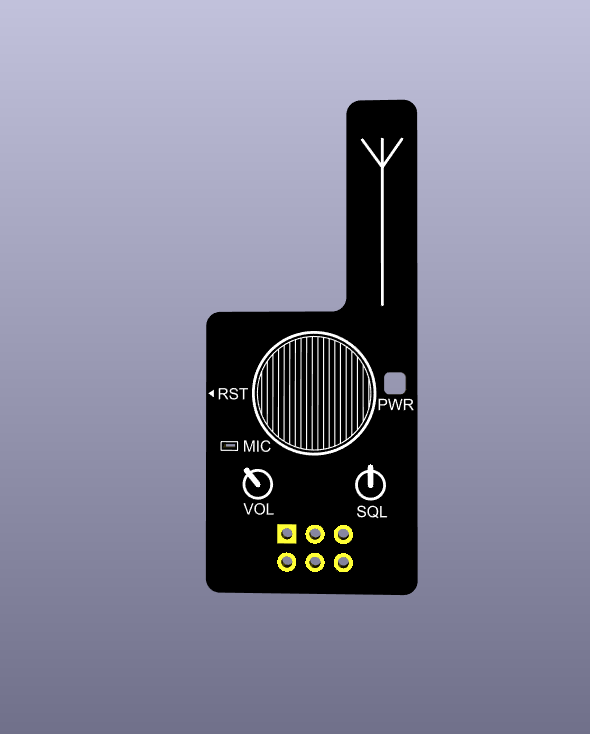
Cleaner front now in the rendering. Note: Mic label/hole is just for aesthetics, no microphone.
![]()
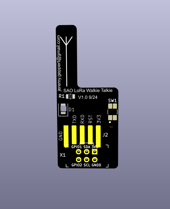
The back is getting crowded!!!! Red LED and Resistor to shine through hole in board indicating power. This will allow this SAO to be just a fun non-functional board as well.
![]()
Even this blind dog finds bones... The standoff created by the 90 degree pins on the Lora module keep the antenna off the board just enough. I'd like to show off the antenna but I think it needs the protection of the board.
![]()
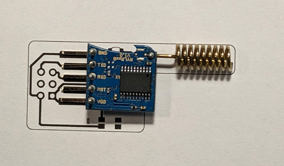
Printed out the board outline with traces to make sure things are lining up well. This will work!![]()
I'll trim the inner 3 pins but leave the outer 2 pins long and "clamp" them when installing the SAO connector. Another brother Andy suggestion. The middle pads are 6mm long and the outer are 7mm. I am hoping this is plenty of surface area to keep it anchored and durable.
![]()
-
Tedious Learning
09/26/2024 at 12:13 • 0 commentsI ended up learning the finer points of making a custom symbol and footprint in Kicad. I took the struggle bus to this class though. I modified a foot print and symbol for a right angle 0.10" spaced socket that will hold the Reyax Lora module. I wanted that to have a properly identified ground pin/pad and labels on the board in case someone decided to use a different module and for my sanity. Also, the courtyard silk screen for the footprint I started with intruded on the pads for the switch. It's all good now.
I eliminated the cutout on the antenna portion of the board. It was going to be very thin. I added a silk screen antenna symbol instead. This will provide good protection for the antenna on the LoRa module.
Last thing is to add a power LED. I'm leaning towards the trick of shining through the exposed FR4 with a surface mount LED but I haven't ruled out a traditional through hole mini LED.
-
Stay on target...
09/25/2024 at 12:11 • 0 commentsThis is my second PCB design and my first hasn't arrived yet. My brother predicted that once I got over the early learning curve of the process I'd be empowered to implement all the ideas floating around in my head. Yep. I've got a long ways to go for learning but I now know enough to be dangerous.
I'm going to attempt to not get too ambitious and end up with a project that doesn't end up happening. Get something out the door that works and then iterate. Uhg, I just summarized "agile". But unlike in the software world where agile often becomes an excuse for micromanaging meetings and ignoring the bigger picture, this approach will probably work in my little world for my tiny projects.
No tx/rx lights in V1. Just a simple power light.
 jeremy.geppert


