 Thomas Flummer
For these, I used a 3D printed jig to hold the connector and the PCB in place. It's designed with a little bit of space, to make it easy to put in the connectors and pul out the finished assembly, but it's tight enough to have the connector sit pretty straight with the board.
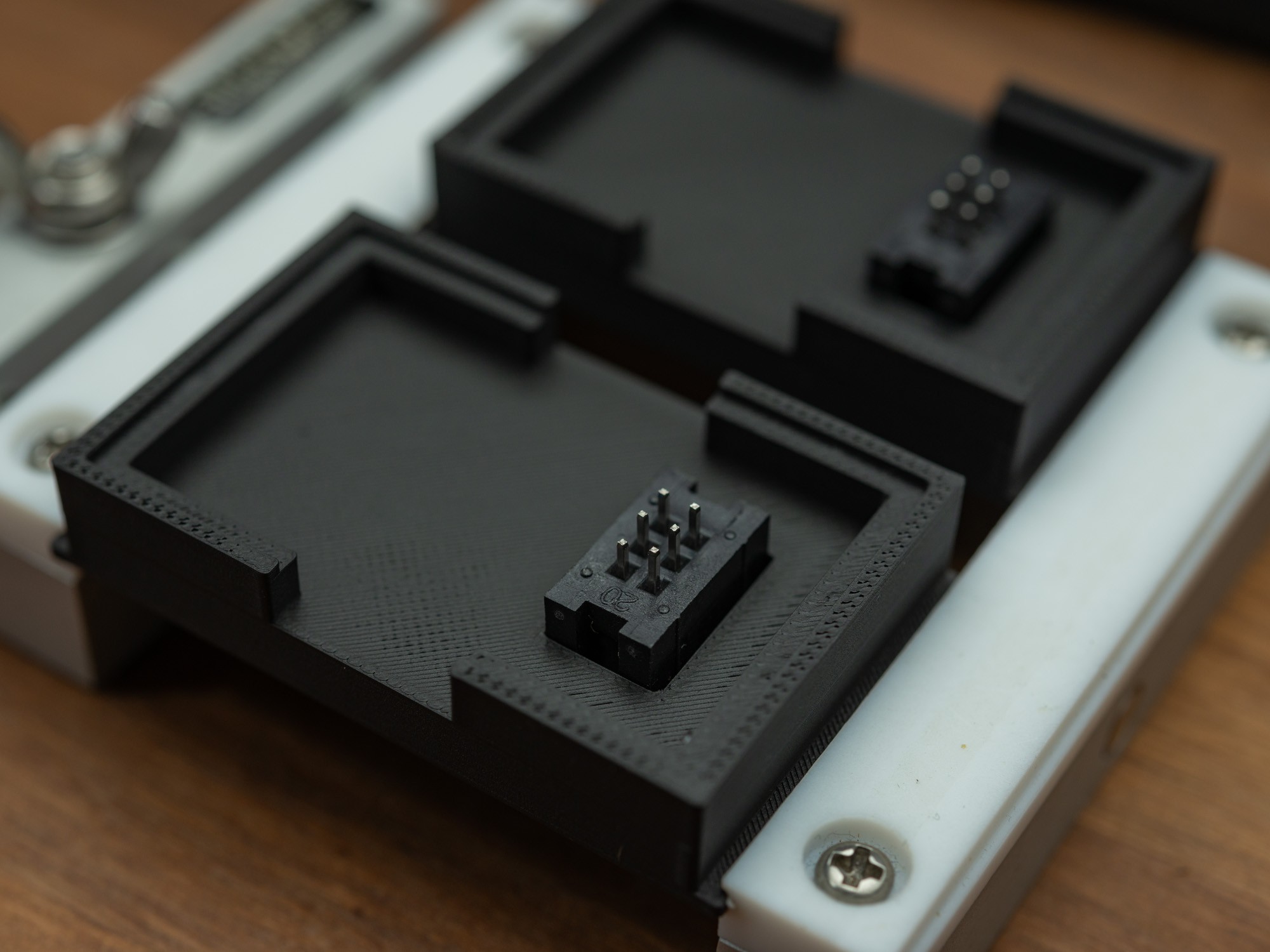
The jig also have a small notch to make sure the connector is oriented correctly, which did save me a couple of times.
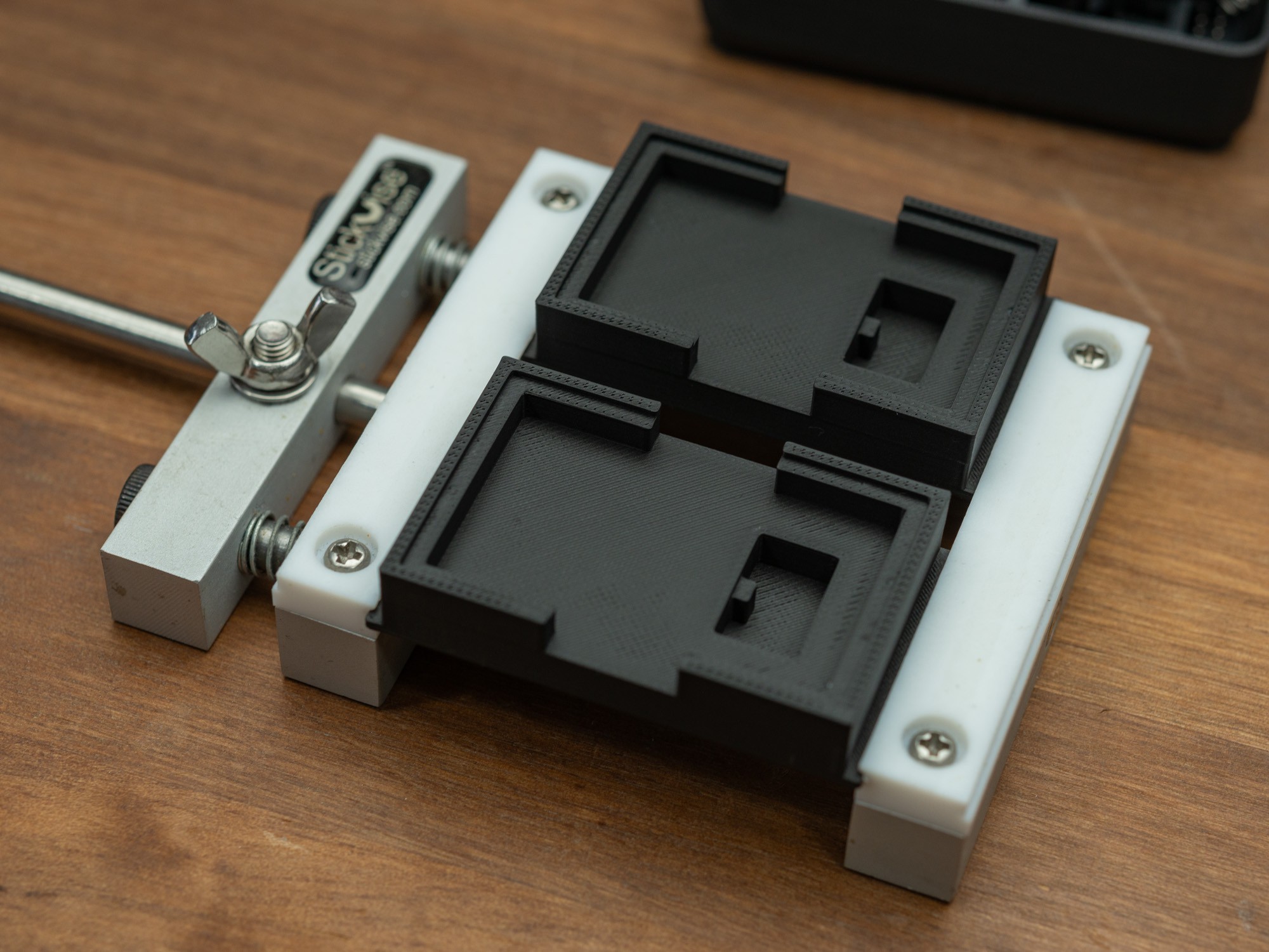
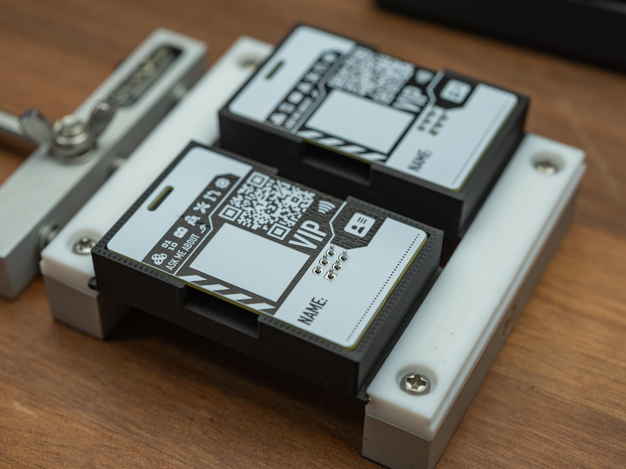
The PCBs then sin on top, and the weight of the Stick Vise, helps it to stay put, when using both hands to do the soldering. I made to jigs in an attempt to optimise context switching, and it worked quite well.
I manage to solder all the boards before it started to get boring.
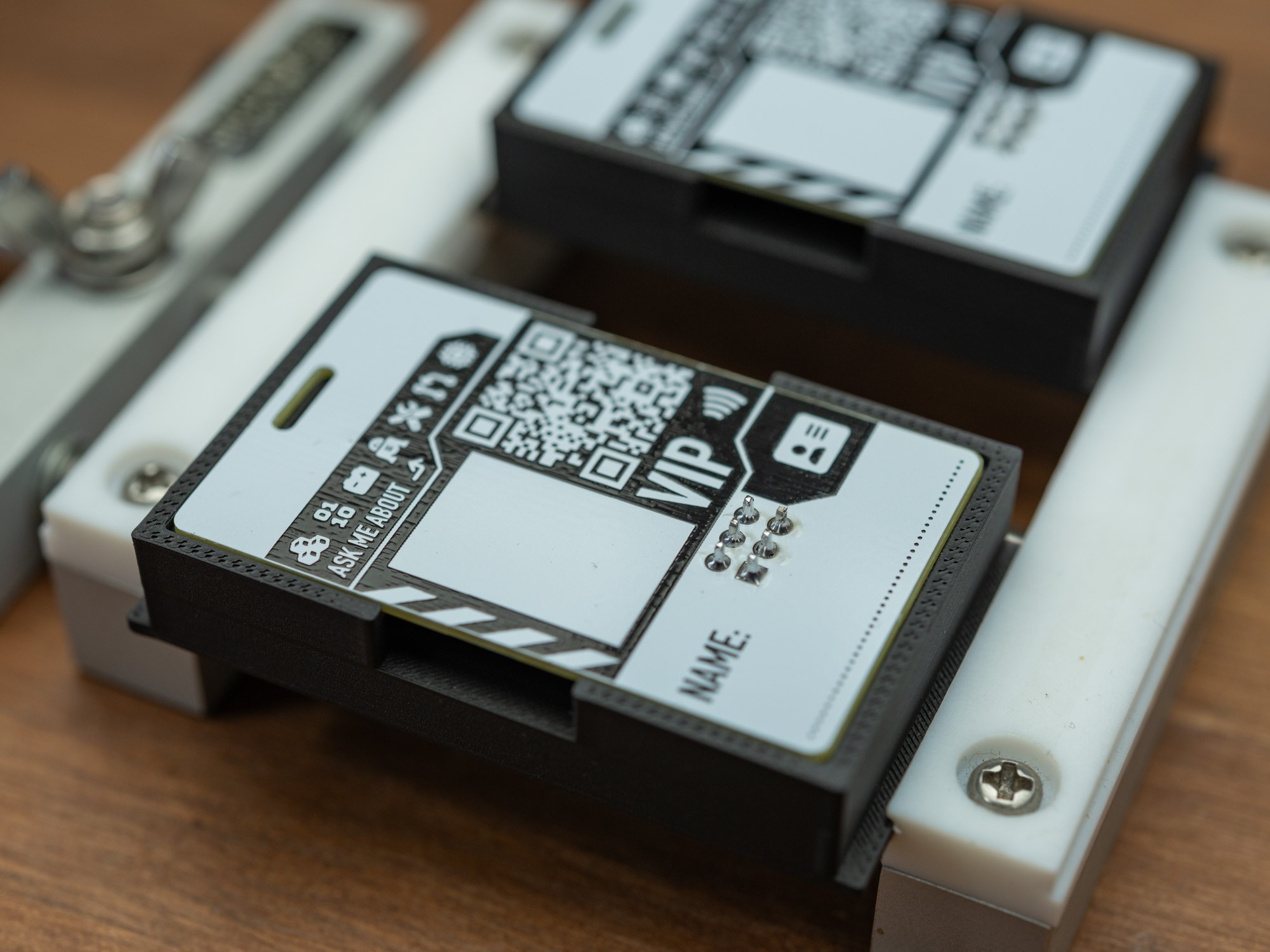
The trays only fit half as many, when the connectors are mounted, but they do stack.
Discussions
Become a Hackaday.io Member
Create an account to leave a comment. Already have an account? Log In.
I really like the assembly jig idea! I have been free-handing everything during assemble and it's tedious. Using a clothespin to hold an OLED in place squarely etc. A 3D printed jig makes a lot of sense!
Are you sure? yes | no
Yeah... if it's just one or two, probably not worth the time, but when doing a small production, it makes life easier, and less error prone.
Are you sure? yes | no