I had ordered these pipe NTCs from aliexpress for $2.42. They fit well around the outlet pipe of my boiler. They are is 10kohms at 25 degrees Celsius and has a beta of 3425 in the range 25 to 85 degrees.
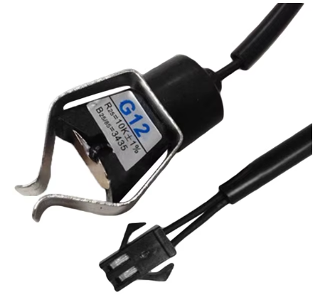
The NTC is used as the second element in a voltage divider.
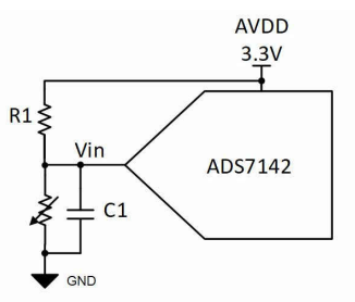
R1 is selected based on the temperature being monitored. R1=Sqrt(R1+R2). I want the voltage divider to be most linear between 25 and 100 degrees Celsius. The NTC resiatnce values can be looked up from from an online calculator

so R1=Sqrt(10k+1k)=3.3kohm.
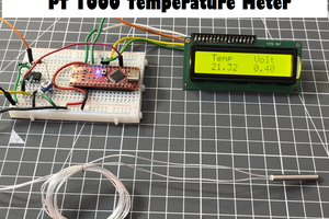
Then I selected this Wemos C3 mini board to perform the ADC measurement and to send the measurement data to the internet.

However I found the ADC is very non linear. The ADC value never reaches 0 and it clips clips above ~2.5V

So I decided to use an external ADC such as the 16-bit ADS1115. It connects to the microcontroller through I2C and it has an internal voltage reference for the ADC so the values never depend the power supply voltage. It has on board pull ups for the I2C signals.

I sticked the ADC board it to the back of the micrcontroller board, added a 3k3 pull up resistor R1 and soldered small wires


I soldered the NTC wire to the board and clipped the NTC on the boiler water outlet pipe.

The programming was done in Arduino. I used someone elses code and modified it. First in embedded code some constant values are defined. R1 value I had measured using my multimeter
#define nominal_resistance 10000 //NTC resistance at 25⁰C
#define nominal_temperature 25   // temperature for nominal resistance
#define beta 3435  // The beta coefficient of the thermistor, check the datasheet for the accurate value.
#define R1 3288   //Value of  resistor used for the voltage divider
Then in embedded code I set the ADC converter gain. Since my values are always between 3.3V and GND I selected 1x gain, which is +/-4.096V
ads.setGain(GAIN_ONE); // 1x gain +/- 4.096V our range is 0-3.3V
Each step of the ADC converter is 8.192V/2^16=0.000125V
The NTC resistance is calculated using this formula
NTCresistance = R1/((26400.0/adcValue)-1); //26400 represents 3.3V/0.000125V
where 26400 is the ADC value at 3.3V (3.3V/0.000125V)
Following code calculates the temperature
  temperature = NTCresistance / nominal_resistance;   // (R/Ro)
  temperature = log(temperature);                     // ln(R/Ro)
  temperature /= beta;            // 1/B * ln(R/Ro)
  temperature += 1.0 / (nominal_temperature + 273.15);// + (1/To)
  temperature = 1.0 / temperature;                    // Invert
  temperature -= 273.15;                               // convert to
I have verified the temperature with boiling water and melting ice and found 100.9 and 0.4 degrees Celsius, so that is very accurate.
And finally the data is sent to thingspeak once per minute.

The small antennas is the real temperature when the water from the boiler flow through the pipe. When the flow stops the pipe cools down in ~10 minutes. The large increase in the middle is the weekly desinfection of the boiler, to prevent legionella , it heats up to 60 degrees celsius. On other days it heats up to 46 degrees Celsius. You can see temperature drop about 6.25 degrees Celsius per day. The temperature shown in the chart matches the temperature that my boiler reports, so I still could not explain how I could have a comfortable warms shower while my heat pump indicated only 32 degrees.
 Jasper Sikken

 Est
Est
 RoGeorge
 Lithium ION
Hi, great project! It's very well documented. Have you considered using a DS18B20 sensor instead? I always use them because I find the analog-input conversion a bit tedious.