 SUF
SUFx
0%
0%
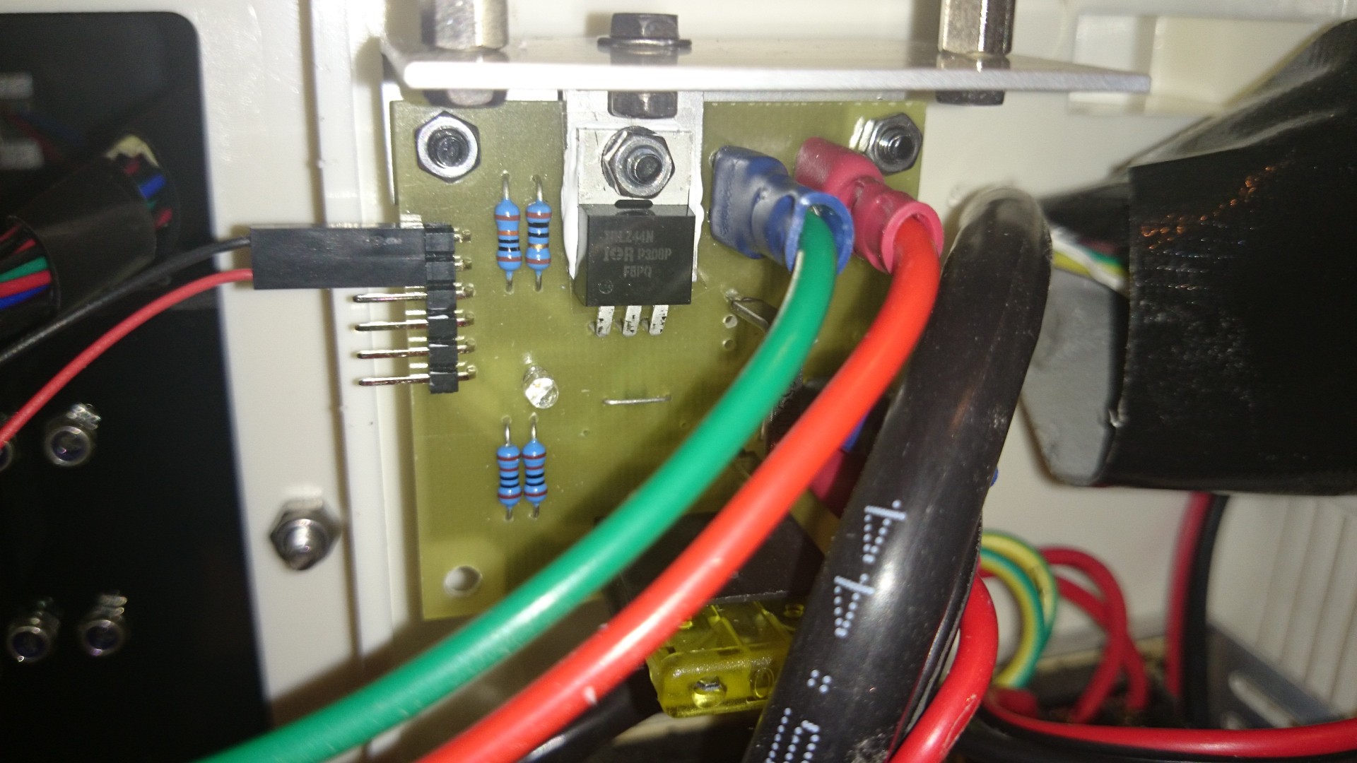
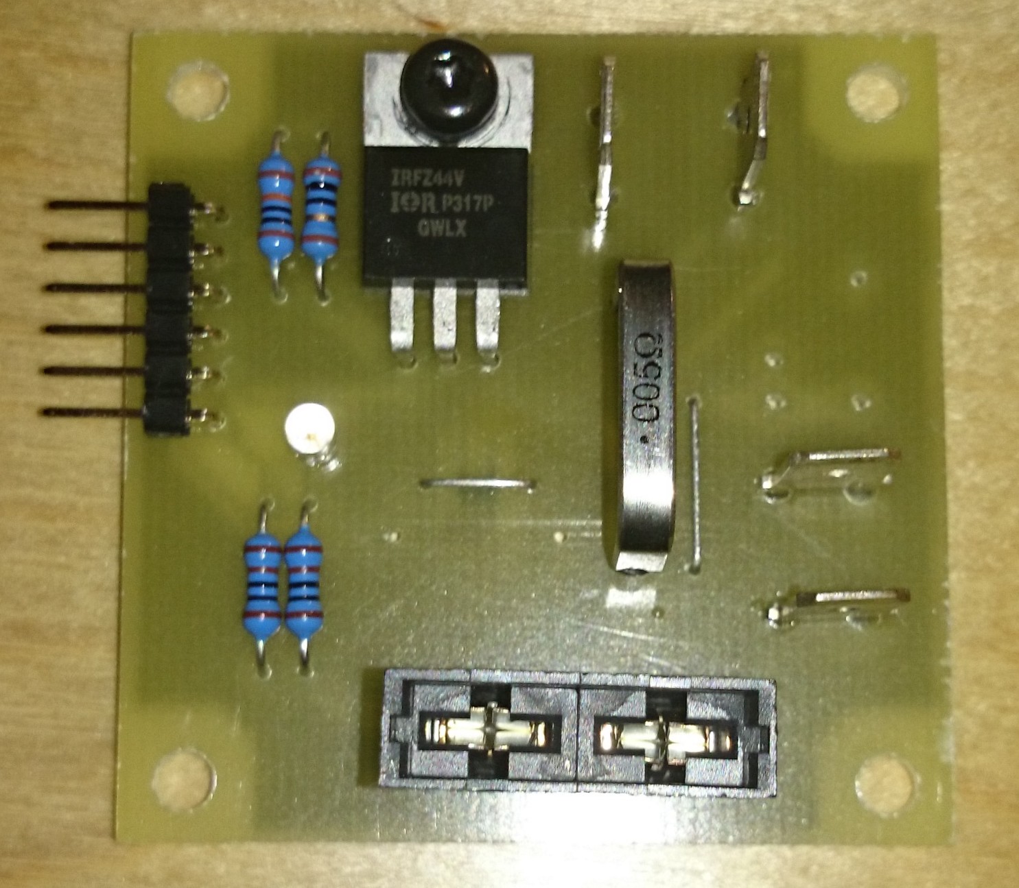
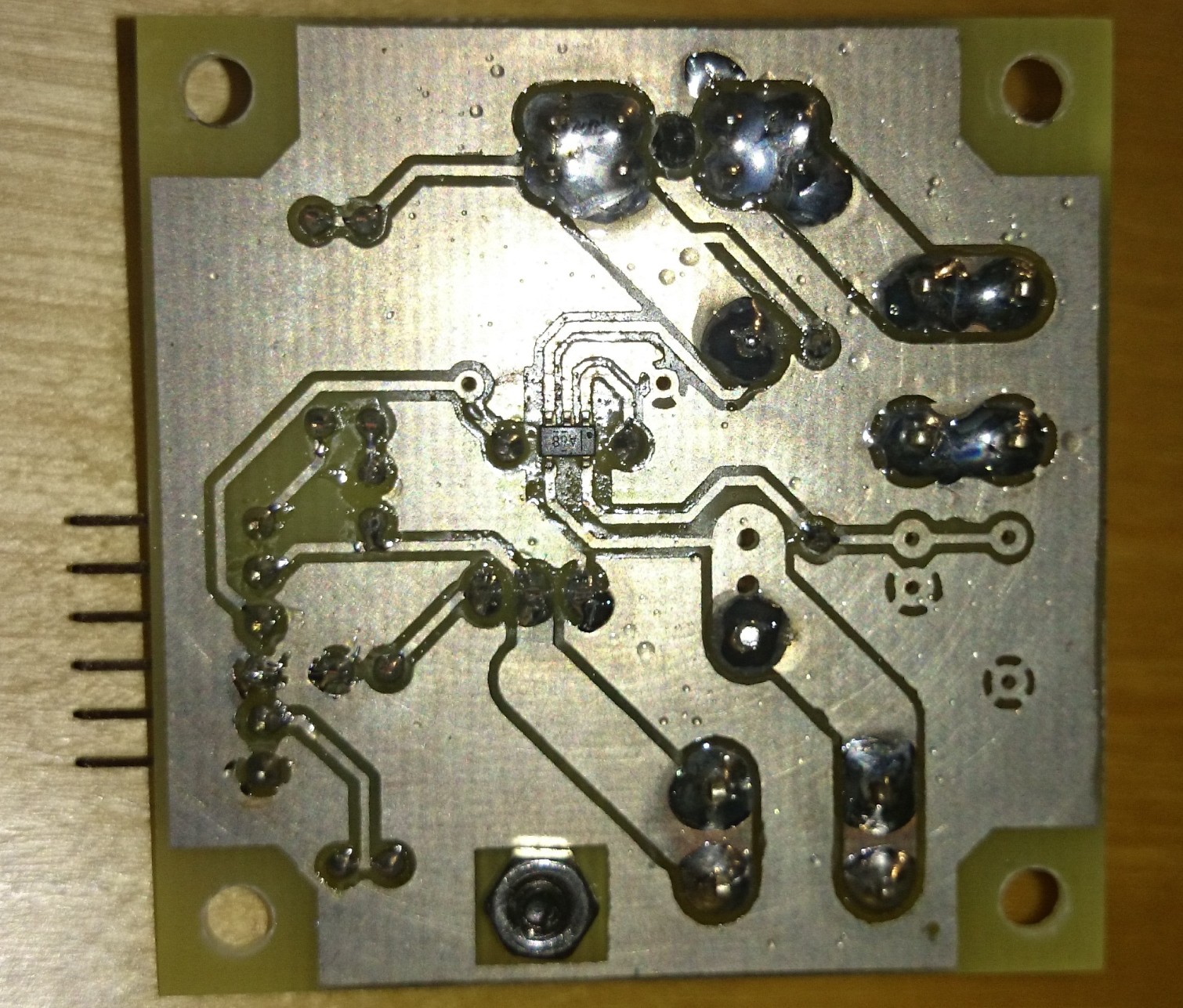
MOSFET Mania
Various MOSFET driving circuits for various projects
Become a Hackaday.io member
Already have an account? Log in.
Just one more thing
To make the experience fit your profile, pick a username and tell us what interests you.
Pick an awesome username
hackaday.io/
Your profile's URL: hackaday.io/username. Max 25 alphanumeric characters.
Pick a few interests
Projects that share your interests
People that share your interests


 Adrian.l.west
 Ramón Calvo
 Tanguy
 Mark Howe
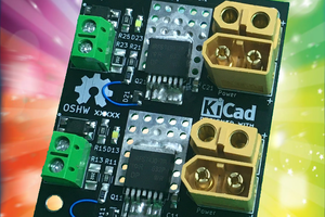
The hotswap controllers can be think of as a MOSFET controller that protect against faults. Isn't that what you are building around your MOSFET?
You can size the MOSFET for your voltage/current. The Safe Area Operation (SOA) is what is a pain to implement if you are going discrete. I hope you are familiar with MOSFET parameters know what they means far beyond just voltage and current ratings.
> I want to make it a little bit more versatile therefore I plan to add INA193-INA195 also as an option. This ones are not able to work from 48V supply so in addition I'll add a zener based regulator as an option.
That's the reason why I pointed out high voltage linear and SMPS regulators that are designed for providing a low voltage for your control circuits i.e. INA193-INA195
Or are you responding to mr.jb.swe ???