Michael O'Toole
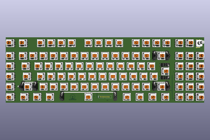
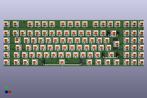
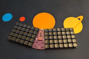
Hardware: Micro, Keys, etc...
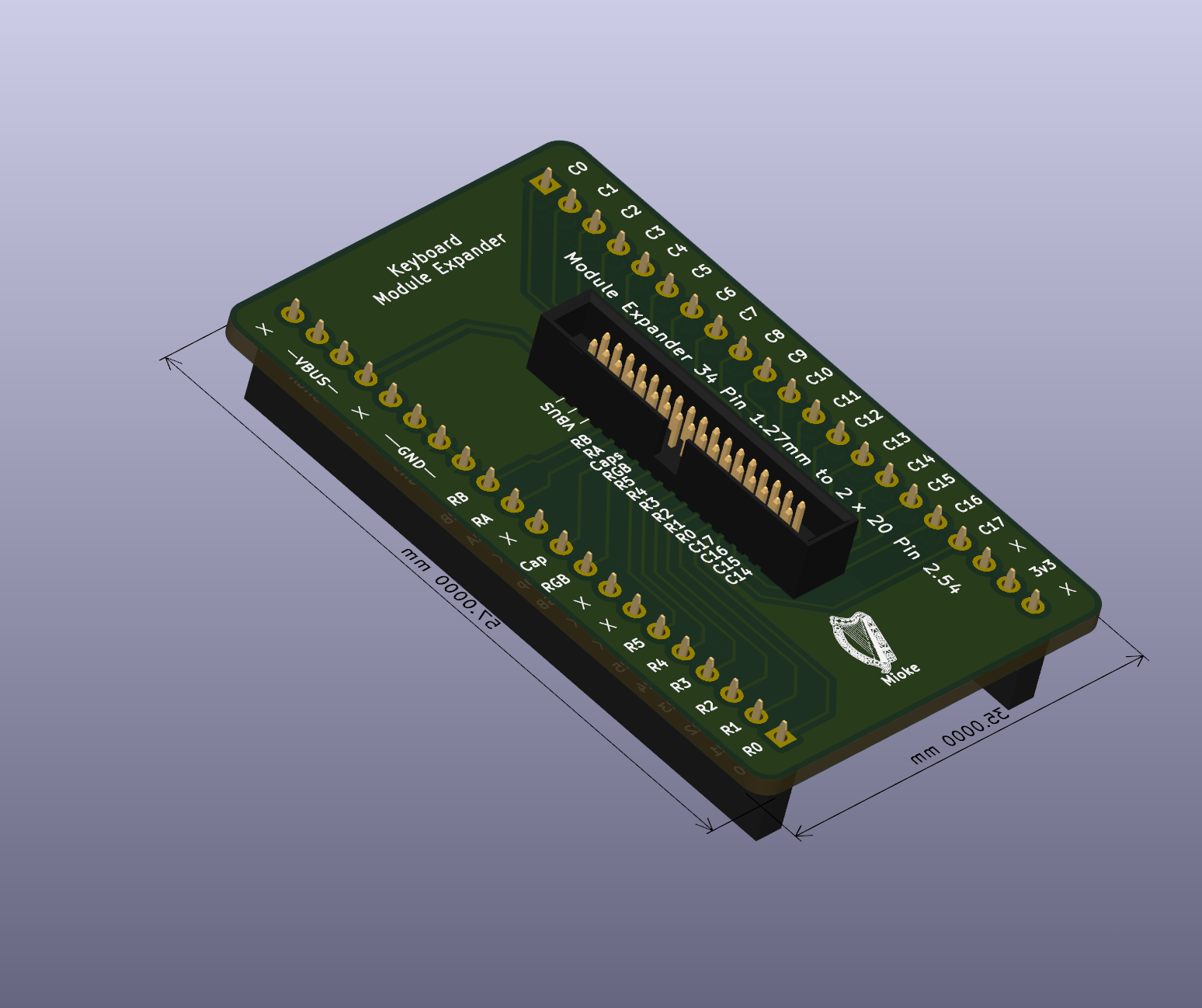
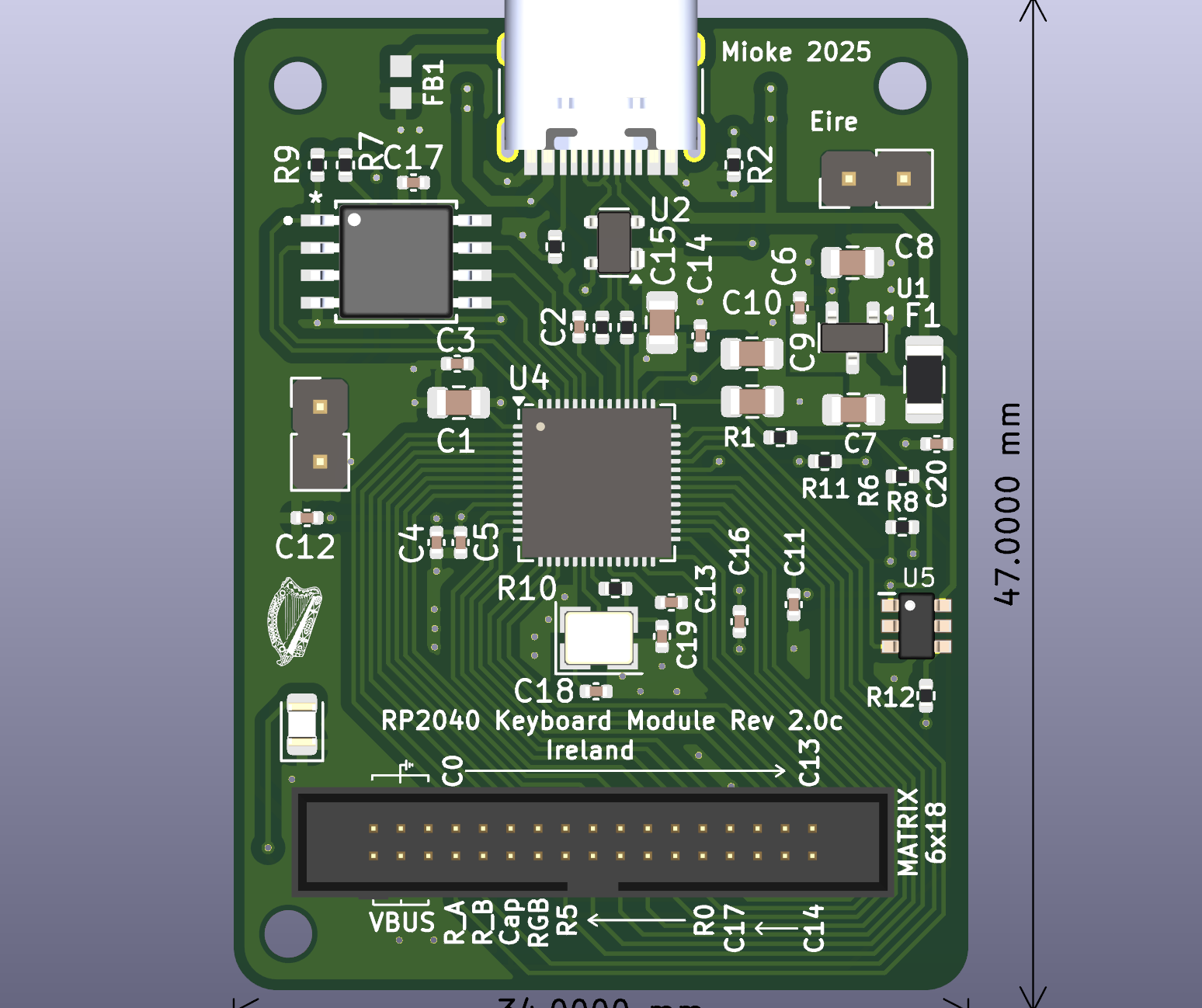
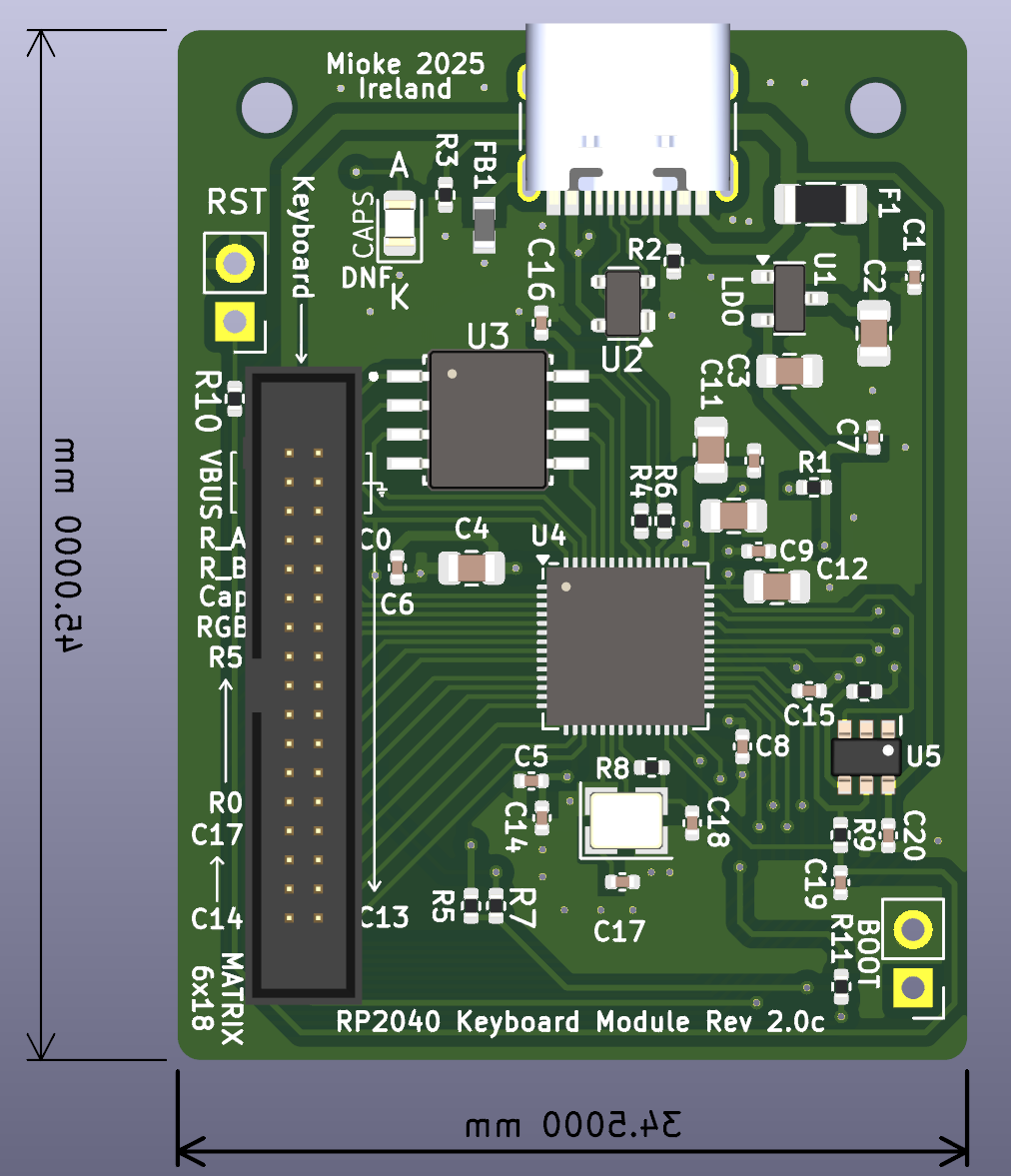
Micros: RP2040 and STM32F411RETx (default is RP2040)
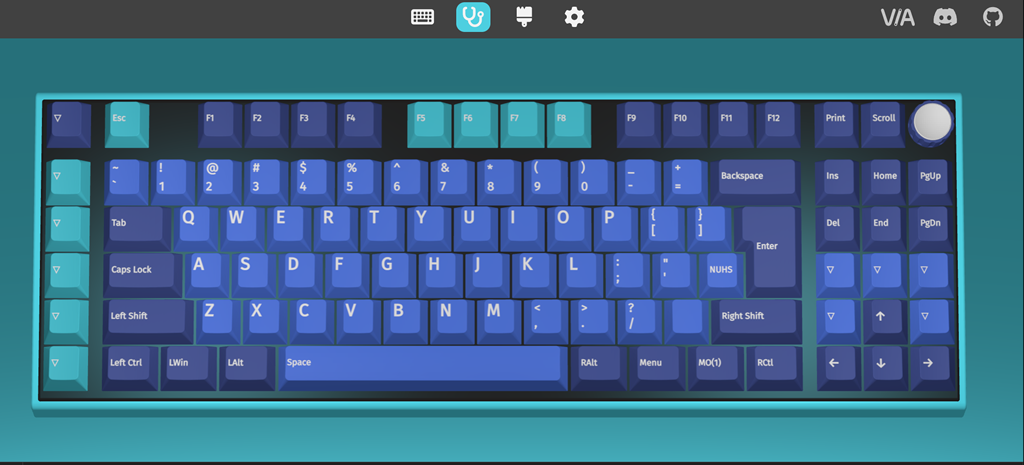
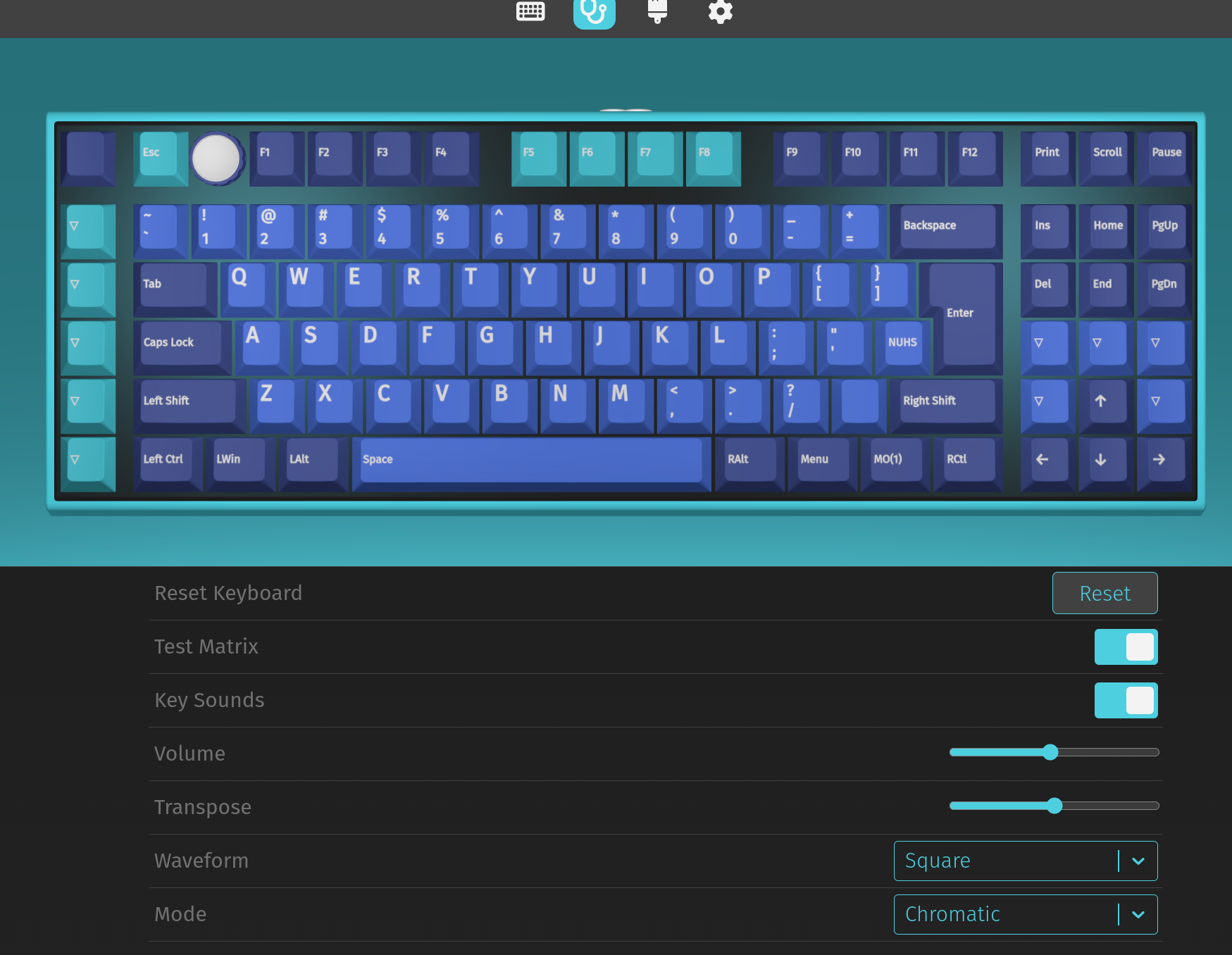
Software Support: QMK/VIA
Switches: MX type hot-swappable
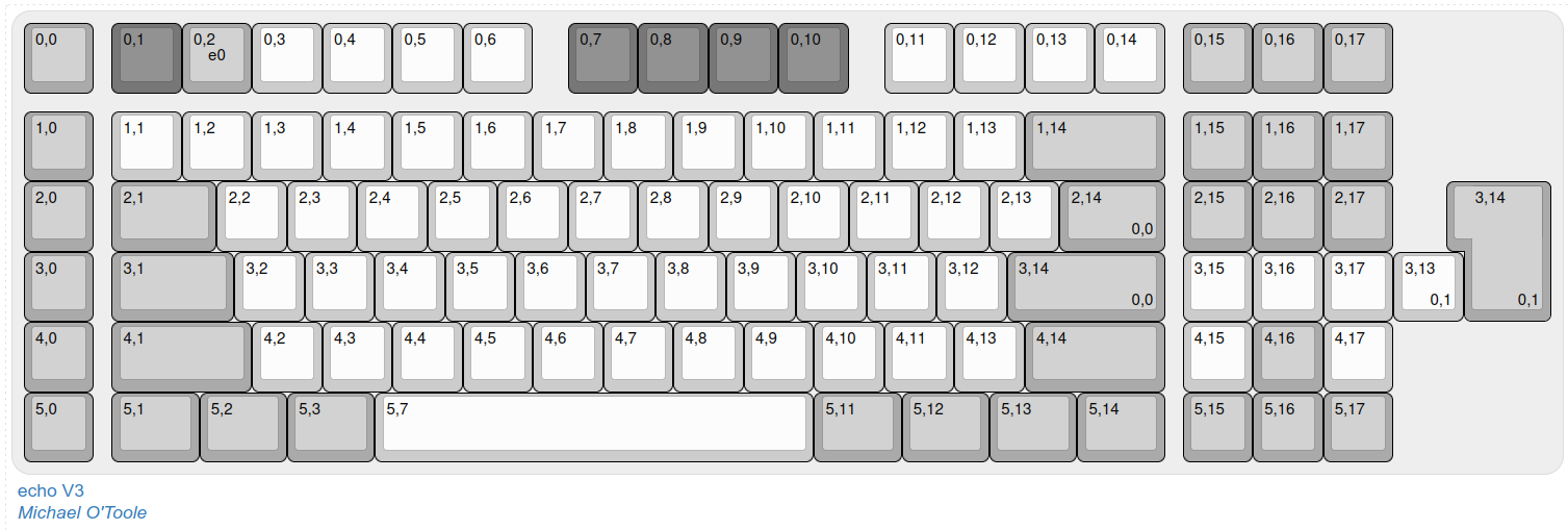
Keys: Up to 119 Keys (including Macro Keys) + Encoder Switch
Rotary Encoder: Volume / RGB.
Tools:
- Kicad version 9, release build...
- Plugins: KLE Placer (saves so much time with layout, a must have).
- QMK Configurator
Other references:
keyboard-layout-editor.com
See GitHub Kicad files and Code...
Added a 3d printed case (in two parts), tweaking before uploading. It has a section to hold the module board secure and should be the most economical solution. Files for a FR4 plate are also available, they cost about €5 from PCB Way...


 deʃhipu
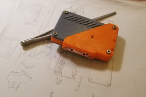
 Christian