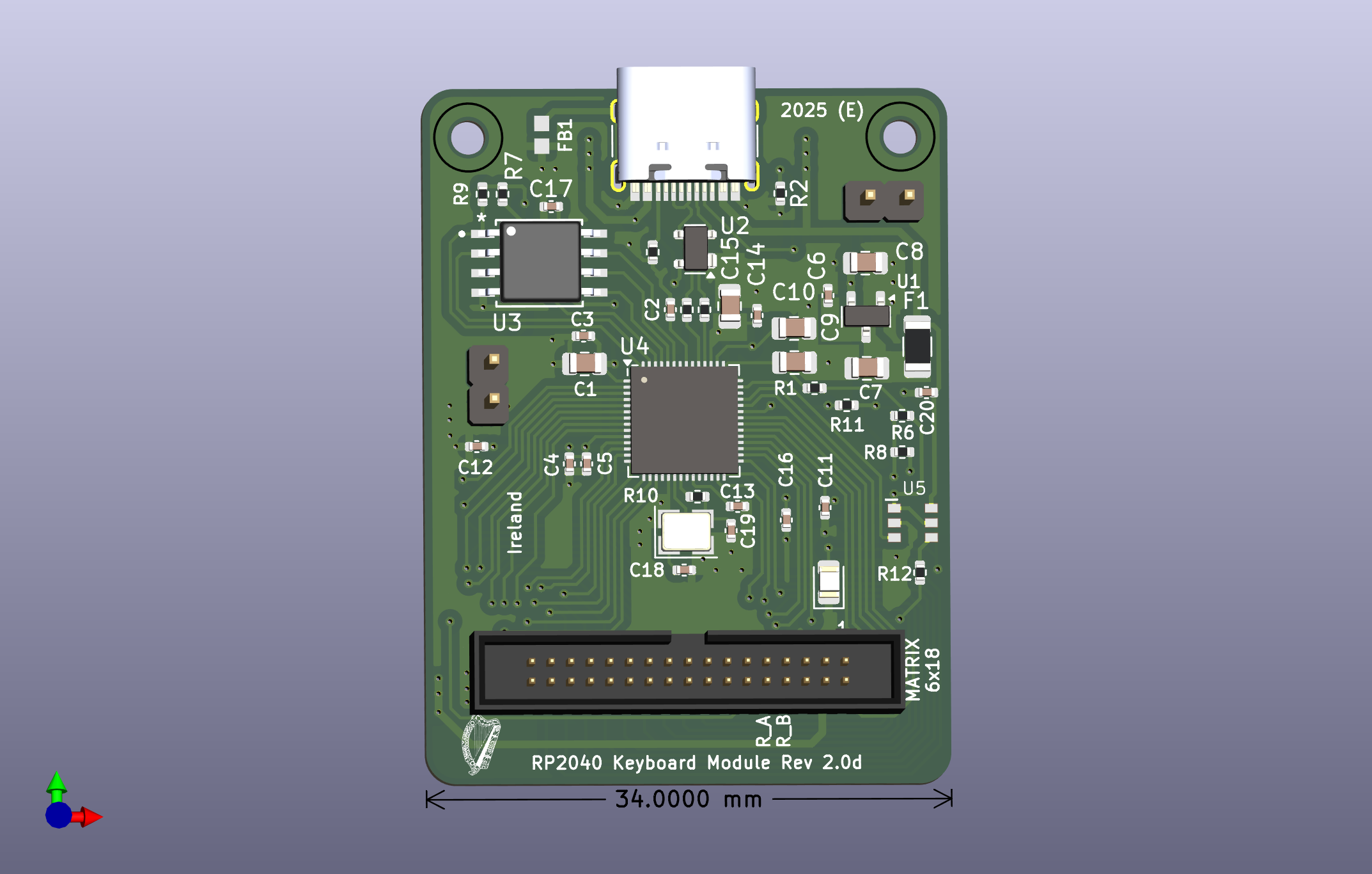
In version C, the IDC connector had to be mounted to bottom of PCB (I screwed up the orientation)...It work perfectly but I would prefer all components on the same side (aesthetic/logical), so to Version D.
Version 2.0D has been tested and works perfectly, once again, thanks to PCBWay for the fabrication.
As to a keyboard, you can use my Basic Keyboard design (hand assembled, just need PCB and parts), or you can design your own, be it a keypad, macro pad or full sized keyboard...
The important point is you don't have to design the logic, just use the Keyboard Module and you are QMK/VIA ready. Just change my code to suit your needs...
If your wondering how you can test your code, I include a breakout / breadboard friendly converter PCB here... (includes link to Gerber Files and KiCad Files)
Just completed tests with latest (and last) basic Keyboard (EN014) using my Keyboard Development Module version 2.0 and everything worked perfectly including the RGB.
The EN014 Keyboard differs only in the position of rotary encoder was moved to left of the Print key allowing for better spacing of function keys and, moving of the Caps Lock Led to top side of PCB (beside the caps lock key).
The EN014 board was tested with version 2.0D of the keyboard development module (34 pin connector), basically both boards and the code were validates, as was the new keyboard plate...
Testing the Module with the 34 pins 1.27mm connector is almost impossible so I added an adapter board.
This board is breadboard friendly if you use pin headers, with pin sockets you can use common 2.54mm jumpers. Note, this adapter is for modules with the 34 pin connector version 2.0d (14/01/26)
New Breakout / Breadboard Friendly board for testing the latest module (V2.0D)
The development board is fine for testing code and now you can check button action with the extender. Once your happy, you can plug it into one of the basic keyboard with the 34 pin socket in the project and you have a QMK/VIA keyboard with macros and RGB...
To date I have designed three version of the Keyboard Development Module, each having slight changes...
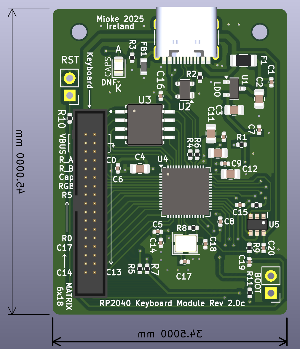
The first provided four test RGB leds and used a 30 pin connector and a three pin connector for the RGB, the second removed the RGB leds, simplified the Boot, Reset switches and changed to a single 34 pin 1.27mm connector.
The third and last version, is identical to the second but changes the position of the connector making connection to the basic keyboard easier and more natural.
All three modules work perfectly for developing and testing QMK/VIA code but once you are finished your code development, I want to be able to use them on the actual keyboard. To this end I provide several basis keyboards containing all the necessary parts allowing connection to one of the modules.
All versions of the modules were tested and worked fine, but you have any interest in the module, I'd go with Version 2.0D. I have also included a design for a small converter board, it allows the module to connect to a breadboard... See: My Git and Adapter Board
The final version pictured below.
This is powering my current keyboard (along with the basic keyboard EN014)
It appears to be more cost effective to use a module as opposed to building a keyboard including the full electronics from the beginning. As you can hand assemble the keyboard as all components are pretty easy to hand solder and getting the modules fully assembled is cost effective, less than €20 and a keyboard PCB was about €10 each.
The FR4 Plate cost about €5 but prices have since increased, appears I got a real bargain at the time (no tooling charges).
The original module with the built in RGB test Leds is perfect for developing code but the two different connectors aren't really necessary if after the development you then use it to control/make an actual keyboard.
I have upgraded the module to use a single 34 pin connector and replaced the two switches with pin headers. The extra pins also allow adequate current for the RGB Leds, considering your PC's USB supplies 2 Amps Max @ 5V.
In tests at full brightness, the keyboard draws just under 1.2 Amps from the USB. Each pin on the connector is rated at about 1 Amp (we now use 3 pins for supply and ground).
There are two major advantage to using a Module and Basic (bare-bones) Keyboard as apposed to getting a fully assembled keyboard...
Reduced Costs as Keyboard can be assembled by hand (parts are easy enough to solder)...
The fully assembled Module is relatively inexpensive, hand assembly would be very difficult...
As the new Basic Keyboard PCB arrived I set about testing it with the Keyboard Development Module (RP2040version), and I can report a complete success, both worked perfectly...
Tested current Software ✓
The new "Basic Keyboard PCB" ✓ (change code to reverse volume up/down)...
RP2040 Development Module ✓
Keyboard Functionality ✓
Macros ✓
RGB ✓ (need to edit code to change RGB position)...
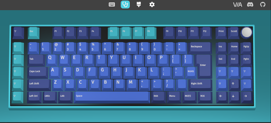
I tested the basic keyboard functionality with various programs and VIA support on the usevia web site...
Assembled boards arrived today (from PCBWay). A quick test reveals I didn't screw up as they worked perfectly, including the RGB.
The 2040 having more available GPIO's simplifies the design process and with the driver:vendor option RGB is a breeze and the flashing is easy with drag and drop, definitely the way to go for your first keyboard project.
One thing for certain, without a microscope or camera with zoom, hand soldering these tiny devices would be a major challenge for anyone and not recommended for your average hobbyist or old engineers like me.
The cost of 5 boards (3 completely assembled and 2 empty), including courier amounted to $87.34. That's about $22 per assembled board which is as good as it gets... I should have got all the boards assembled, I will in future.
Next Step:
It would be tempting to just add the electronics from the dev board to the main keyboard PCB and call it a day, but as I now have 3 perfectly good RP2040 Keyboard Modules, I think I go with a basic keyboard PCB, that is a board with only the switches, diodes, RGB leds and the 30 pin connector. This also has the advantage of being able to repurpose it for use with other modules.
There is no difficulty in hand assembling the bare-bones board as the diodes, hot-swappable connectors and RGB are easy enough to hand solder, thereby reducing the overall cost.
 Michael O'Toole
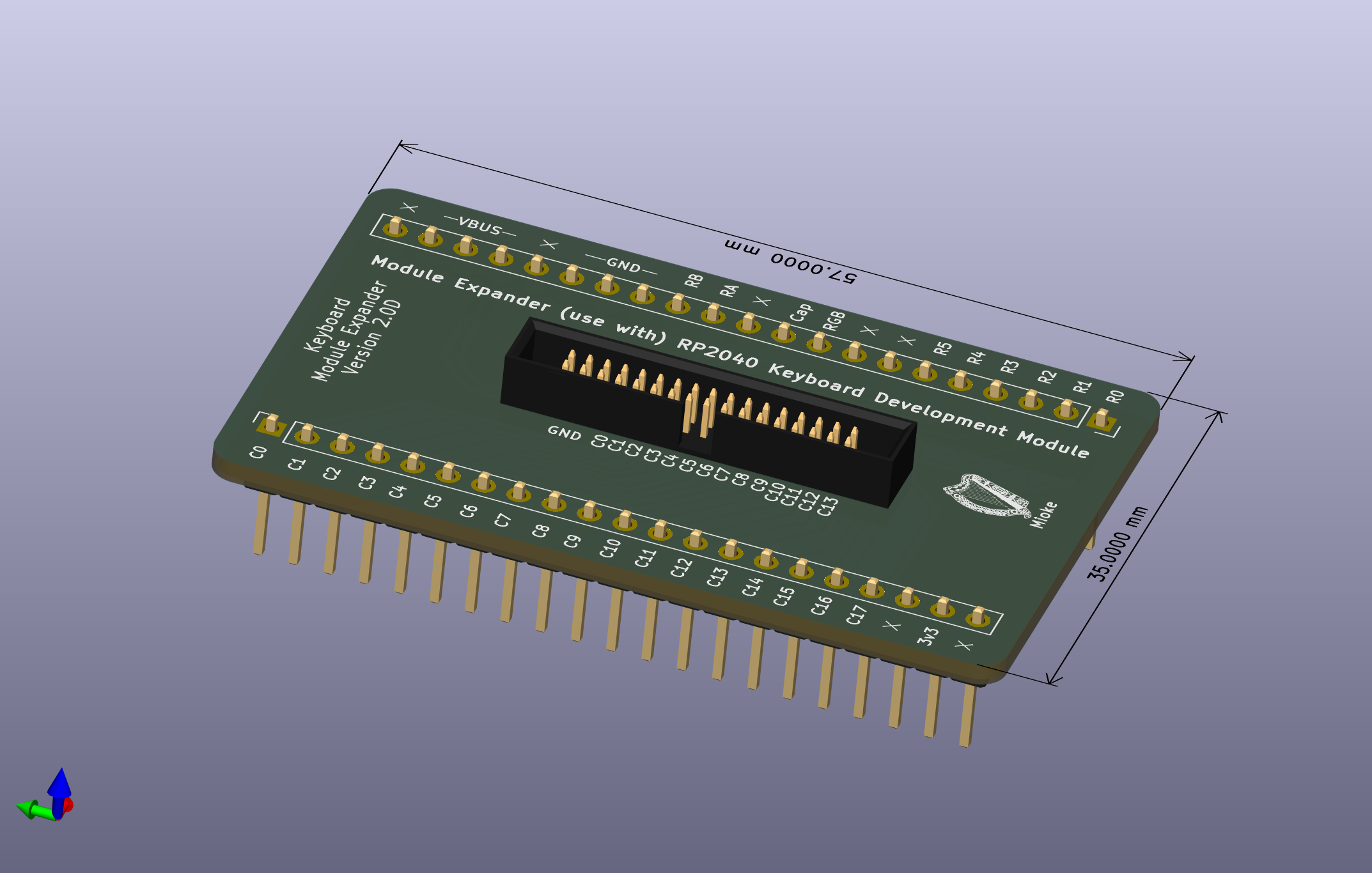
 This is powering my current keyboard (along with the basic keyboard EN014)