 Michael O'Toole
Last Updated: 14th Jan 2026
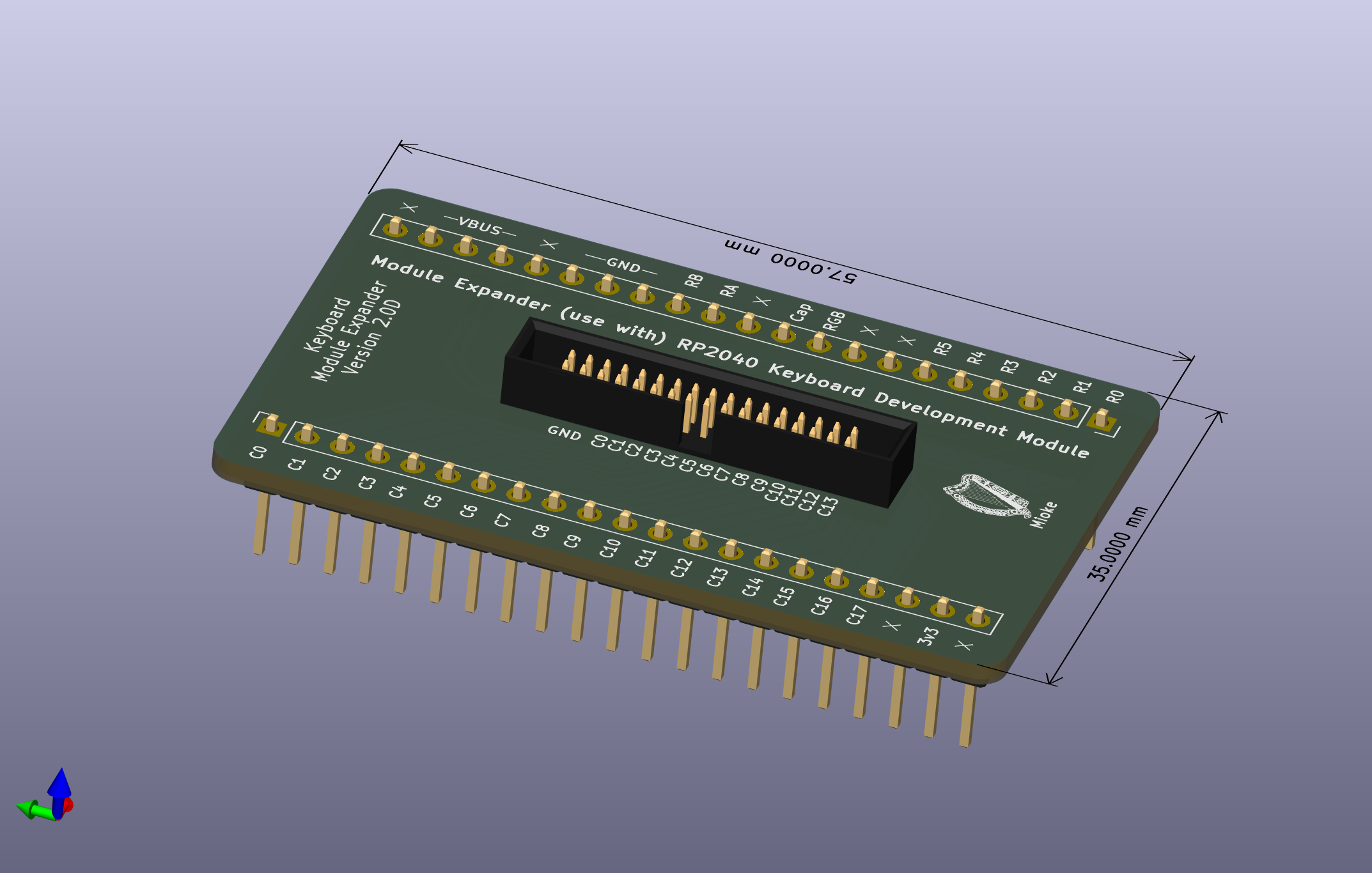
Module: Module34D Keyboard: EN014
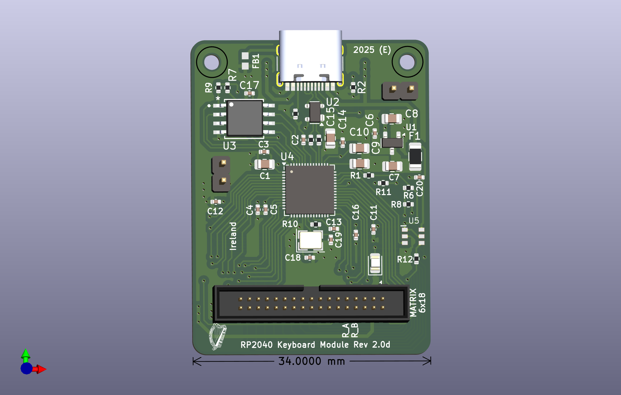
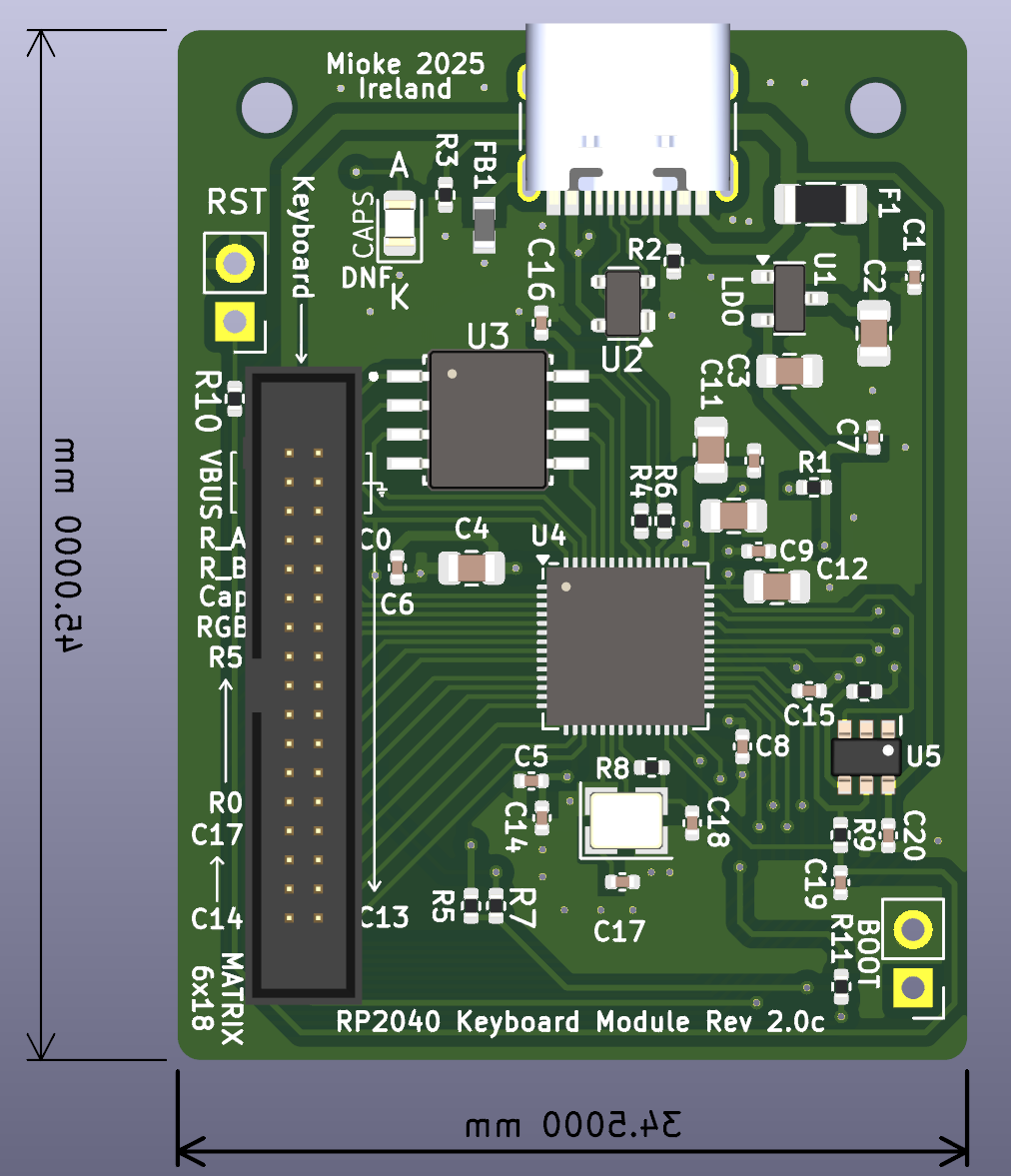
Micro: RP2040 (note, STM32F411RETx code for RGB is not complete, use RP2040)
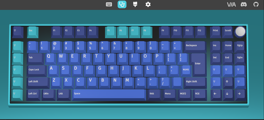
Software Support: QMK/VIA
Switches: MX type hot-swappable
Keys: Up to 119 Keys (including Macro Keys) + Encoder Switch
Rotary Encoder: Volume / RGB.
Code: see my Git Repo.
Prototype PCB's: by PCBWay
Current Version: 2.0 D (please use latest version only).
Essential Tools:
- Kicad version 9, release build...
- Plugins: Keyboard Layout Editor Placer (saves so much time with layout, a must have).
- QMK Configurator
- usevia.app (Chrome) Web tool to test & edit your keyboard (keys/macros etc.), a must have...
- Keyboat-Layout-Editor.com (Web tool to design/edit/save your Keyboard Layout)...
Other references:
See GitHub Kicad files and Code...
Added a 3d printed case (in two parts), tweaking before uploading. It has a section to hold the module board secure and should be the most economical solution. Files for a FR4 plate are also available, they should cost about €5 but you can also print the plate as I did for the first prototype.
Please check the plate file in Kicad as I may have mixed these up, make sure the switch cut out and rotary encoder are for the appropriate PCB.
PCBWay produced five fully assembled (minus the 34 pin connector) PCB's, each costing under $20 (price includes the missing connector but you have to solder it yourself). At 1.27mm pitch, soldering requires a steady hand ;)
I should have a few to give away to anyone interested in building their own keyboard, keypad or macro key project and if there is interest, I might build a few more, otherwise you are free to use this material and build your own as this project is fully opensource...
Mike
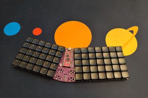
 This is powering my current keyboard (along with the basic keyboard EN014)

 deʃhipu
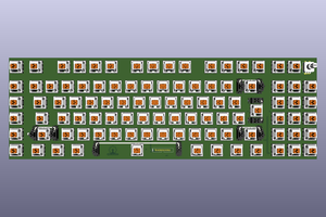
 Christian Lo
 Mx. Jack Nelson