We start by adding the 1K 1206 Resistor in its place by using a soldering iron. Here, we first add solder to one pad, then use a tweezer to pick up the resistor and melt the solder that was applied to the first pad. The resistor was then firmly fixed in place by applying solder to the other pad.
By following this method, we added all 12 resistors in their place.
Next, we placed all of the push buttons in their proper locations, including both horizontal and vertical buttons.
We secured them in place by attaching solder wire to their pads, from the back of the board.
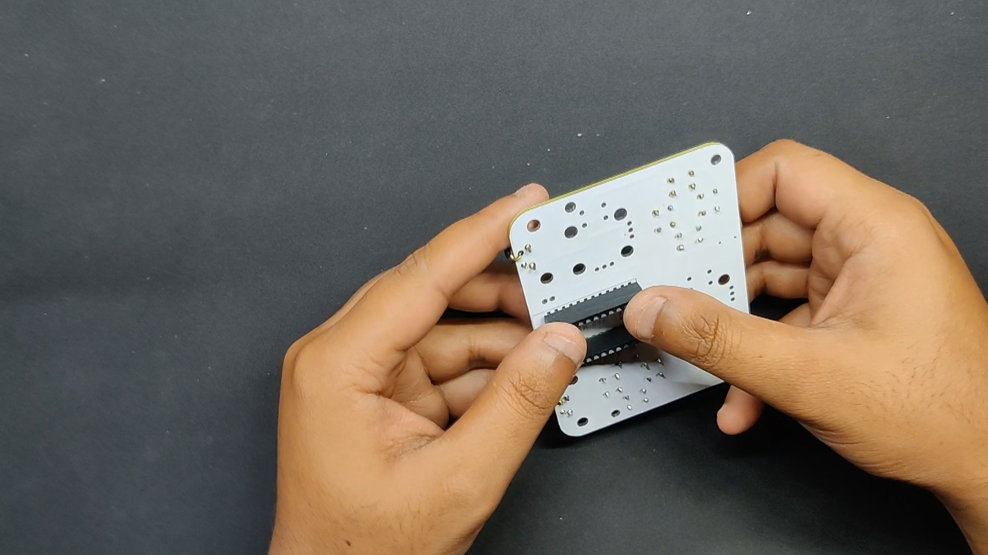
Next, we attach two CON12 header pins from the back of the board to the Arduino Micro footprint.
We solder the CON12 pads from the top side and fasten them firmly.
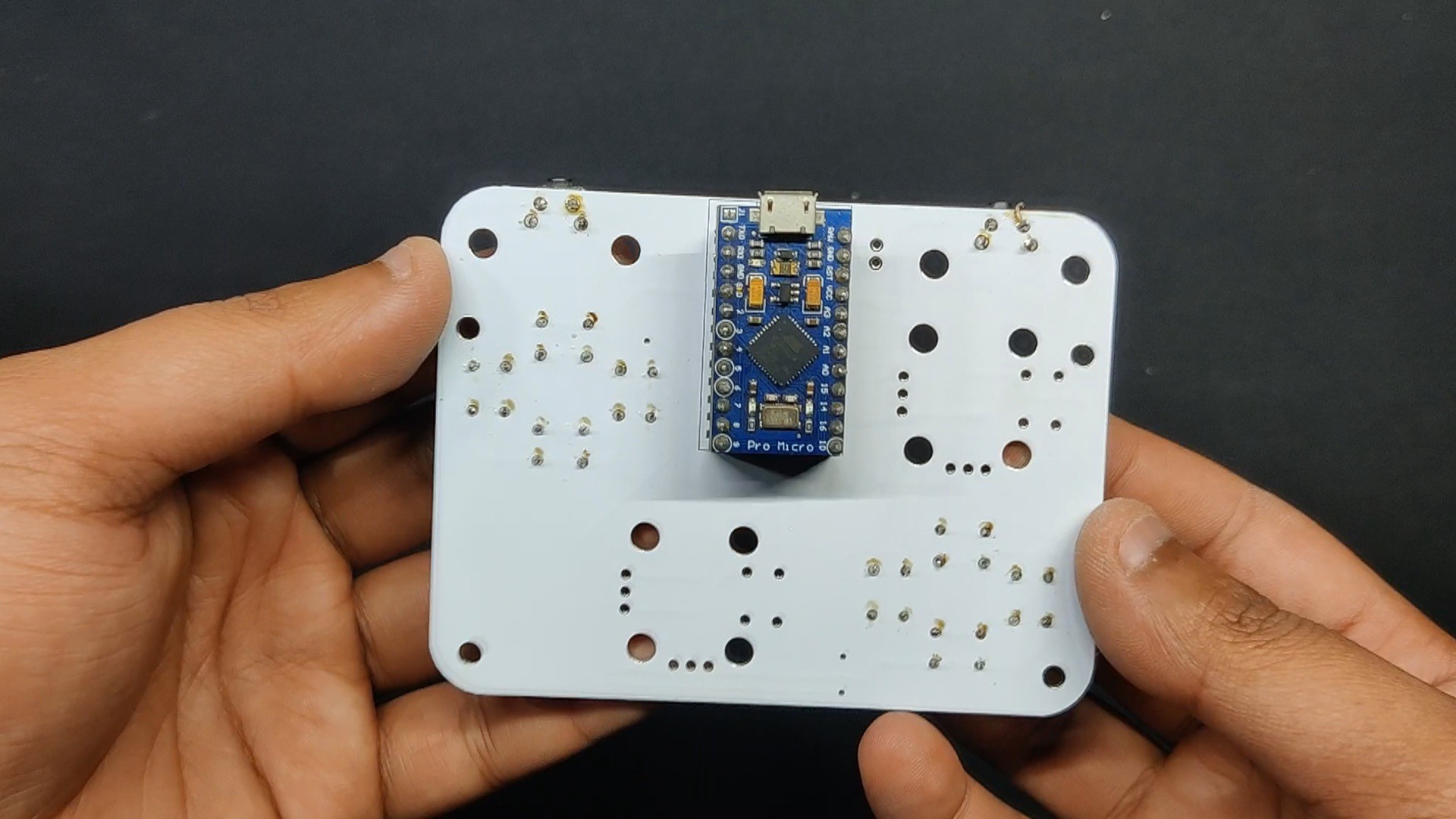
Next, we use the previously inserted CON12 header pins to connect the Arduino Micro in its location.
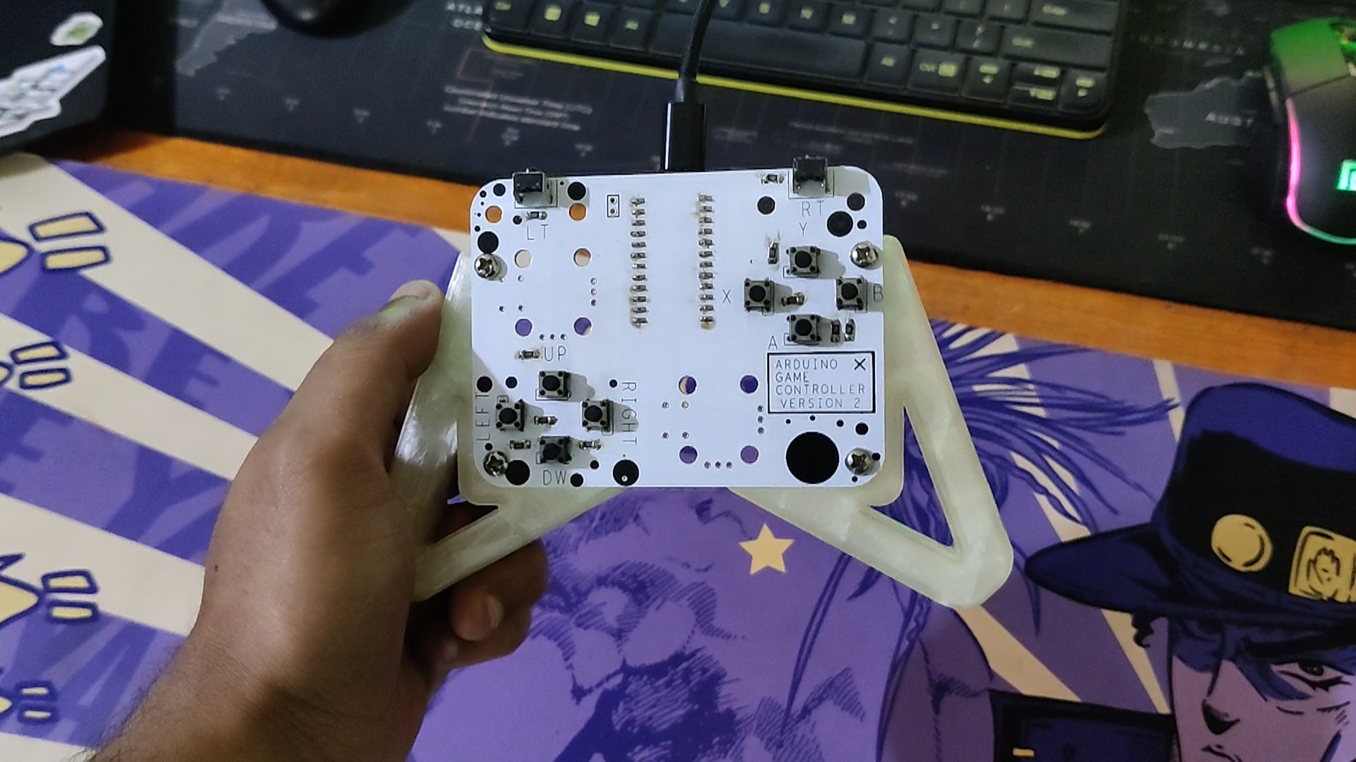
The circuit assembly is now finished.
2
Final Assembly Process
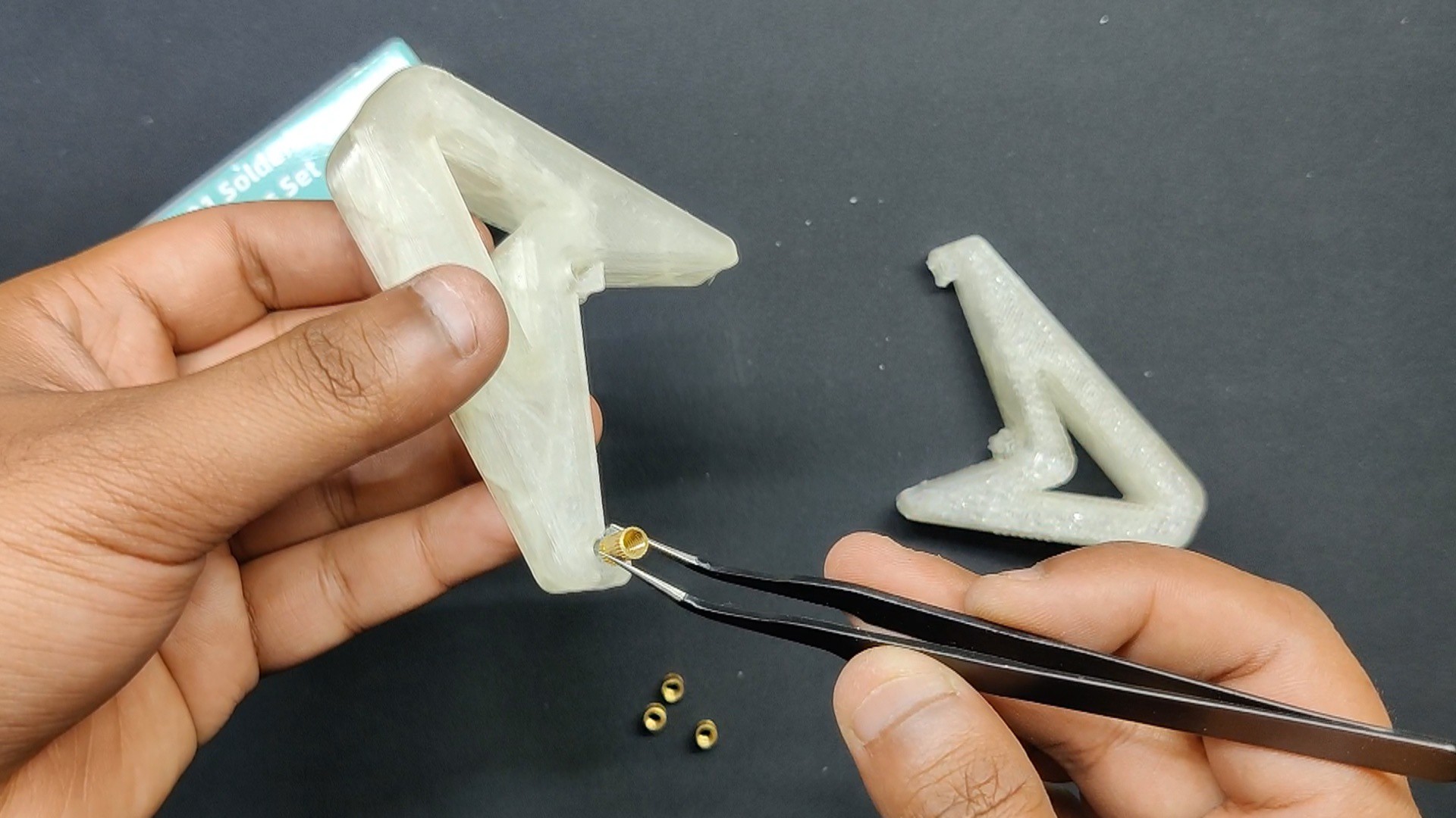
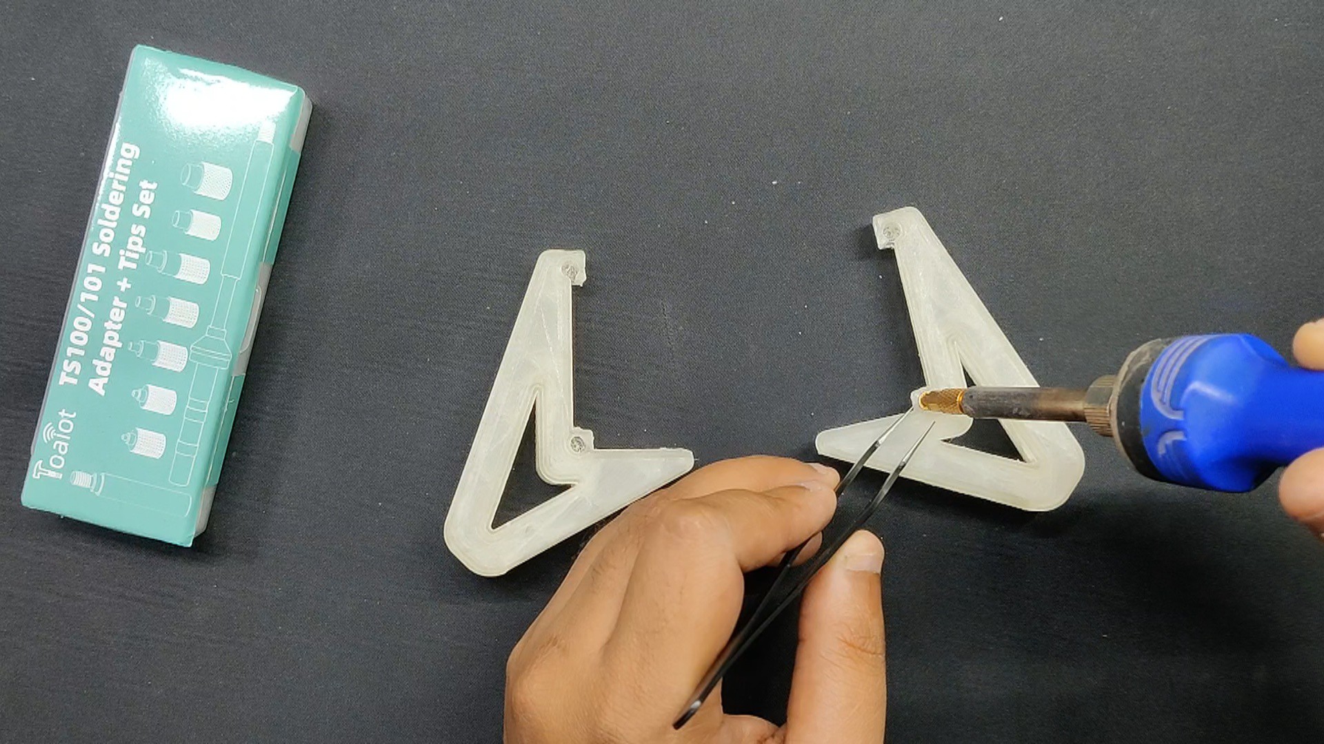
We begin the final assembly step by inserting the threaded inserts into the 3D handle's mounting holes.
Next, we use our soldering tip to heat the insert,, which forces it into place. For each of the four mounting holes, we followed this procedure.
Next, we use four M3 bolts to attach the left and right 3D-printed handles to the circuit.
Assembly is now completed.
3
CODE
We created a basic sketch for the project's code that is based on the Gamepad library, which you must install before using.
In this sketch, the single button, A0, is used to read the various values when any button is pressed. For instance, pressing the UP button yields a value of 0; pressing the Down button yields a value of 511.
Values for each button are different.
For each button, if the analog value from A0 falls within the specified range, the corresponding button is marked as pressed (true); otherwise, it's released (false).
In the below code sections, the microcontroller checks the value of A0 and sets the gamepad buttons accordingly.
if (value > -5 && value < 5) // UP gp.setButtonState(0, true);else gp.setButtonState(0, false);
The code reads an analog input from pin A0 and uses predefined ranges of values to simulate the press and release of gamepad buttons. Each range corresponds to a different button (UP, DOWN, LEFT, RIGHT, triggers, and face buttons like A, B, X, Y). The Gamepad object (gp) handles the state of these buttons by using the setButtonState() function.
To get values of each button, we used the Analog Serial Read Sketch from the example menu and used it to get values of each button.
Next, a table is prepared for recording all of the values, and tolerance values of +5 and -5 are added to the actual value. The tolerance value will be entered into the main code.
#include <Gamepad.h>
Gamepad gp;
voidsetup() {
pinMode(A0, INPUT);
}
voidloop() {
intvalue = analogRead(A0);
if (value > -5 && value < 5) //UP
gp.setButtonState(0, true);
else
gp.setButtonState(0, false);
if (value > 505 && value < 516) //DOWN
gp.setButtonState(1, true);
else
gp.setButtonState(1, false);
if (value > 762 && value < 772) //LEFT
gp.setButtonState(2, true);
else
gp.setButtonState(2, false);
if (value > 676 && value < 686) //RIGHT
gp.setButtonState(3, true);
else
gp.setButtonState(3, false);
if (value > 907 && value < 917) //LT
gp.setButtonState(4, true);
else
gp.setButtonState(4, false);
if (value > 930 && value < 980) //RT
gp.setButtonState(5, true);
else
gp.setButtonState(5, false);
if (value > 814 && value < 824) //Y
gp.setButtonState(6, true);
else
gp.setButtonState(6, false);
if (value > 872 && value < 882) //X
gp.setButtonState(7, true);
else
gp.setButtonState(7, false);
if (value > 847 && value < 857) //A
gp.setButtonState(8, true);
else
gp.setButtonState(8, false);
if (value > 890 && value < 900) //B
gp.setButtonState(9, true);
else
gp.setButtonState(9, false);
}
4
Result
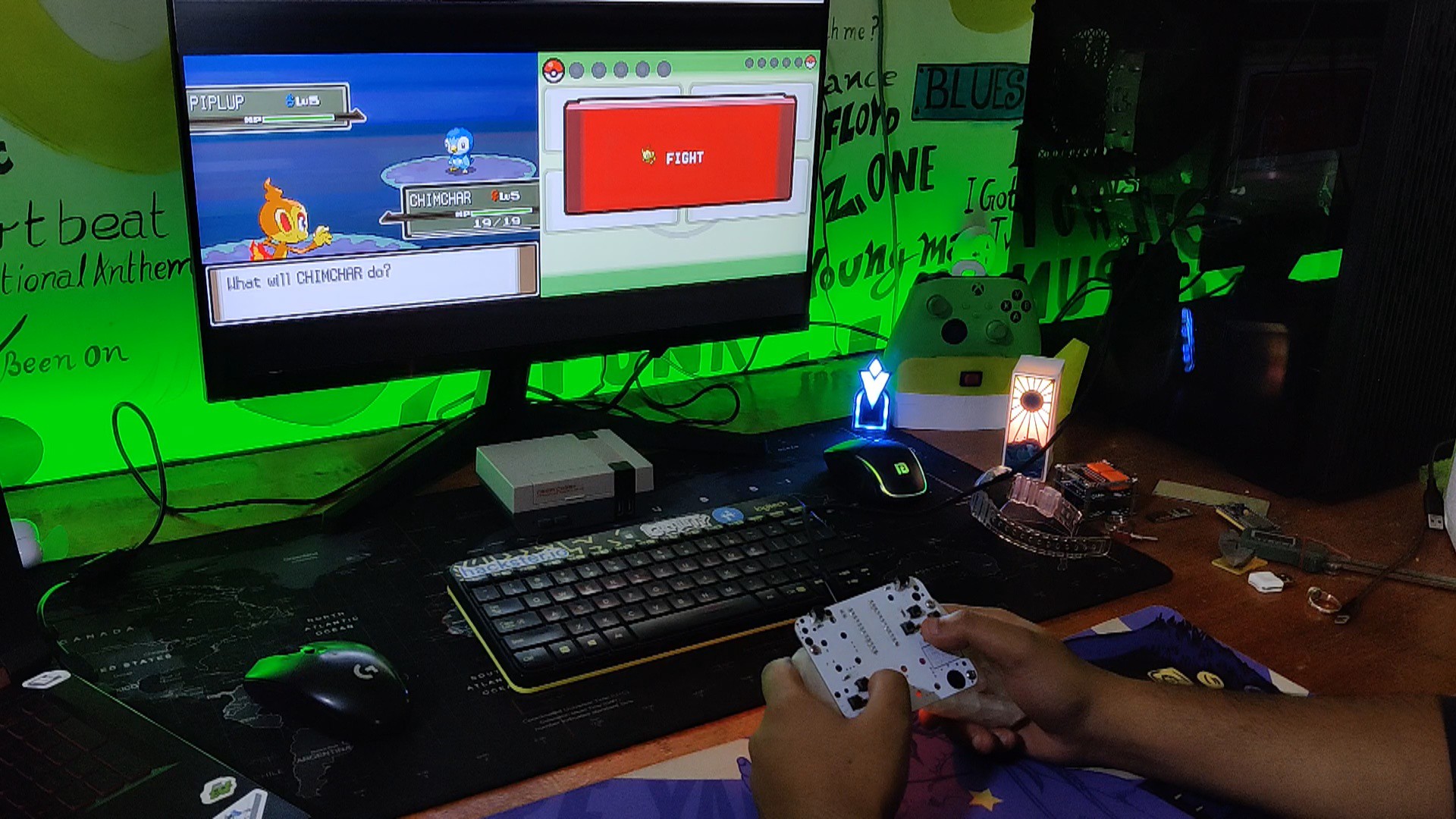
The result of this little project is a functional game controller that can be used to play retro games that do not need analog thumbsticks.
Using a PC NDS emulator, we launched Pokémon Platinum, one of the best Pokémon games ever made, to test the power of this custom gaming controller.
Prior to anything else, the button layout needs to be configured. This was accomplished by choosing the emulator controller configuration and entering the button layout in the configuration.
The controller was extremely responsive and worked smoothly.
 Arnov Sharma


Discussions
Become a Hackaday.io Member
Create an account to leave a comment. Already have an account? Log In.