 Arnov Sharma
Design
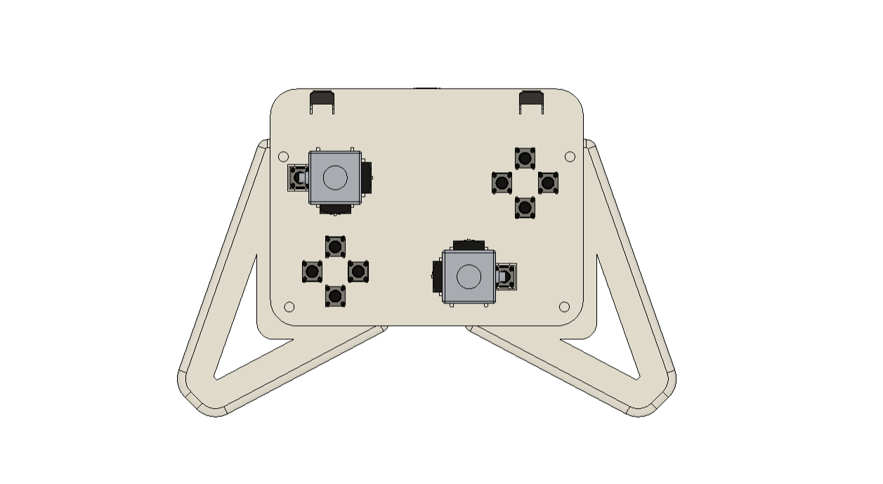

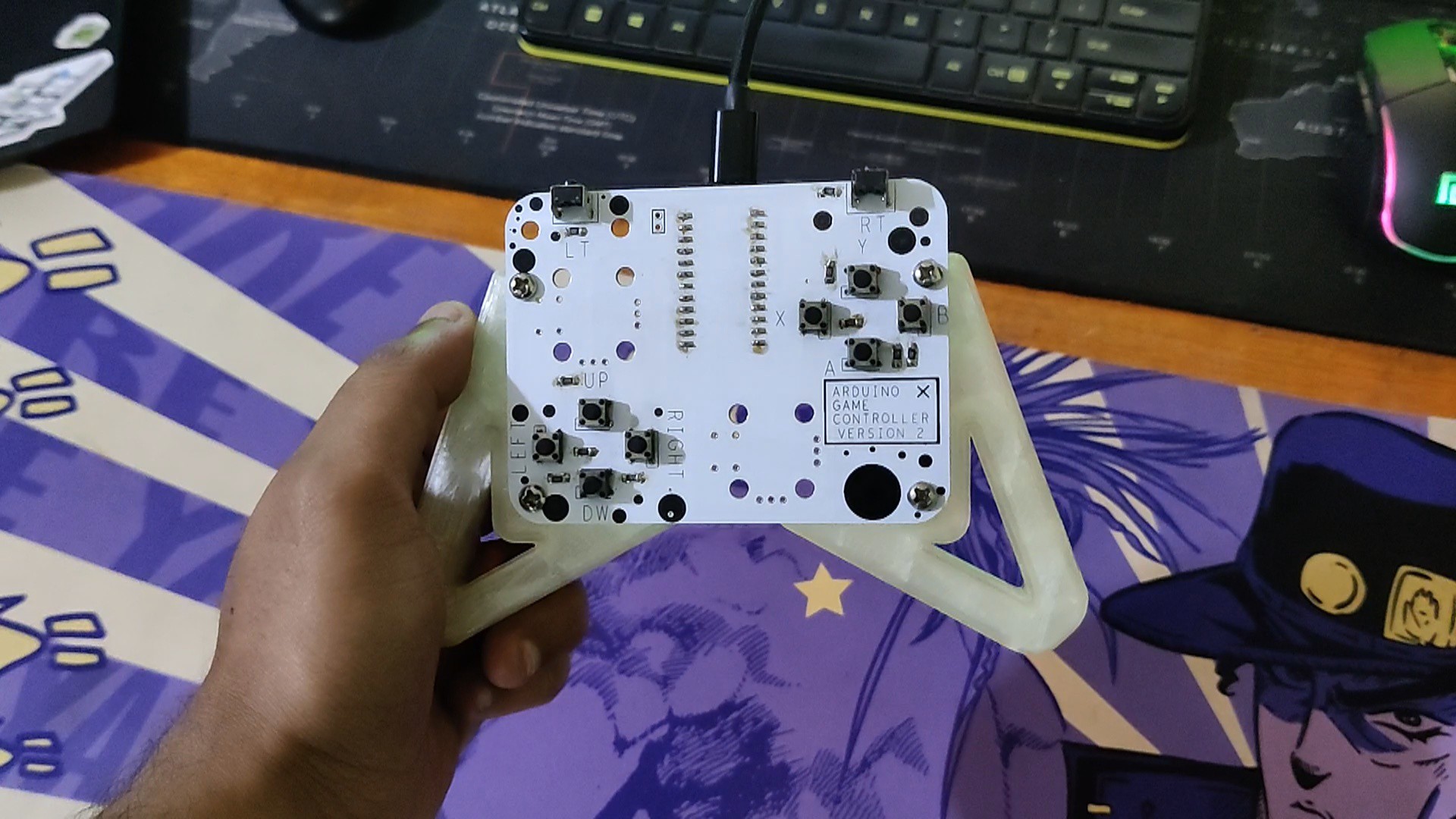
We began the project's design by drawing a basic concept that was based on the layout of a typical game controller, which has a PCB in the middle that houses all the components and two holding supports on the left and right sides.
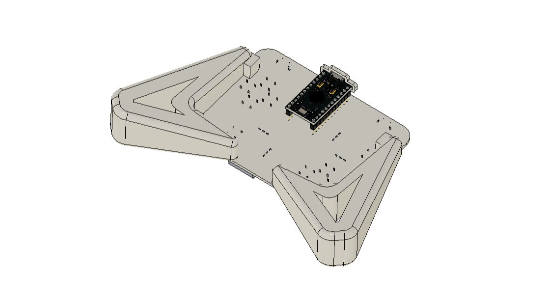
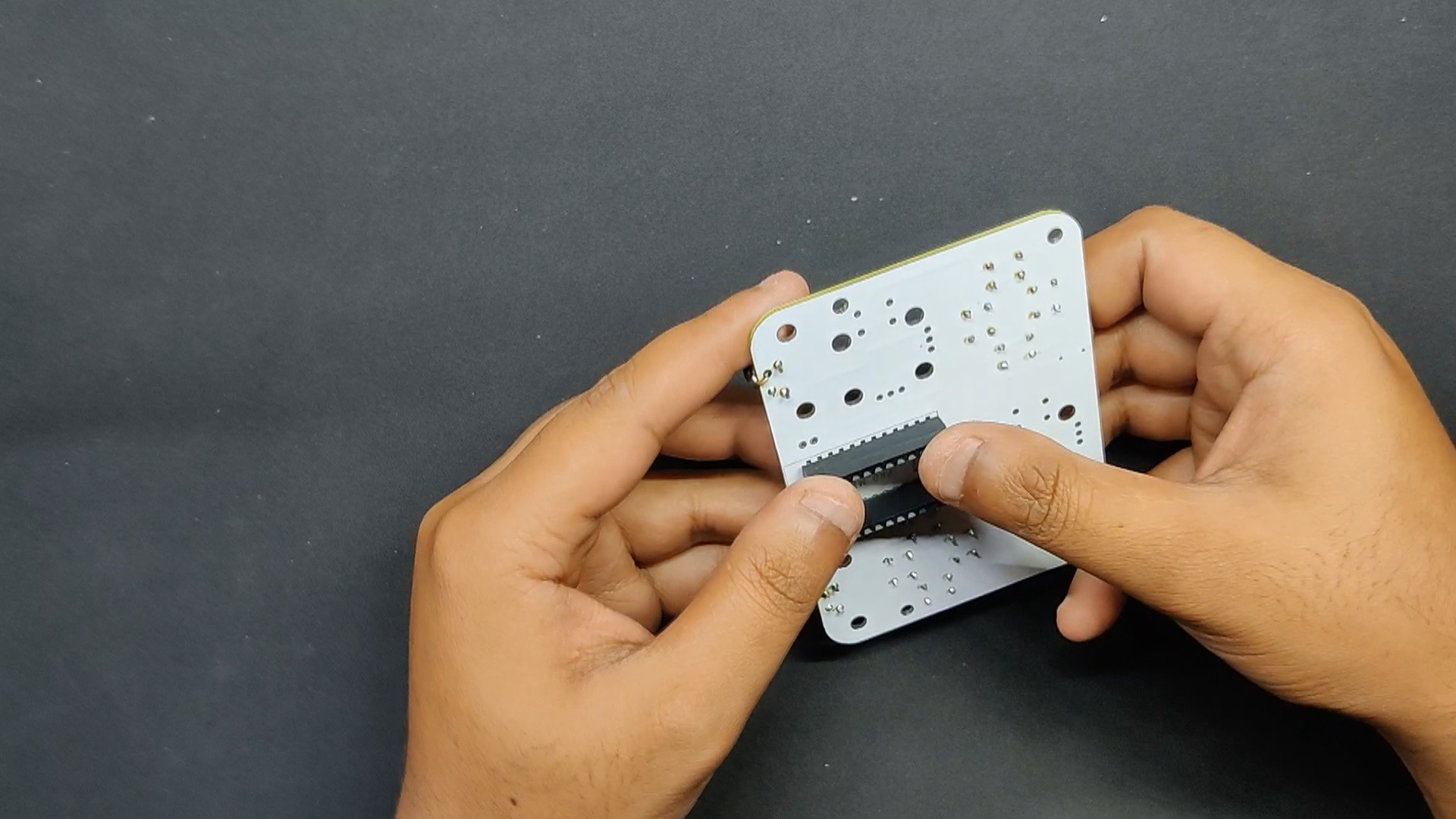
Here, we created a PCB that is attached to the circuit is the left and right handles. The Arduino Micro is located on the back side of the board, while all of the buttons are positioned on the top side.
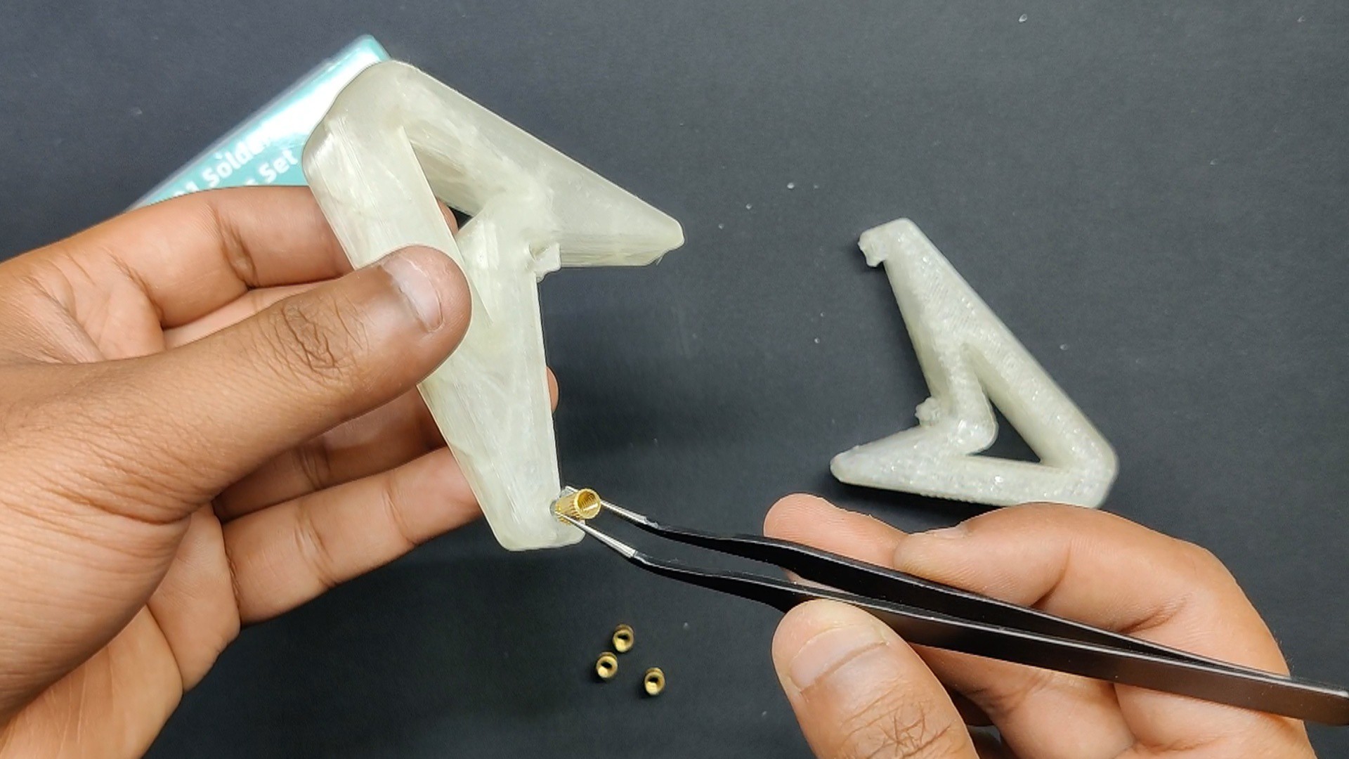
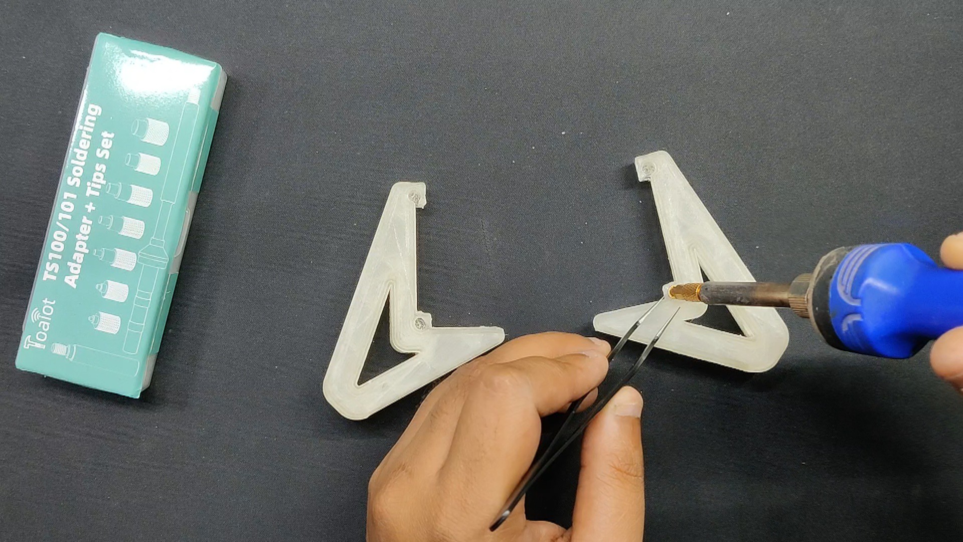
With a 0.4mm nozzle and a 0.2mm layer height, we used transparent PLA to 3D print the handle components.
Circuit


The Arduino Mini, which serves as the project's main microcontroller, is connected to 12 buttons in a particular sequential order.
Here, we constructed an arrangement resembling a voltage divider using twelve 1k ohm resistors connected in series with the button pins and VCC. The switch has resistors linked to one side and ground connected to the other.
An analog pin receives a value when a button is pressed; by reading this value, we can identify which button is being pressed. This makes it simple to integrate 10–20 buttons into a single I/O pin.
In the schematic, we have also included two thumb sticks that will be used in a future project.
Following the schematic's preparation, we made the board file and used the Cad file's layout to arrange every component correctly.
PCBWAY Service

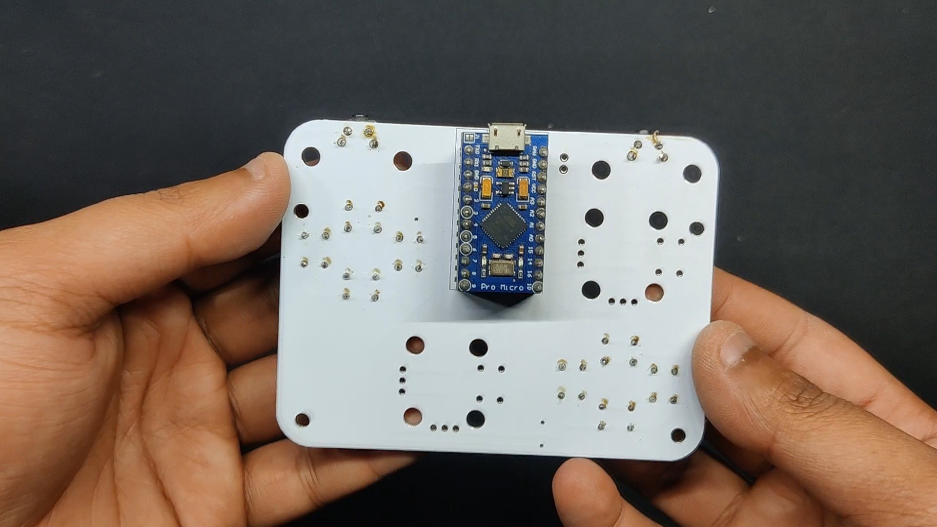
Following the completion of the board design, we ordered a white solder mask with black silkscreen and submitted the PCB's Gerber data on the PCBWAY quote page.
PCBs were received within a week, and the PCB quality was outstanding. Here, we added a few design elements on the board's silkscreen layer to increase the aesthetic appeal of the project. PCBWAY made the custom layer properly, which shows their great PCB manufacturing capabilities.
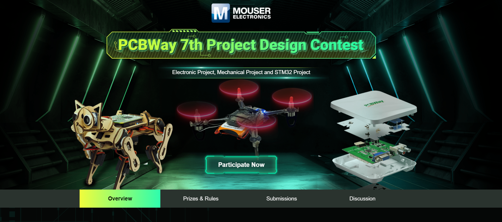
Also, PCBWay is hosting its 7th Project Design Contest, a global competition that invites electronics enthusiasts, engineers, and makers to showcase their innovative projects. The contest provides a platform for participants to share their creativity and technical expertise with the broader community.
This year’s competition includes three major categories: electronic project, mechanical project and SMT 32 project
With prizes awarded for the most exceptional designs, the contest aims to inspire and support innovation, making it an exciting opportunity for both professionals and hobbyists to gain recognition and connect with like-minded creators.
You guys can check out PCBWAY if you want great PCB service at an affordable rate.


 Michele Santucci
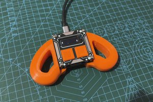
 DIY GUY Chris