Close
0%
0%

SERVOcontrol

controller board for up to 18 Servos controlled by i2c or UART

Similar projects worth following
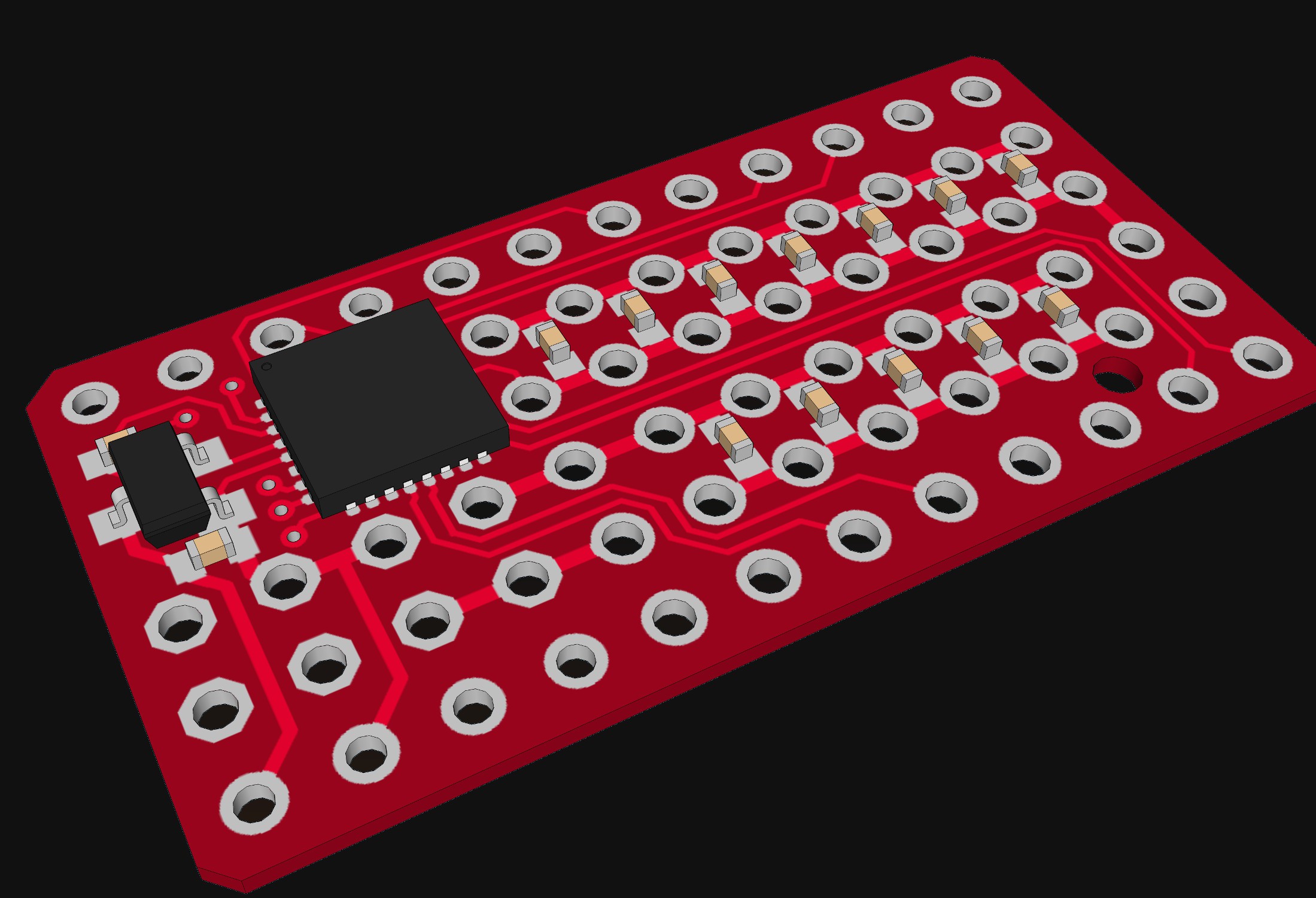
PCB with a lot of pinheaders an an small Atmel Atmega MCU to control up to 18 Servos. This will be connected via i2c and/or UART to a Master Controller (like ESP8266 or Raspberry pi), which less useful for driving servos directly.

This project is based on @Radomir Dopieralski 's #Servo Controller . I did already post something about a rebuilt of this here. But in this project I want to go further: Unlike the original project I will not only build an "shield" for an Arduino pro Mini. This will be an all in one single PCB. So no long pin headers to connect the Arduino with the other PCB.

Beside all the pin headers to connect servos to the PCB there is not much on the PCB:

  • Atmel ATmega MCU in MLF package (Atmega8 or Artmega168 do not know exactly yet)
  • Voltage regulator for the MCU (probably 5V)
  • Resonator for MCU
  • Power LED
  • Bypass Capacitors

The main motivation for this project was the frustration of my rebuilt when I tried to desoldering it again form the Arduino to change the resonator on the Arduino. And I do have enough space on a coming china PCB order left.

Future / To-Dos

This project is sadly on some kind of low piority now. So updates will be availible slowly. But here are some Ideas/To-Dos:

- finfish software and made some first Test with servos.
- fix Reset pin errata
- publish board files
- add schematic to project

Errata

- reset pin is not accessible for programming. Fix: solder wire directly to IC PA

  • 14 × Capacitor 100nF SMD 0402
  • 1 × ATmega8 or ATmegaxx8 SMD MLF
  • 1 × Voltage Regulator (5V or 3.3VV) SMD SOT23-3
  • 1 × Ceramic Resonator (6-16MHz) Murrata CSTCE
  • 99 × pin header

View all 8 components

  • Soldering

    Alex03/21/2016 at 17:25 4 comments

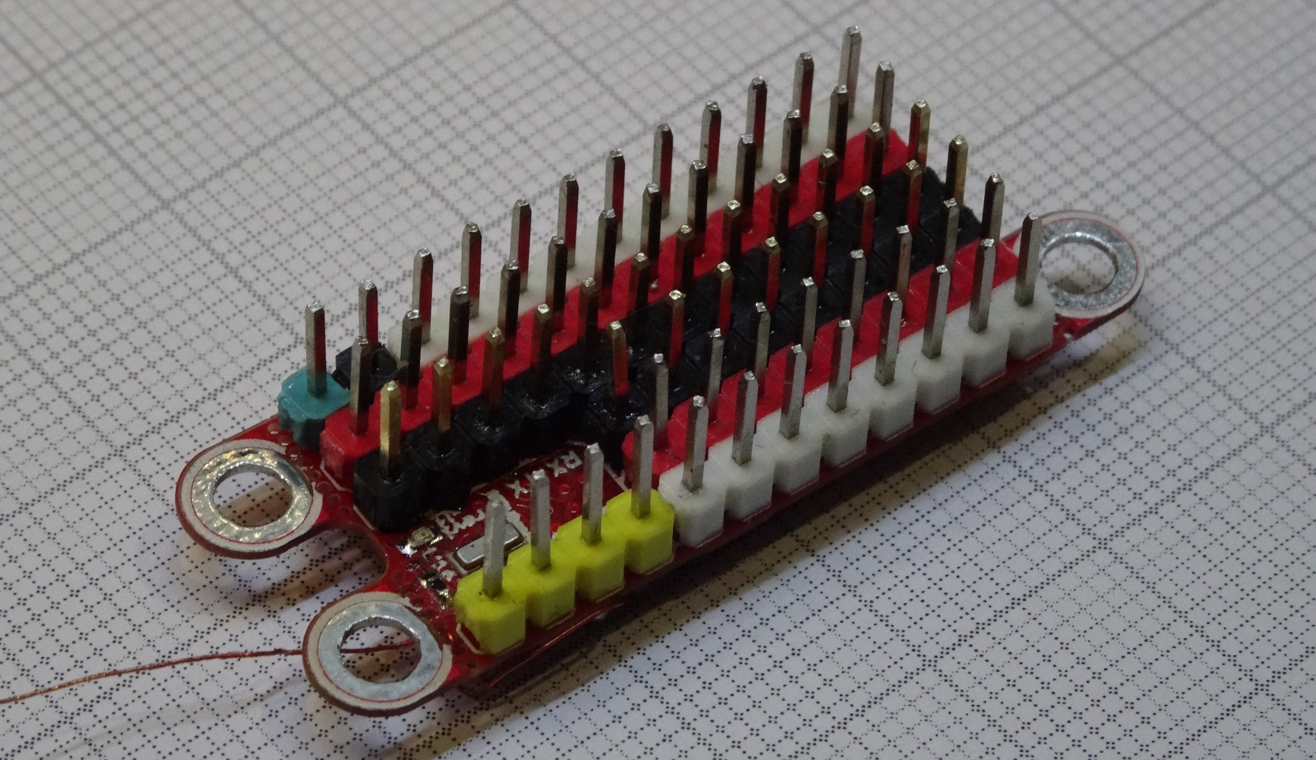
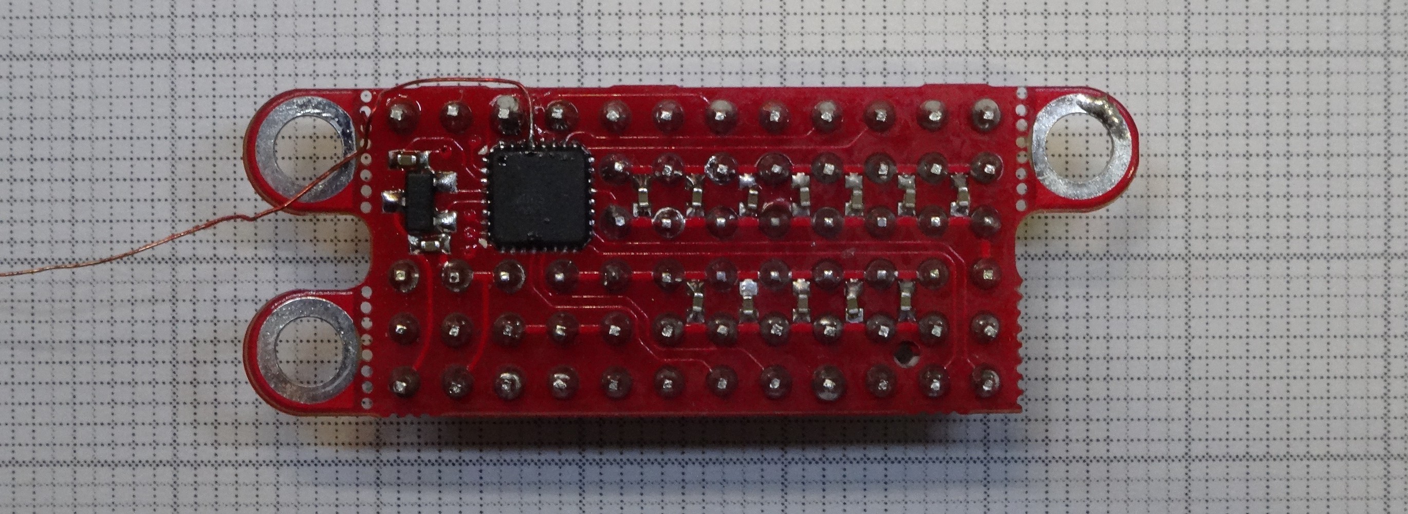
    I did had the PCBs here for some time (were on same order as my new #PICTIL PCBs). Here are some Photos of a assembled one:

    The breakable mounting holes do break off very easy. One did break of during assembling. And I did forget to put the reset PIN on a Testpad to program the IC. so I did soldered a tiny wire directly to the pad. All other Pins needed for programming are accessible over the Pin headers.

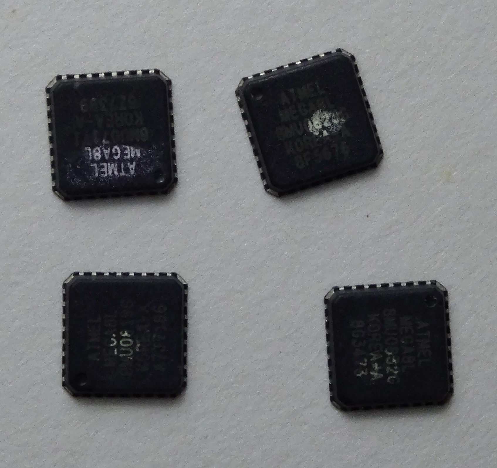
    The processor was sold as ATmega8L. But I am not sure what it is. A think it is some reused parts because the fuse settings did not had the default values and the labelling is in bad quality. The suspicious labelling:

    But at least the one soldered does work fine till now.

  • The madness goes on

    Alex02/11/2016 at 20:35 5 comments

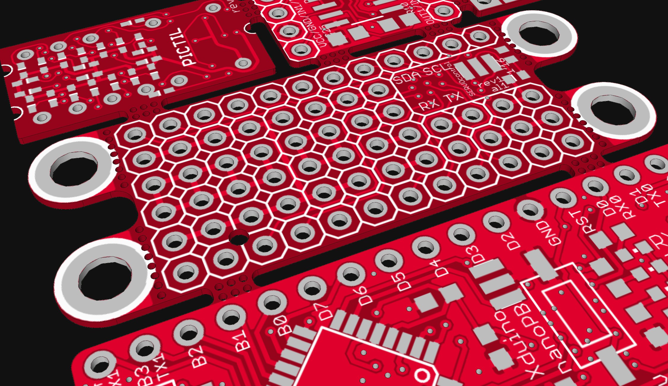
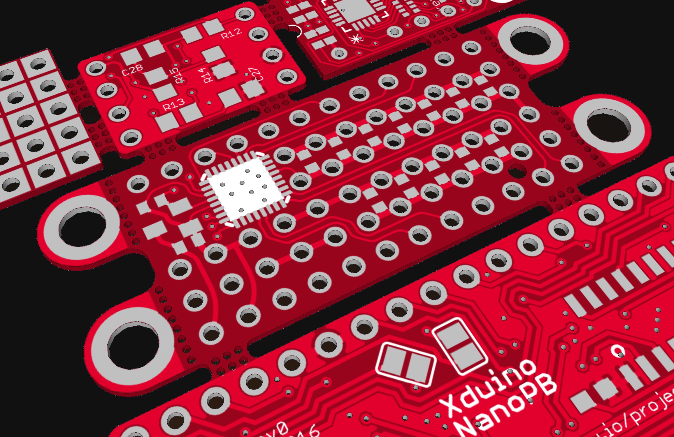
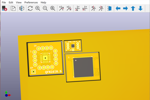
    I did finalize the PCB layout. Here are some images of the small panel I did create to fit different PCBs into a 5x5 PCB-China-order:

    I did already sent them to the manufacturer, but whole china is on holiday, so I have to be patient for the end of the new Year celebrations.

    There are also some other project I did publish here on this panel: #PICTIL and #Xduino Nano PB

  • Mountig holes

    Alex01/24/2016 at 15:04 0 comments

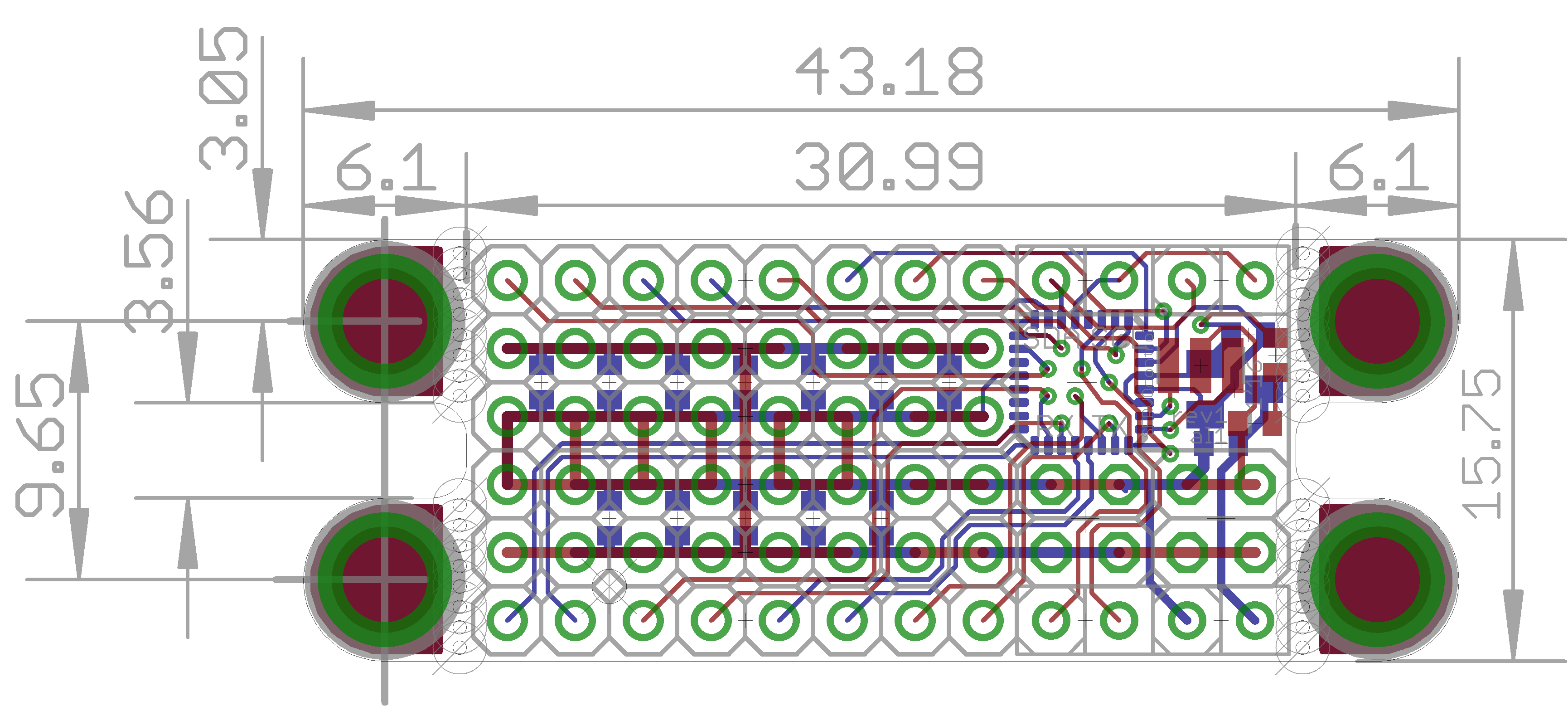
    I did add mounting holes at the sides. The holes are located on little break off tabs. If not needed the can be removed easily. The hole diameter is 3.2mm so M3 screws can be used.

    The dimensions in the image are all mm

  • First 3D-models

    Alex01/24/2016 at 12:18 0 comments

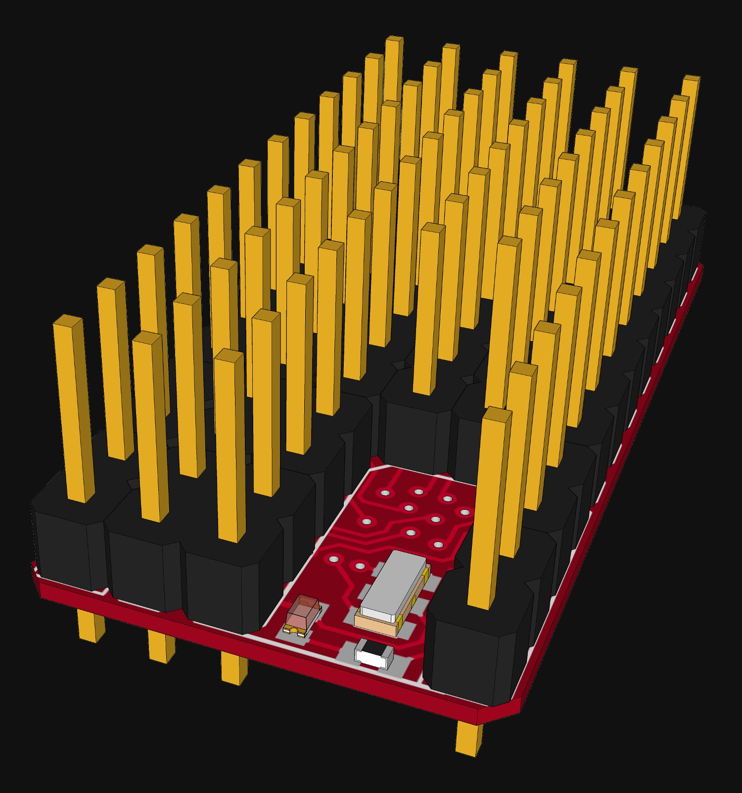
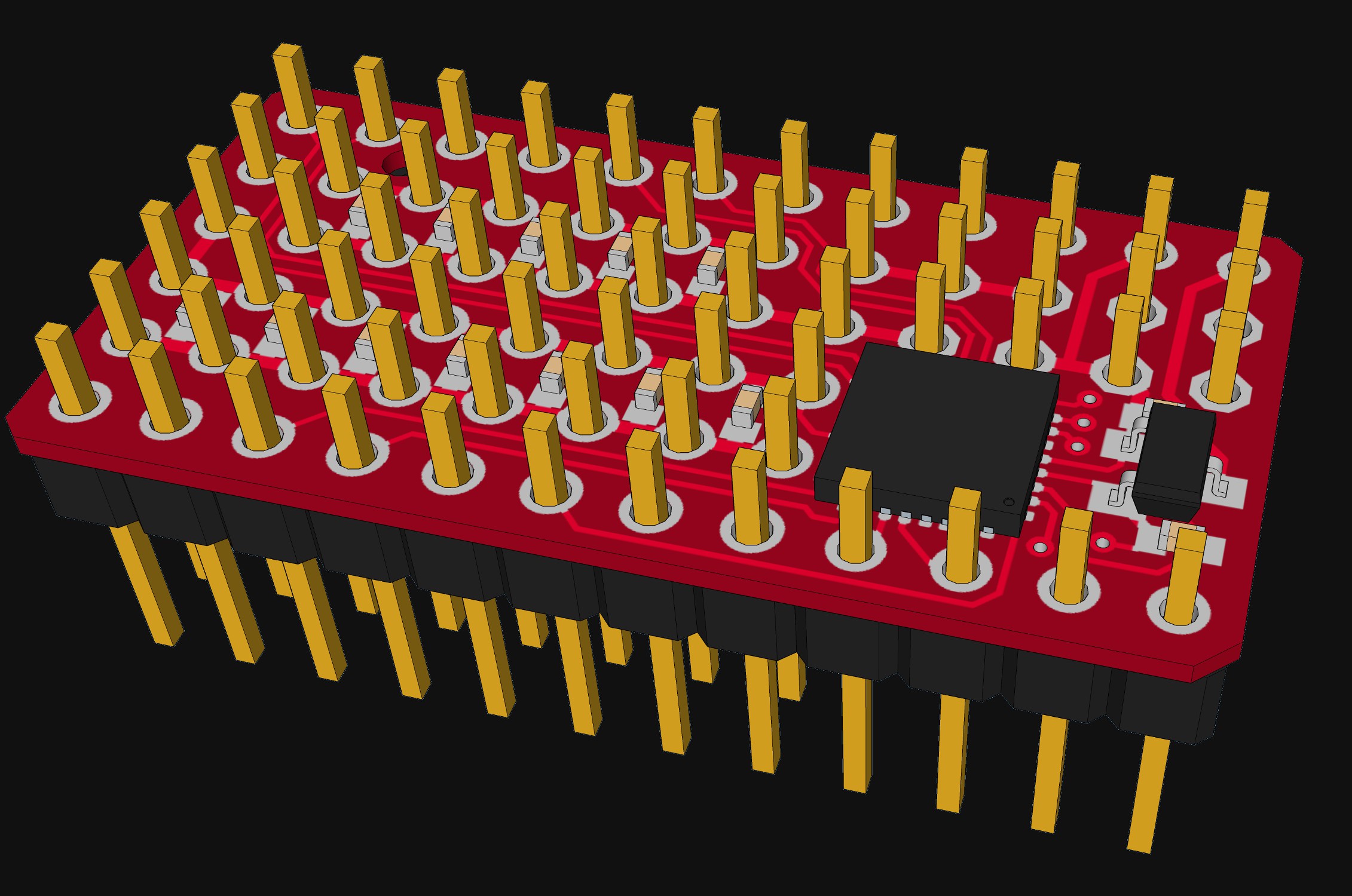
    This is what I was writing about:

    [Made with eagleUp and SketchUP]

View all 4 project logs

Enjoy this project?

Share

Discussions

f4grx wrote 12/01/2016 at 10:57 point

Nice project, I like it. Do you plan to make and sell some PCBs?

  Are you sure? yes | no

Alex wrote 12/01/2016 at 15:57 point

Thanks. So far there are no plans. Specially because this project is more on sleep-state. Evan the software is not ready yet. I will make the design files availible if you like, so that you can order your own. I do also have some of my first prototype run over. But there is at least one issue on that board. 

  Are you sure? yes | no

Roman wrote 02/11/2016 at 21:55 point

Very nice layout, looks good. Who is your manufacturer in China? It is kind of expensive to manufacture prototypes in US. I hope China is better priced.

  Are you sure? yes | no

Alex wrote 02/12/2016 at 07:25 point

Thanks,

I used dirtypcbs.com like most time. On pcbshopper.com you can also compare different international manufactures including most of the Chinese. For smaller boards I do also use OSH-Park often, they are US-Based and are faster (to Germany) than the Chinese. To the US they should be evan faster. 

  Are you sure? yes | no

Roman wrote 02/12/2016 at 18:13 point

Thanks for the info

  Are you sure? yes | no

K.C. Lee wrote 01/24/2016 at 22:18 point

You can improve access to the SMT parts for rework if you relocate the 4 header pins at the lower right corner to the left side.  Does you QFN has any exposed metal tab at the bottom side that could interfere with the vias under the package?

  Are you sure? yes | no

Alex wrote 01/25/2016 at 15:31 point

I did not do that because all the pins in the middle rows are only supply voltage pins (GND and V+). Only the outer pins are signals. This will get indicated with different colors later. The four pins I think you are talking about are signals (2x i2c-Bus). sure it would be easier for rework to move them, but for using it  I think this position is more logical. 

The QFN is actually a MLF, but yes there is a metal pad under it. In a last project I did had no problems with tended vias under a metal pad. I will give it try again. I will add some silkscreen under IC to get some more isolation.

  Are you sure? yes | no

davedarko wrote 01/24/2016 at 20:54 point

you are crazy!

  Are you sure? yes | no

deʃhipu wrote 01/24/2016 at 13:21 point

This is really great! I wonder if it would make sense to have more mounting holes, or to make the board a bit bigger to include mounting holes.

  Are you sure? yes | no

Alex wrote 01/24/2016 at 14:59 point

Thanks!

Mounting holes are a good idea. I will add them at the side, so that they can be removed if not needed. 

  Are you sure? yes | no

Similar Projects

Does this project spark your interest?

Become a member to follow this project and never miss any updates