I've started, using the links supplied, with getting an ATMega chip running on 8MHz with use of internal oscillator .Then I tested with the blink sketch to see if it worked.
Using a multimeter I checked if the solar panel was supplying voltage and I used a bench power supply to quickly supply an initial load of the supercapacitor. That is also best practice to minimize current leakage according to many websites. With the solar panel it takes a lot of time. ;-)
I'm now in the phase that I can blink an LED for minutes just using the supercap & solar configuration as shown.
Next steps are to implement power saving options as mentioned by the nice Helisoph and Nick Gammon website (URLs are delivered).
Low energy settings via Arduino sketches
Today experimented with low energy options based on suggestions from Nick Gammon's website about Atmegq328P power saving. Started directly with the ATMega 328P on breadboard with internal 8Mhz oscillator and performed some tests with power consumption using the 5V from USB PC via USB&serial converter:
- sketch A (empty sketch) 16 mA
- sketch B (sleep mode Power_Down) 375mA/ 0.35 uA
- sketch C (also brown out detection disabled) 0.35uA
- sketch D (also all analog pins defined as output with voltage LOW) 0.2uA
I didn't continue because these low current numbers are already impressive and I need to define what options are needed (analog or digital sensor, I2C or SPI?, time or event based interrupt to wake up the processor, etc.). Based on initial choice for IoT usage scenario I can continue to define settings and improve understanding of power needs.
Another solar panel
Another aspect is the solar panel, I had a small one with a Skottky diode to prevent reverse current to solar panel. I changed it for a GH165x135 solar panel where on the back of the panel I've soldered a Skottky diode 1N5819 (1N5817 is even better) and it works perfectly and gave even 6V output past the diode.
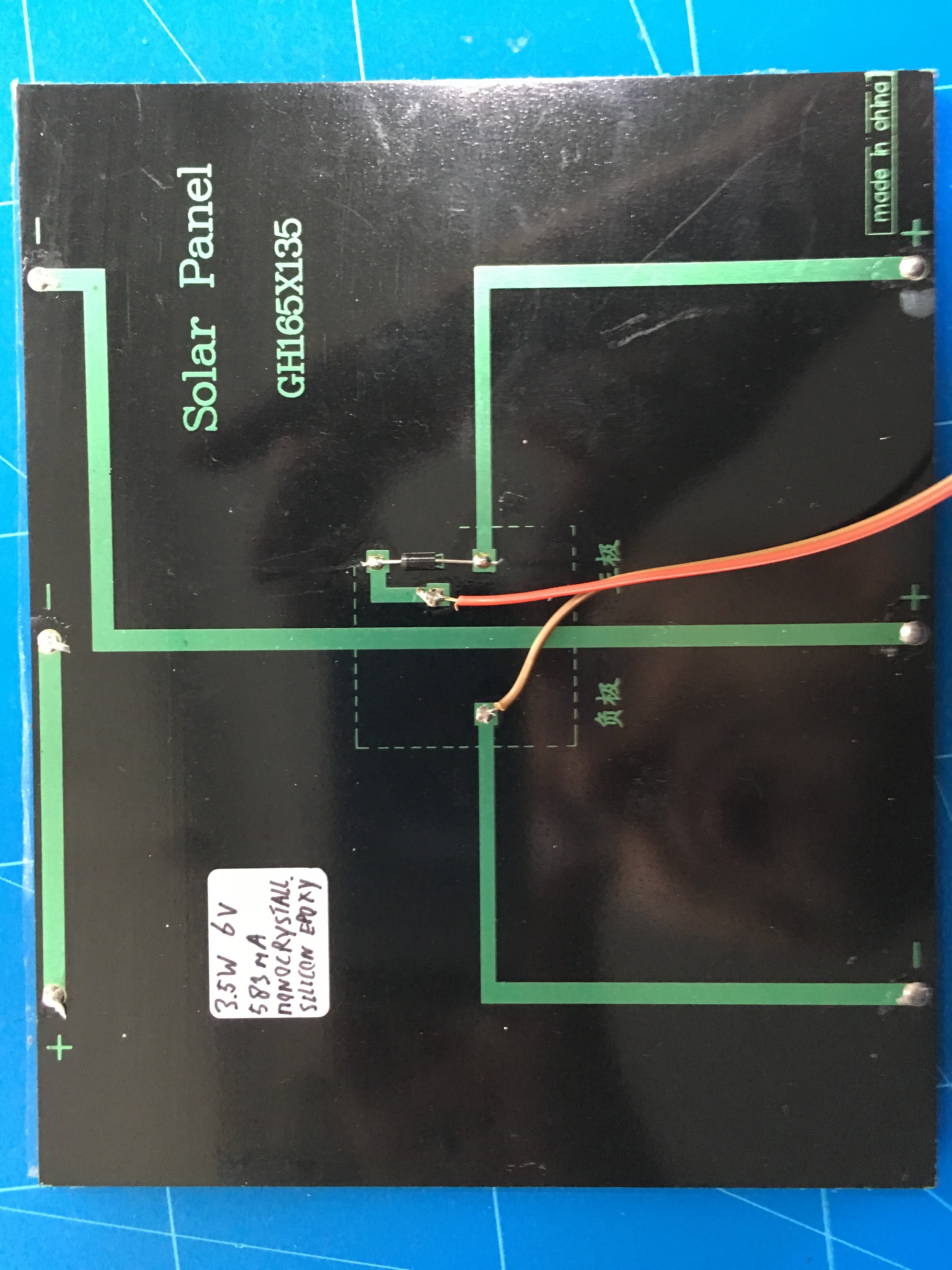
I was surprised because with the forward voltage of the diode I expected something around 5.5V which I preferred because I wanted to use it tot charge a 5.5V supercapacitor. and don't want to overcharge it.
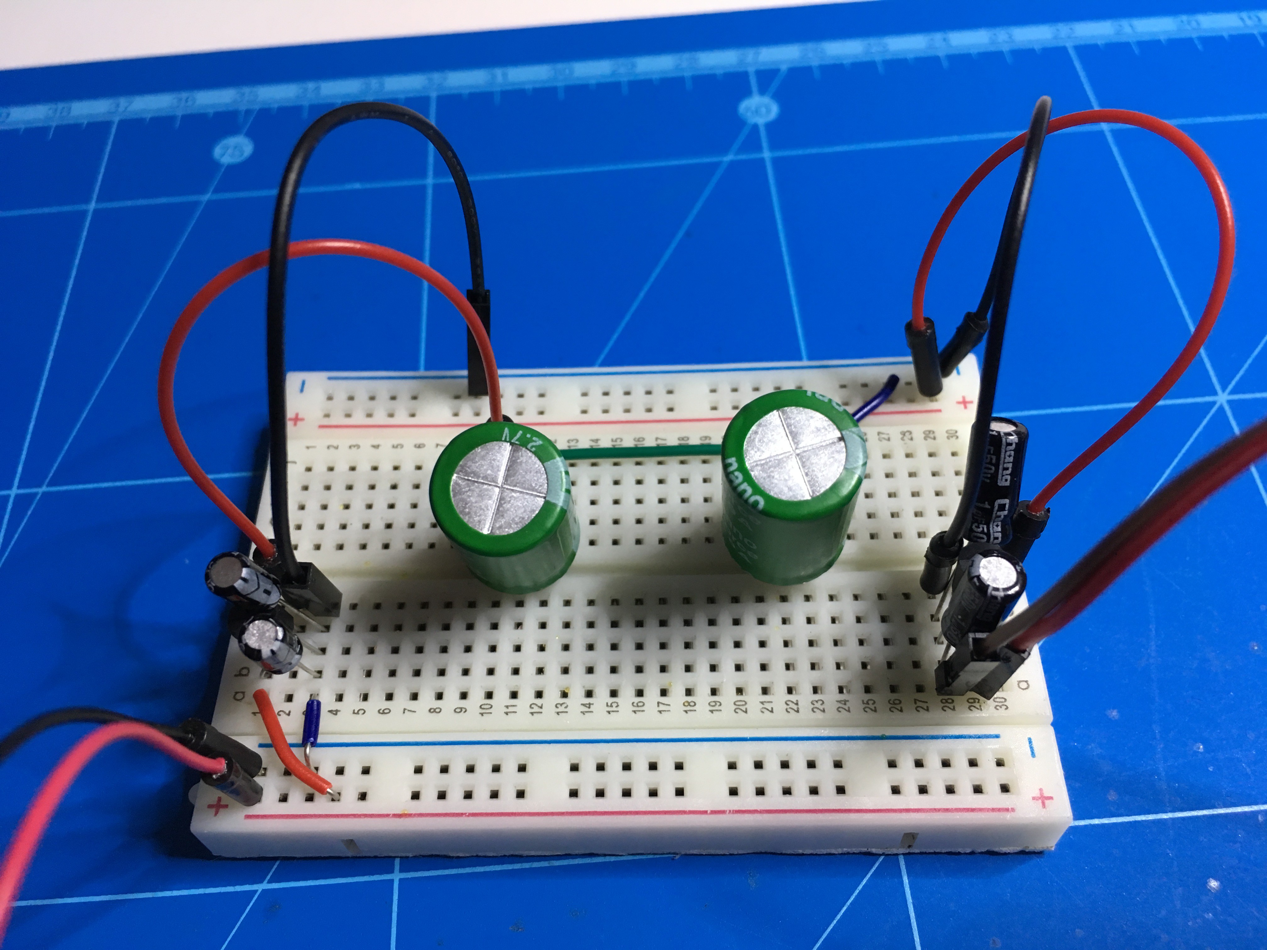
Change of plans with super caps
I've replaced the 5.5V 4F supercapacitor for two 2.7V 10F supercapacitors in series. This equals to 5.4V 5F. To avoid overcharging of the supercaps I saw some solutions using a zener diode to maximize for 5.1V but I didn't have that one. Then I used a MCP1700-5002E, low quiescent current LDO that delivers 5V for the two supercaps in parallel. Between the supercaps and the load I used the MCP1700-3302E to output about 3.3V. This is the voltage from my "power management" breadboard that I will use for my "IoT breadboard" with for now just the Atmega328P and LED for testing. In the next phase this will be replaced by sensors and a communications module. The solar power & storage solution can be improved but for now I'm happy with it.
At first I started with 2.7V 10F supercaps in parallel with the idea to run on ever lower voltages as a standard but that was to complex for me and a lot of sensor modules, FTDI USB serial converters that I have are aimed at 5V or 3.3V usage.
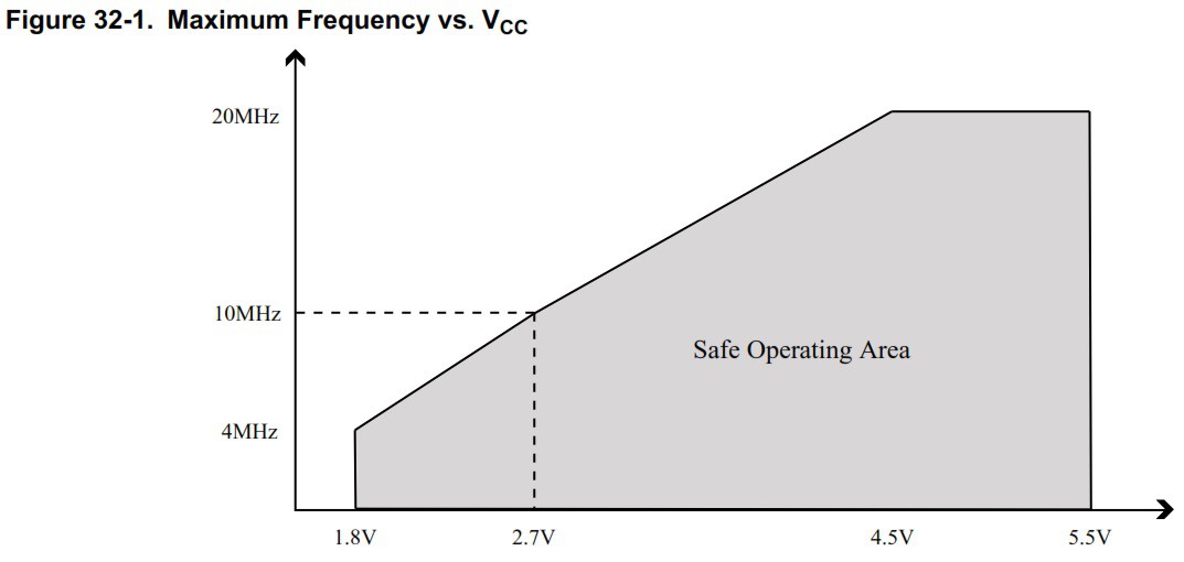
ATMega328P VCC versus frequency (from Atmel data sheet)
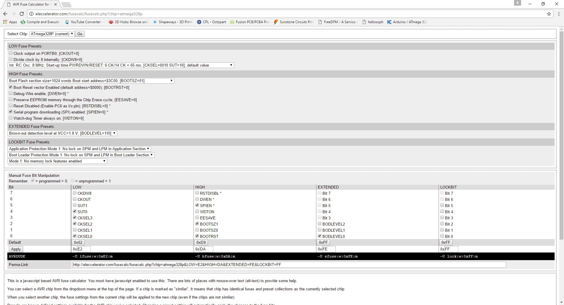
Adjusting fuse settings
I used the Eleccelerator fuse calculator to deternine the fuse settings for the 328P. The main change was enabling the brown out detection (BOD) for a minimum voltage of 1.8V. I know that enabling BOD increases the current use but I don't want to have an instable 328P that can't recover.
Using Arduino ISP as programmer, I used AVRDude via the command line:
- avrdude...

 MCenderdragon
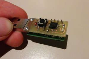
 Kris Winer
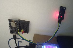
 James
James
Any suggestions for buck converter between solar panel and the two 2.7V 10F super caps in parallel? I'm looking at the DSN-MINI-360 buck converter with specs 4.75-23V to 1-17V. The small size is nice for minimizing the size of IoT solution enclosure.