 Yann Guidon / YGDES
20251112 : 258114 is the new new new modulus.
---------------------------------------------------------------
The time comes to put the theory into practice...
Log 93. New new modulo. has chosen 111110000100010001 = 254225 = 0x3E111 = 5×5×10169
which tuns into 000001111011101111 when converted for addition.
Another way of looking at it is that this gPEAC is a PEAC18x2 with an added constant of 7919=0x1EEF, but the constant is not applied all the time!
The constant can be split into 4 "segments" and the 5 MSB are a basic, simple incrementer. I know incrementers. This one is significant but still not excessive. It just means that a very small value will "hop" from LSB to b13 in 3 cycles (assuming pure Fibonacci mode) then linger for 8 cycles until reaching b16 (b17 is a bonus). 11 cycles is the worst pathological case I can create, assuming a cleared register (which is impossible), fed with a 1 word then followed with cleared words. Any attempt at "fudging" the result to make it last longer will (unlike a LFSR) accelerate the avalanche, since the MSB of the encoder is tied to 0 and there will always be a bit that can't be erased (which will then avalanche sooner or later).
I use a 2-cycle circuit, first the normal addition then the constant. I have no clue how to optimise a 3-addend circuit, though I'm sure it's possible. Leave a comment if you have relevant information. But the constant is a tentative value, because the modulo requires either the operand or the result to be kept. That's why 2 cycles are required.
- The modulo inputs are the data register, and another source that is ANDed/ORed with the constant, selected by the phase signal.
- The modulo output is a sum and a carry. The carry goes to the MUX that selects between the addend and the sum, going back to the storage register.
There is no incentive to create a dedicated constant-adder unit, unless the throughput was higher. In fact I could even quadruple-cycle the adder to compute both X and Y to save some gates but the MUXes and registers could become quite large. Maybe the shorter/simpler routing will help in turn.
There is still a nagging question : which modulus is actually better ? 254225 or 139793 ? If I built a dedicated unit, it would be harder to compare them and choose from hard data.
.
A last concern:
And what if the reduced value exceeds the modulus ? This is an error condition that should be flagged immediately, or else there is a risk of cancellation from later words. But the result further amplifies the error so it's even more easier to detect.
Adding a further comparison (another subtraction) after the reduction would be too heavy, too long, for a very rare condition. But computing the difference is not required, a binary check is enough to spot a good fraction of these errors, just looking at the binary pattern:
111110000100010001 ==> AND the 5 MSB while ORing the next cleared bits: if the OR gives 1 then there is overflow. The principle can be easily extended to the rest of the word, and the modulus has few "segments".
Here is a circuit that detects a value that is equal or higher than the modulus.
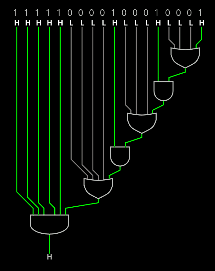
That's where the low number of "segments" also becomes advantageous.
If speed requires it, the lower segments can be omitted, but this can also be delayed by one cycle anyway.
And I have not done any NOR/NAND reduction, so the speed is still pretty good.
.
Discussions
Become a Hackaday.io Member
Create an account to leave a comment. Already have an account? Log In.