 Yann Guidon / YGDES
I have a first functional circuit in ASIC and I must write the Python code that tests the sea-of-xor.
There are 19 key values to test: 0 and the 18 single-bit-at-1 configurations.
Then throw a few "random" values for good measure, since the rest should be a linear combination of all the 18 single-bit cases, right ? And the all-ones case of course.
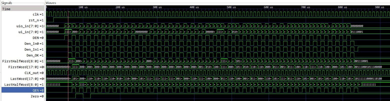
But then the results of some test vectors could become vectors themselves. So some VHDL later and we get
111111111111111111  101011111000110100
000000000000000000  000000000000000000
000000000000000001  110111011111011001
000000000000000010  110111011111011111
000000000000000100  110111101111011111
000000000000001000  110111101110011111
000000000000010000  010111100110110101
000000000000100000  110001101011001010
000000000001000000  000000011111111000
000000000010000000  101110111001000000
000000000100000000  111111000010100000
000000001000000000  111111011111111001
000000010000000000  111110111111111001
000000100000000000  111110111111110101
000001000000000000  001101111111010101
000010000000000000  000111100010110101
000100000000000000  110111000000100110
001000000000000000  111111000000101100
010000000000000000  100001001101110000
100000000000000000  000000011111111010
111111111000000000  011100010000010101
000000000111111111  110111101000100001
101010101010101010  100110111110100101
010101010101010101  001101000110010001
110111011111011001  011011011100100111
110001101011001010  000011011010101011
000000011111111010  110110111000100111
011011011100100111  101100110110001111
001101111111010101  111100010010000001
011011010110110101  011101101001011100
100100101001001010  110110010001101000
110110010001101000  101001010101001101
111100010010000001  001110001011100000
110110111000100111  101000101011111111
100110111110100101  101111000010110000
000011011010101011  100011000001110011
101000101011111111  110110010101011011
100011000001110011  101100010000011011
001110001011100000  101111110000110100
Now I must find again how Python encodes binary data.
.....
It seems to work.
excepts that it outputs MSB first.
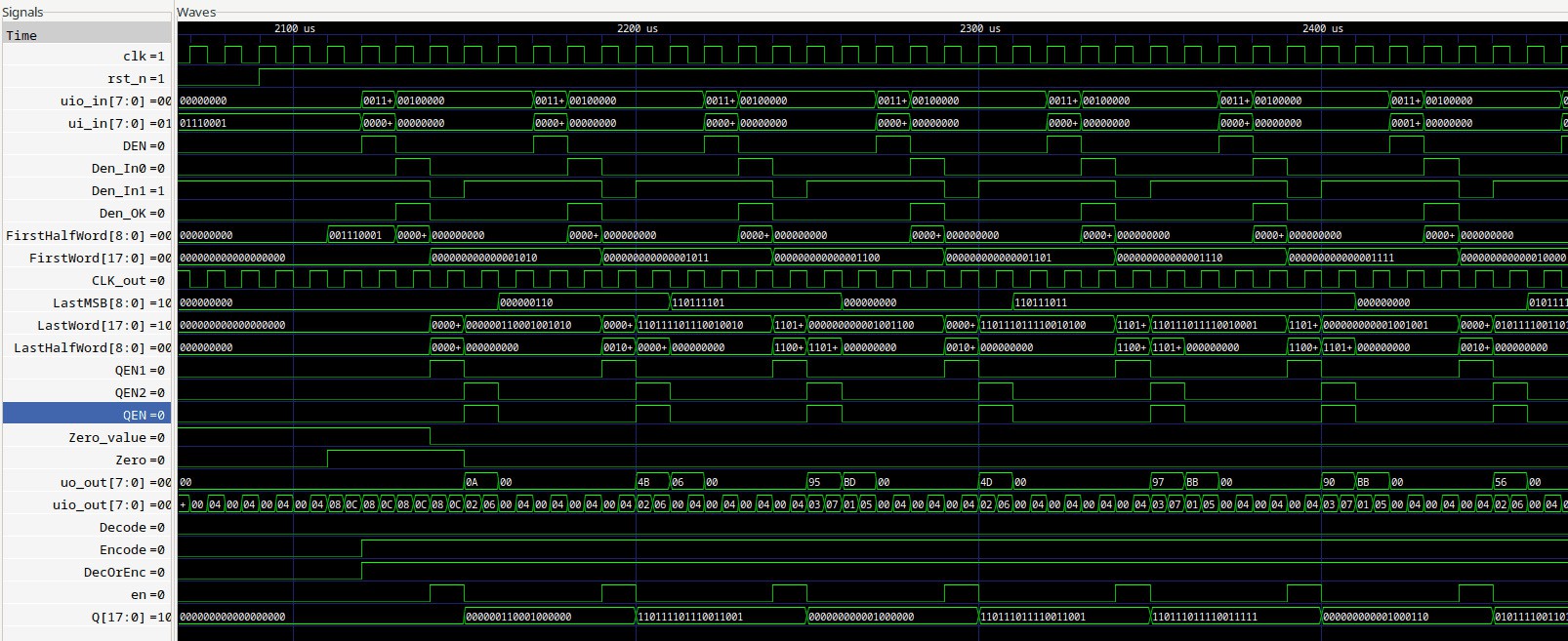
I consider making a subcircuit just to implement and test the Hammer18 in 3 modes: direct, encode and decode
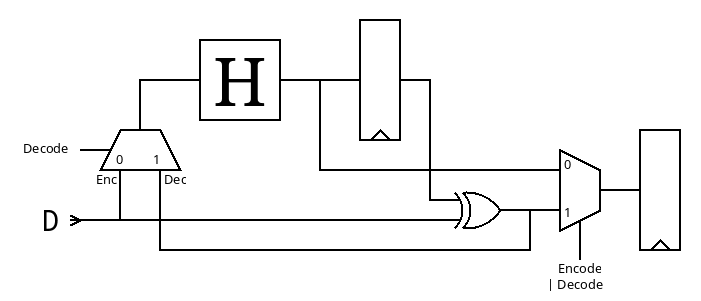
..
result : it works well.
and the current circuit uses only 22% of the tile.
Routing stats
| Utilisation (%) | Wire length (um) |
|---|---|
| 21.265 | 17366 |
Cell usage by Category
| Category | Cells | Count |
|---|---|---|
| Fill | decap fill | 1742 |
| OR | xor2 or2 | 83 |
| Flip Flops | dfrbpq dfrbp sdfrbpq | 69 |
| Misc | dlygate4sd3 | 67 |
| Buffer | buf | 66 |
| Multiplexer | mux2 | 36 |
| Inverter | inv | 21 |
| Combo Logic | a22oi | 9 |
| NOR | nor4 | 4 |
| AND | and2 and4 | 2 |
357 total cells (excluding fill and tap cells)
The speed easily reaches 100MHz, can be pushed to 200MHz,
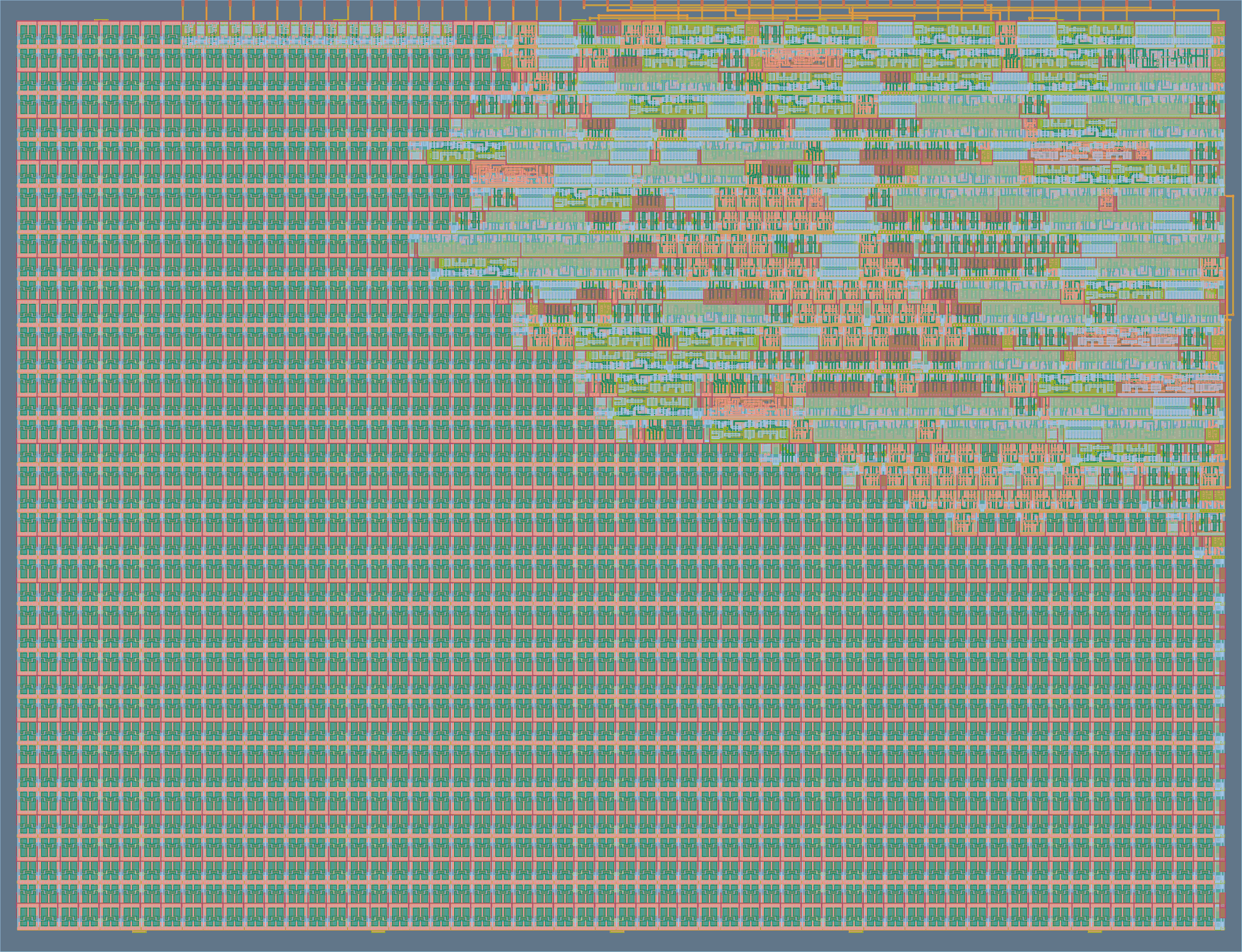
but the stats show that about half of the surface is DDFs, 1/4th is buffers/delays/fanouts, and 1/4 is logic gates...
Cell type report:                     Count     Area
Fill cell                              1742   20588.00
Buffer                                    3      21.77
Clock buffer                             23     493.52
Timing Repair Buffer                    107    1701.91
Inverter                                  9      48.99
Clock inverter                           12      65.32
Sequential cell                          69    3917.29
Multi-Input combinational cell          146    2104.70
Total                                  2111   28941.49
now, that makes you think..
Discussions
Become a Hackaday.io Member
Create an account to leave a comment. Already have an account? Log In.