So it started maybe two weeks ago when I realised that PEAC w16 could be used as more than a scrambler: Line encoding with PEAC: it's alive. and PEACLS error detection (and correction?)
There are some drawbacks though, but I have found a better scrambler system using a well-selected gPEAC: TODO: scans
So instead of using the binary PEAC w16, I use the closest Perfect to a 3x multiple:
196608 : 196605M 196598P 196594P
The ideal modulis is 65536×3=196608, the closest Perfect moduli are 196598 and 196594. You could find your own modulus in gPEAC_scans_1M.tbz if you want to play with a different width.
The idea is that each data word is scrambled by PEAC, which also provides 2 bits of "pseudo-parity" that can only take the values 00, 01 or 10. The mark 11 is used for control/framing : hence the 3x factor !
Two benefits :
- The parity is much less dependent on the MSB of the scrambled data
- The scrambling is much more thorough
One concern :
- the non-binary modulus takes another cycle to compute.
Another concern : baseline wandering.
- At the receiver end, some analog tricks could help.
- At the emitter end, forward correction could be provided by selective negation of the message, but a 3rd header bit would be required.
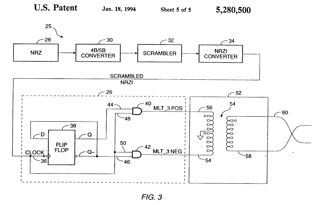
MLT-3 seems to be the way to go but I find a couple of issues with the classic method. There seems to be a driving conflict because the transformer is driven from both sides with different values, despite the center tap.

From the "transformer's rule", and as confirmed by simulations, the voltage should be equal on both sides of the tap (it's 1:1) but
* if out+ drives 1, the AND makes out- drive 0, instead of -1. and vice versa.
* if either output drives 1, the opposite -1 value gets absorbed by the ESD/clamp/protection diode !
So in either case, the transformer "shorts" one output in the +1 and -1 cases, meaning that a lot of energy gets channeled to GND.
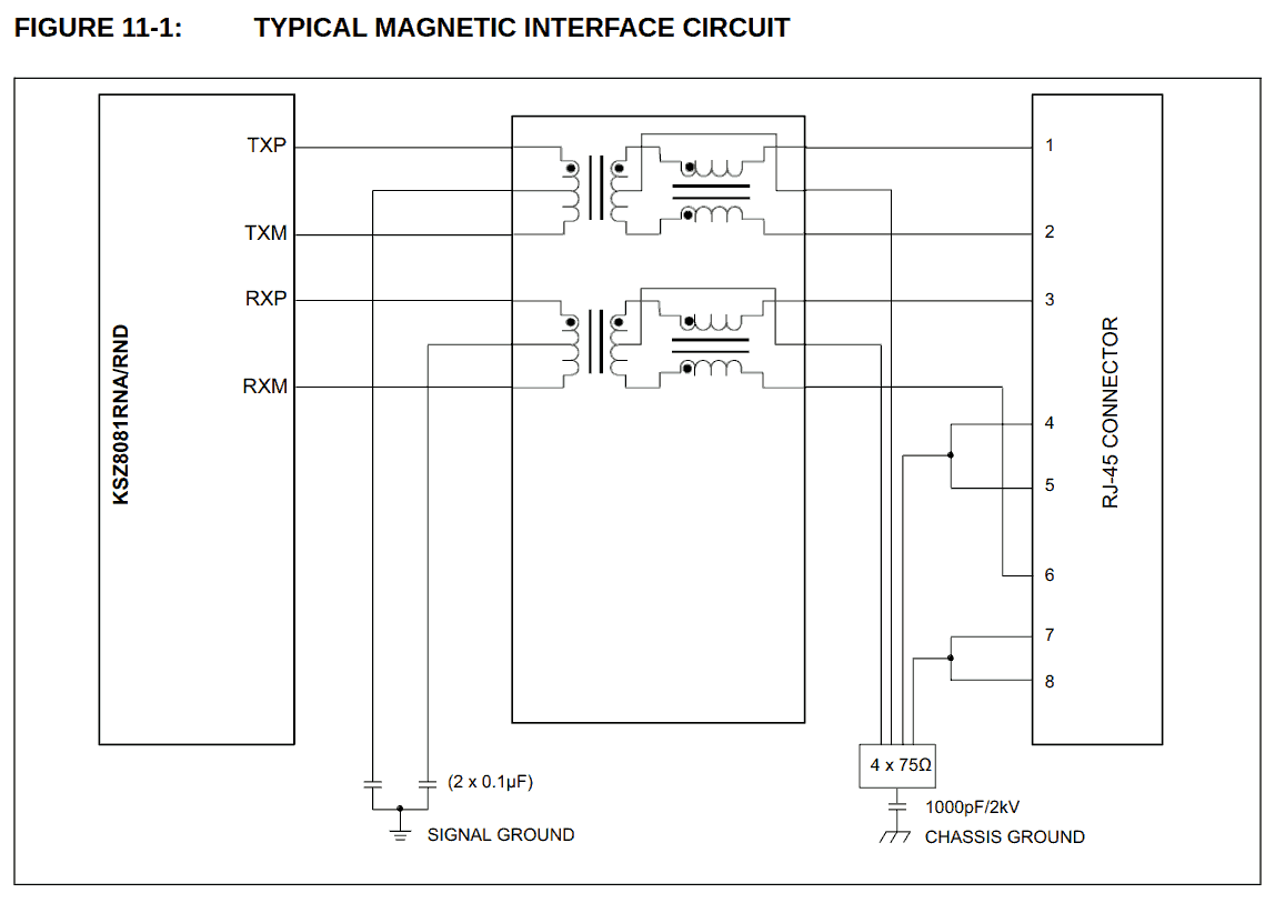
This datasheet shows that the center tap is capacitively coupled, thus helping a bit but not completely.

clamp diodes not shown...
My idea so far is to use a 2-bit quadrature counter, it's very easy to design and the 2 out-of-phase outputs can drive the transformer directly, without conflict, at the cost maybe of some sort of wiggling offset somewhere but... I'll have to test it.
Oh and since the quadrature code can go in either way, it could also encode the word's polarity/bitflip... I'm trying to explore how it could work on CircuitJS.
 Yann Guidon / YGDES
Discussions
Become a Hackaday.io Member
Create an account to leave a comment. Already have an account? Log In.