 Yann Guidon / YGDES
The system is pretty satisfying, except for one last detail.
As I'm trying to enhance the mark bits, I realise that however I turn things around, I can't detect an alteration of both CD and P, as shown above on a modified version.
The CD bit is only protected by one parity bit so it is resilient only on single-bit alterations. I can detect aggression on P/ or C/D but not both because they cancel each other.
OTOH the other bits m0 and m1 have an "expected value" (reconstructed by PEAC) so they can be compared and I can detect any other pattern of alteration, except "P/ and C/D only". Yes I can catch 3-bit and 4-bit errors thanks to the "expectations" on m0 and m1.
The only way seems to "protect" C/D by an expected value of m0 and/or m1. But that won't solve everything, particularly compared to other signals that have an avalanche factor up to 5 !
Then it becomes clear that the mark-parity block (with only 3 input signals) is "lonely" while the others are merged to share avalanche. So I have to find a way to connect them.
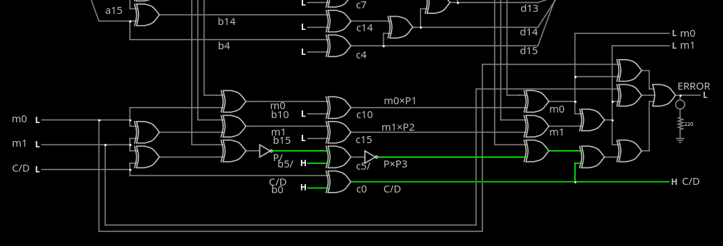
Current circuit is here. The three merged 6/7-wide Gray parity blocks are separate from the 3/4-wide mark block, on which the rest acts as an "aggressor" that must be undone before the mark can be recovered.
The "merge" of the mark block uses 2+2 more XORs and adds one gate of latency at the decode stage.
I tried a little subtlety by crossing the connections :
- m0 XORs the group that then "aggresses" C/D later
- C/D XORs the group that alters m0.
This way, all the signals are interdependent and any alteration of C/D will go around and come back at the big error OR3 through the m0 parity. The problem is that the order of the operations makes it impossible to recover/decode the values pre-aggression. I must find something else.
---------------------------
Alterations of C/D are bound to happen, and they are taken into account in the protocol's design.
Changing C/D from 1 (control) to 0 (data) is detected at 3 levels:
- the m0/m1 values do not match 75% of the time
- the altered values are convolutionally processed by PEAC and they will alter m0/m1 as well as the checksum
- the new data word will change the size of the datagram, which is determined in advance. More or less data will trigger a protocol error.
But the C/D word does not have this depth so I'm pretty miffed that a simple double-bit flip can disrupt the control. Should the m0/m1 implement a sequence number as well for the control words, on top of the parity ?
---------------------------
Back on the drawing board, I try to simplify the big mess of wires, and reorganise the signals.
First step: the whole architecture is streamlined and built around 3 blocks with 7 or 8 in/outputs. That's 22 signals but I will merge them from all 3 ends. That's because 16+3=19 = 6+6+7, each block with a shared signal so 7+7+8 it is. Here is the 7-bit block and 8-bit block.
The decoder is deeper (4 gates now) but this might be compensated by a simpler decoder somewhere else. The "V" is asymmetrical so there might be something with odd/even parity, maybe, I'll see.
Second step: the 3 merged "sides" are assigned to C/D, m0 and m1. This creates the most avalanche in case of alteration and these signals are transmitted "in clear", easily/immediately recovered.
Third step: I'll figure out how to deal with the mark bits and the parity...
.
.
Discussions
Become a Hackaday.io Member
Create an account to leave a comment. Already have an account? Log In.