 Yann Guidon / YGDES
Early test show a curious pattern:
ghdl -a $VER GrayParity17_pak.vhdl test/test_GrayPar17.vhdl &&
 ghdl -e test_graypar17 && ./test_graypar17
   ~~~ Testing GrayPar17 ~~~
i: 0 in: 0:0000000000000001 enc: 00000011110000000010
i: 1 in: 0:0000000000000010 enc: 00100001110000100000
i: 2 in: 0:0000000000000100 enc: 00000101110000001001
i: 3 in: 0:0000000000001000 enc: 01001001110000010000
i: 4 in: 0:0000000000010000 enc: 00000001010000100000
i: 5 in: 0:0000000000100000 enc: 00000101110100000000
i: 6 in: 0:0000000001000000 enc: 00000000110000001000
i: 7 in: 0:0000000010000000 enc: 00001001110001000000
i: 8 in: 0:0000000100000000 enc: 00000001100000010000
i: 9 in: 0:0000001000000000 enc: 00000011110010000000
i:10 in: 0:0000010000000000 enc: 00000001010000000100
i:11 in: 0:0000100000000000 enc: 00000001110100000100
i:12 in: 0:0001000000000000 enc: 00000000111000000000
i:13 in: 0:0010000000000000 enc: 00000001111001000000
i:14 in: 0:0100000000000000 enc: 00010001100000000000
i:15 in: 0:1000000000000000 enc: 00010001110010000000
i:16 in: 1:0000000000000000 enc: 10100001110000000010
This "column" is caused by a curious set of circumstances.
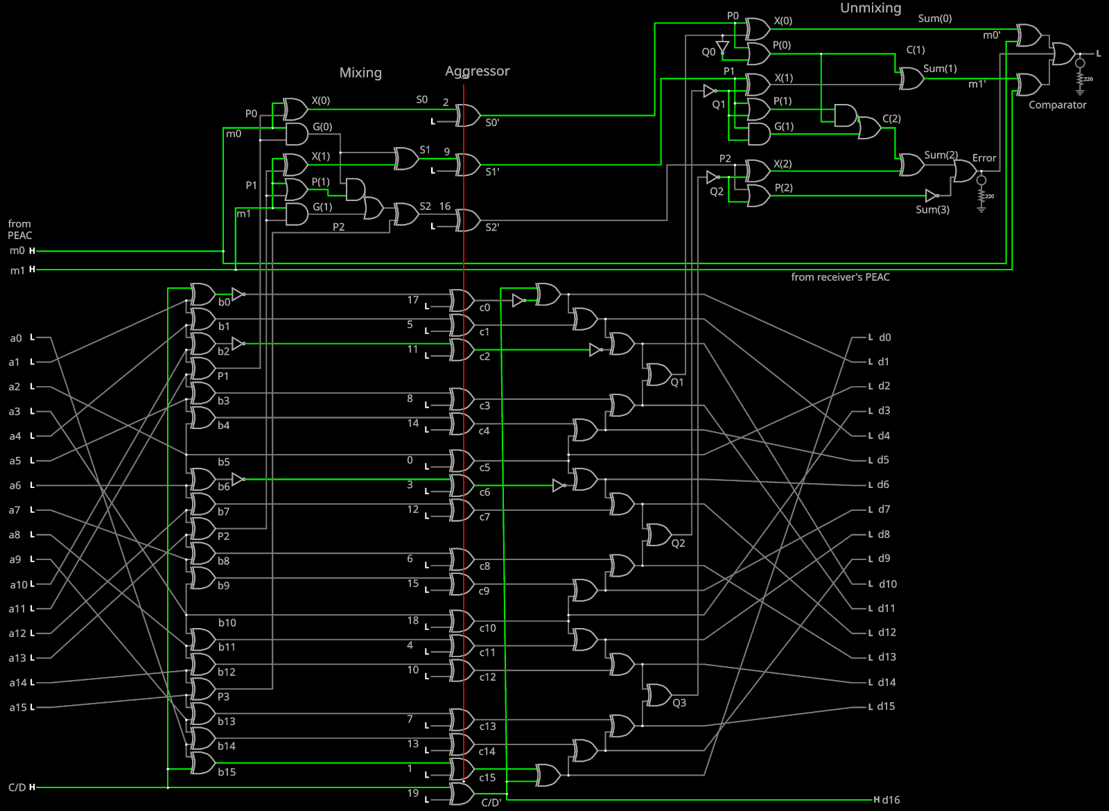
The 1s are caused by the negated XORs: I added a triplet of NOTs "just in case" so they are not strictly required (after all we have the gPEAC scrambler for this very purpose) but they could help a bit in case of uniform value (all-1s or all-0s).
I had put them in places that looked "good", not close to each other and at the middle of the slopes of each V. One NOT per V, so that's 3 inversions, to provide odd parity. It should have appeared scattered through the word.
And then, I added the two layers of shuffling. This totally reversed the desired effect!
Now I should move the NOTs according to the actual index in the 20-bit word, instead of the geometry of the Gray decoders. I am not sure whether they should be kept, but they cost nothing and, before I switched to PAM3, they would have been extra-useful to recover the clock with NRZi.
---
I moved the NOT to indices 3, 11 and 17 (c0, c6 and c2). This creates an odd parity on only one group.
i: 0 in: 0:0000000000000001 enc: 00100010100000001010
i: 1 in: 0:0000000000000010 enc: 00000000100000101000
i: 2 in: 0:0000000000000100 enc: 00100100100000000001
i: 3 in: 0:0000000000001000 enc: 01101000100000011000
i: 4 in: 0:0000000000010000 enc: 00100000000000101000
i: 5 in: 0:0000000000100000 enc: 00100100100100001000
i: 6 in: 0:0000000001000000 enc: 00100001100000000000
i: 7 in: 0:0000000010000000 enc: 00101000100001001000
i: 8 in: 0:0000000100000000 enc: 00100000110000011000
i: 9 in: 0:0000001000000000 enc: 00100010100010001000
i:10 in: 0:0000010000000000 enc: 00100000000000001100
i:11 in: 0:0000100000000000 enc: 00100000100100001100
i:12 in: 0:0001000000000000 enc: 00100001101000001000
i:13 in: 0:0010000000000000 enc: 00100000101001001000
i:14 in: 0:0100000000000000 enc: 00110000110000001000
i:15 in: 0:1000000000000000 enc: 00110000100010001000
i:16 in: 1:0000000000000000 enc: 10000000100000001010
It's less clustered now. But I have to update the circuit diagrams etc.
Looks great so far.
Discussions
Become a Hackaday.io Member
Create an account to leave a comment. Already have an account? Log In.