 Yann Guidon / YGDES
The last log 65. GrayPar17 has identified one reason why the parity check failed for many unexpected cases.
A proper interleave goes a long way but the combination with XOR exposes a flaw: XORing any pair of the 3 signals does not change the parity, so the parity error is not detected and we're left with the 1/4 odds of getting the right m0/m1 value. Is there a coding space where it's not the case? Unlikely.
Standard addition might help, but it's still a bit too linear. Playing with the carry input may help, when in fact it only shifts the problem. And I'm frustrated since the last circuit couldn't catch all 1-bit and 2-bit (consecutive) errors despite 3 bits of protection.
Checking with a table: binary addition has 1 odd in 2 to change the parity of the result and there is no clear pattern. I'm not sure there exists a coding space that behaves as I want, in the end there is only one parity bit worth of immediate detection capacity. I would need a second parity bit and we're already out of budget, since gPEAC will catch everything else.
Binary addition could still work well, smoothing the statistics. The point here is "giving a fighting chance" to detect problems. Furthermore, the carry generated during one cycle could be reused in the next cycle, making the system a basic convolutional code.
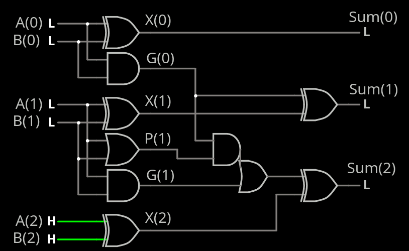
I have designed an 8-bit adder made of 3-input gates for the #YGREC8 project, it will help here. No idea if/how I can turn it into End-Around-Carry and whether it will make things better. At least I must try a couple versions and compare the stats.
The resulting simplified circuit still has one cancellation spot at the MSB, hence the advantage of End-Around-Carry in this case.
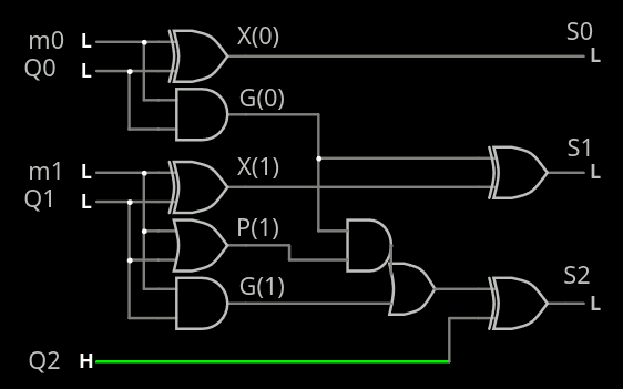
But it is still "simple enough", adding only 2 gates to the critical datapath, so let's try it.
And it could get simpler, if we consider that one of the signals is the XNOR of m0 and m1. So in fact we only really need to add 2 bits to 3 bits, which rids us of one cancellation place if B(2) is kept 0. Which also makes us realise that we're not really adding 3 bits after all !
The new circuit saves 2 XOR for the encoder because we simply drop the parity step, thus reducing the operand size.
This moves the complexity to the decoder, which has to implement a subtract to recover m0 and m1. And we can detect errors if the subtraction underflows.
-\+  0  1  2  3  4  5  6  7
0    0  1  2  3  4  5  6  7
1   -1  0  1  2  3  4  5  6
2   -2 -1  0  1  2  3  4  5
3   -3 -2 -1  0  1  2  3  4
4   -4 -3 -2 -1  0  1  2  3
5   -5 -4 -3 -2 -1  0  1  2
6   -6 -5 -4 -3 -2 -1  0  1
7   -7 -6 -5 -4 -3 -2 -1  0
The bold results are errors, 5/8th of the results can be detected as bad.
-\+          0    1    2    3    4    5    6    7
  n   ~n
0000 1111  0000 0001 0010 0011 0100 0101 0110 0111
0001 1110  1111 0000 0001 0010 0011 0100 0101 0110
0010 1101  1110 1111 0000 0001 0010 0011 0100 0101
0011 1100  1101 1110 1111 0000 0001 0010 0011 0100
0100 1011  1100 1101 1110 1111 0000 0001 0010 0011
0101 1010  1011 1100 1101 1110 1111 0000 0001 0010
0110 1001  1010 1011 1100 1101 1110 1111 0000 0001
0111 1000  1001 1010 1011 1100 1101 1110 1111 0000
So if any of the 2 MSB is set, it's an error.
Now it's a matter of transforming the classic adder and simplifying it with the constant values.
Starting from the old 8-bit adder, I set C and X3 to 1 and I get this circuit:
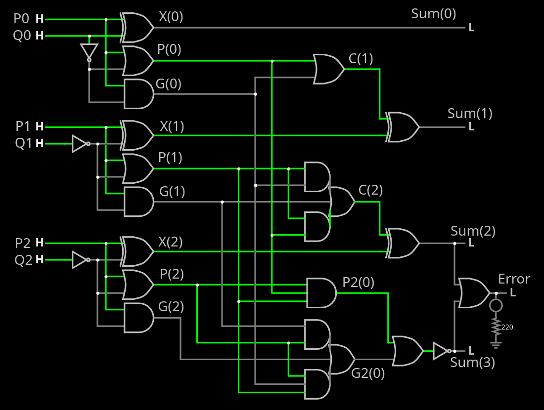
The critical datapath is longer but this circuit can be run in parallel with gPEAC.
Both units are integrated in the new circuit.
Now it's time to convert it to VHDL and compare with the basic XOR method.
------------------
Aaaand VHDL says there's an error with the error. An error that doesn't manifests in the circuitjs sim. "Test early, test often, test everything!" but it's still promising.
Wait, I messed with some copy-paste and found the error in the 1st layer of P&G.
But to my surprise :
Q2n := not Q2;
X2  := R2 xor Q2n;
P2  := R2 or  Q2n;
G2  := R2 and Q2n;
works just as well as
Q2n := not Q2;
X2  := R2 xor Q2n;
G2  := R2 or  Q2n;
P2  := R2 and Q2n;
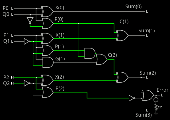
So I set G2 = P2 = R2 or Q2n and G22 disappears. And P22 disappears too !
This gives this simplified circuit:

which is pretty impressive if you hadn't thought about it before. But wait, applying these same principles, C1 and C2 get simplified too! Now look, with only 13 gates, this smaller circuit is looking less scary than before:
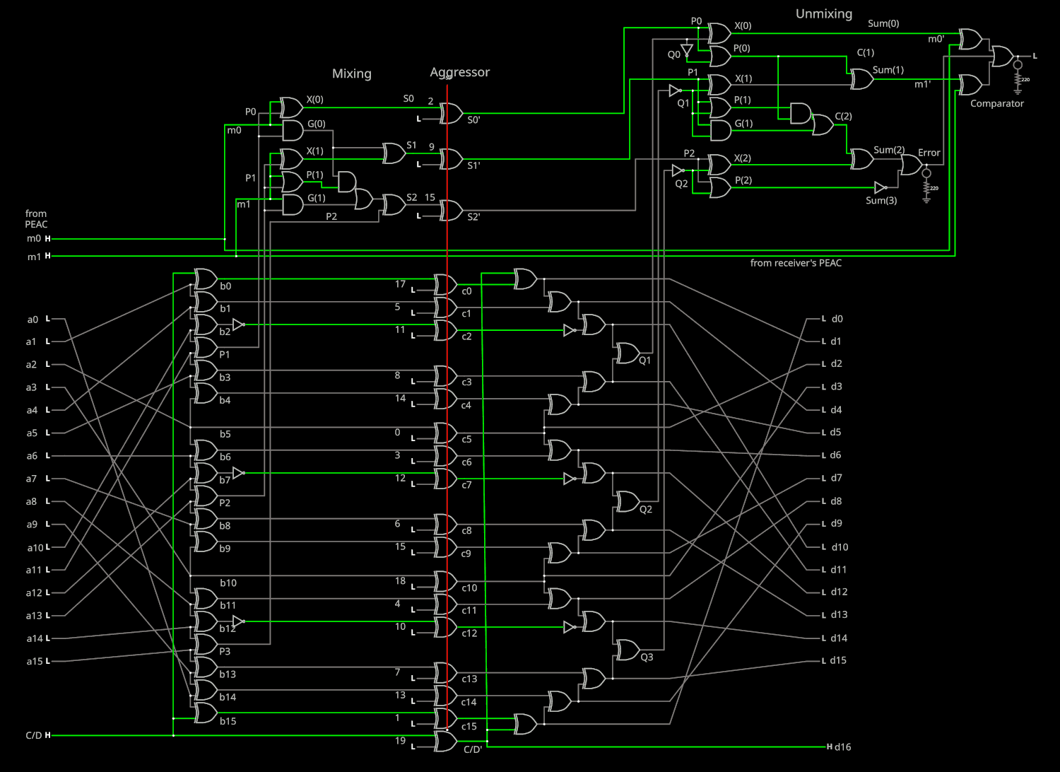
So here it is integrated in the whole circuit, this link is reaching the limit of URL sizes though...
The gate count has decreased a bit but not the latency.
And the error rate is perfect:
   ~~~ Testing Add3+Sub3+errors ~~~
 attempts:224
  blocked by Sub3:146
  blocked by cmp:78
  passed anyway:0
Meaning that no error that is injected either at the markers or the data field can be missed (m0/m1 or Q1/Q2/Q3 has an error but not both). gPEAC17 does the rest of the job for combined errors.
Discussions
Become a Hackaday.io Member
Create an account to leave a comment. Already have an account? Log In.