Eric Lind
-
Today I received the OSHWA Certification for microLind!
08/15/2025 at 07:58 • 0 commentsNow, when I feel that I start to get some order in what i have made for the microLind project, both hardware and software, I felt that I wanted to get a "stamp of approval", a Open Source HardWare Association certification. So I applied and hoped for the best, and today I finally received the mail with an approval!
![]()
-
Letting the magic smoke out!
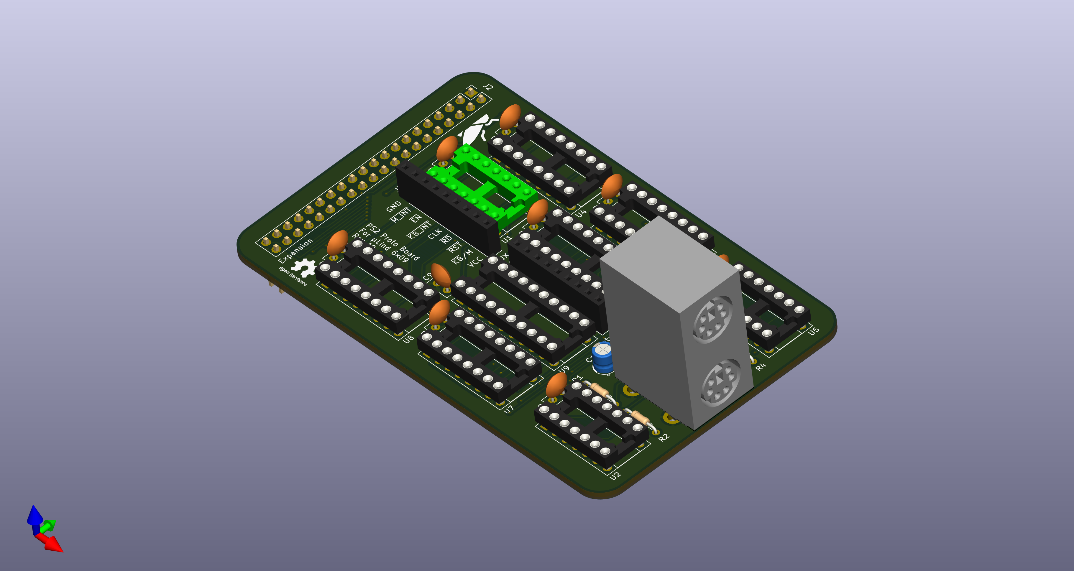
07/31/2025 at 11:04 • 0 commentsSo, I finally got around to test the PS2 interface prototype. I made a simple test program that only checks for the interrupt and then prints the key pressed value and connected the board up to a Arduino Mega and turned on the power. I gave me some spurious interrupts but I was not surprised, after all, it is a prototype hooked up with test wires. So I decided to connect a keyboard.
That is when the smell and pop came... Nooo....
I unplugged everything, but the Arduino was beyond saving.So back to the schematics and looking at footprints. And low and behold, the footprint for the PS2 connector was mirrored. Which means that when I plugged in the keyboard I actually short circuited VCC and GND. And that is not something an Arduino likes.
This is why we make the small prototype boards to test things. To build a new µLind prototype board would have been more expensive than an Arduino.
-
Okey, lets dig in and find the fault!
07/05/2025 at 14:22 • 0 commentsSo yesterday me and my son sat down and pulled out the logic analyzer to finally find the fault. First we used the oscilloscope to verify the power delivery, and it was rock solid. Then we hooked up the major part of the bus (on the peripheral side of the bus transceivers) and started logging...
Well what do you know, when we started to verify the code with what we measured we found 2 things that will destroy any chances of stable execution:
- We found that when we loaded the stack pointer we used the wrong addressing mode, in the code we had "lds $E000" while it should be "lds #$E000". DOH! That meant we were loading the stack with an un-initialized value found at $E000 instead of loading it with actual E000.
- We also found small artifacts, only 5-15ns long, that in certain conditions made the processor more or less halt or reset. These spikes only appeared during write instructions, which lead me to believe that it could be a reflection or a spike from changing direction on the bus transceivers.
So this artifact problem rushes the issue of adding pullups on the bus, which I already had planned for stage 3, but I need to add those pesky pullups on the BA, BS and R/W signals as well since I could see the blips there to.
Hopefully this will make the bus a bit more stable and well behaved.
TL;DR The Stage 3 is soon being ordered! -
Ignoring the problems...
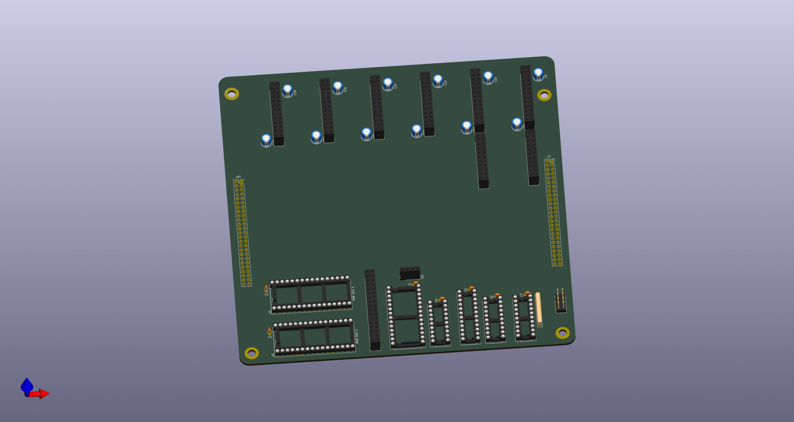
05/15/2025 at 07:25 • 0 commentsWhile we are stuck in the fault tracing I decided to start working on an expansion backplane. We wanted a possibility to add expansion cards to the µLind system and we settled on following requirements for the backplane:
- 6 expansion cards.
- 2 of the ports should have a complete address bus to it (for use with DMA functions for example.
- 2 sockets for 512kB ram, for up to 1MB of expanded ram.
- Possibility to chain one more backplane to the first for additionally 6 ports and 1MB ram.
- Slot for I2C expansion, giving the backplane a way of auto configure the different added expansion cards.
- Possibility to add RTC clock.
- Own address handler and IRQ handler.
So below is a picture of the first draft of the Expansion Backplane:
![]()
-
Why can't everything just work!!!
05/06/2025 at 07:52 • 0 commentsWe have been working a lot on the Stage2 board with different SW concepts and Ideas, and now it was time for testing advanced IRQ handling. Like setting up a timer on the serial chip and use that to blink the LED.
But when we flashed the ROM and started the application (the board has been standing unused on my desk for week now) nothing worked. So we scaled it back and only set the LED and just threw us in a loop after that.
Flashing ROM.
Starting µLind...
The LED turned on, but after 2s it turns off. We measured the 5v and it was good and clean... If the only thing we do is to write a 2 in a register and then we loop, and that does not work... I'm clueless!
So next step is to connect the logical analyzer and see what happens.... **Sigh**
-
Finally, Stage 2 is tested and working!!!
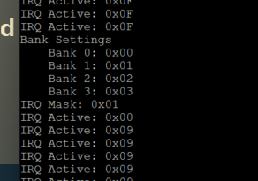
04/16/2025 at 20:08 • 0 commentsYesterday we finally got the IRQ-handler working on the stage 2 board!
![]()
That means that all features of stage 2 is tested and working properly. My son is now focusing on writing a SREC parser for our serial routines so we can simplifying testing of applications. No more flashing and swapping EEProms! And the final thing to test is the PS2 interface I built as an expansion for the Stage 1 board. At least I was smart to build the PS2 board so it would be possible to test stand alone, without any computer connected to it so I can test it without starting the Stage 1 board again! That one is relegated to the dusty shelf of history now!
![]()
-
All systems are go!
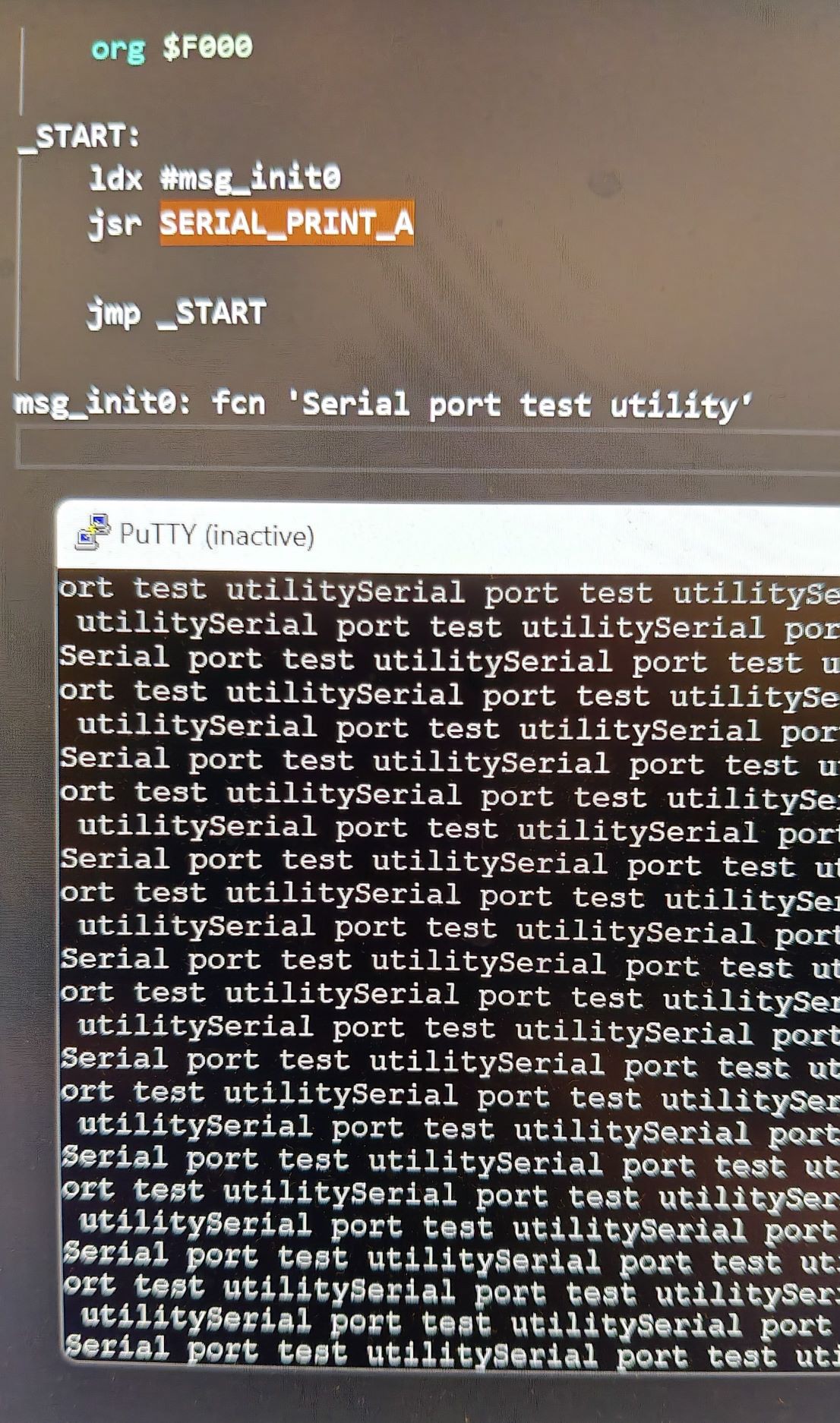
04/05/2025 at 15:07 • 0 commentsTwo days ago, we finally got all components working (sort of) on the stage 2! We sat down and made the serial communication work, there were just some minor tweaks to the code my son had written for the serial controller, and the tiny detail of actually start the serial tranciever after initializing (DOH!) and it worked perfect!
![]()
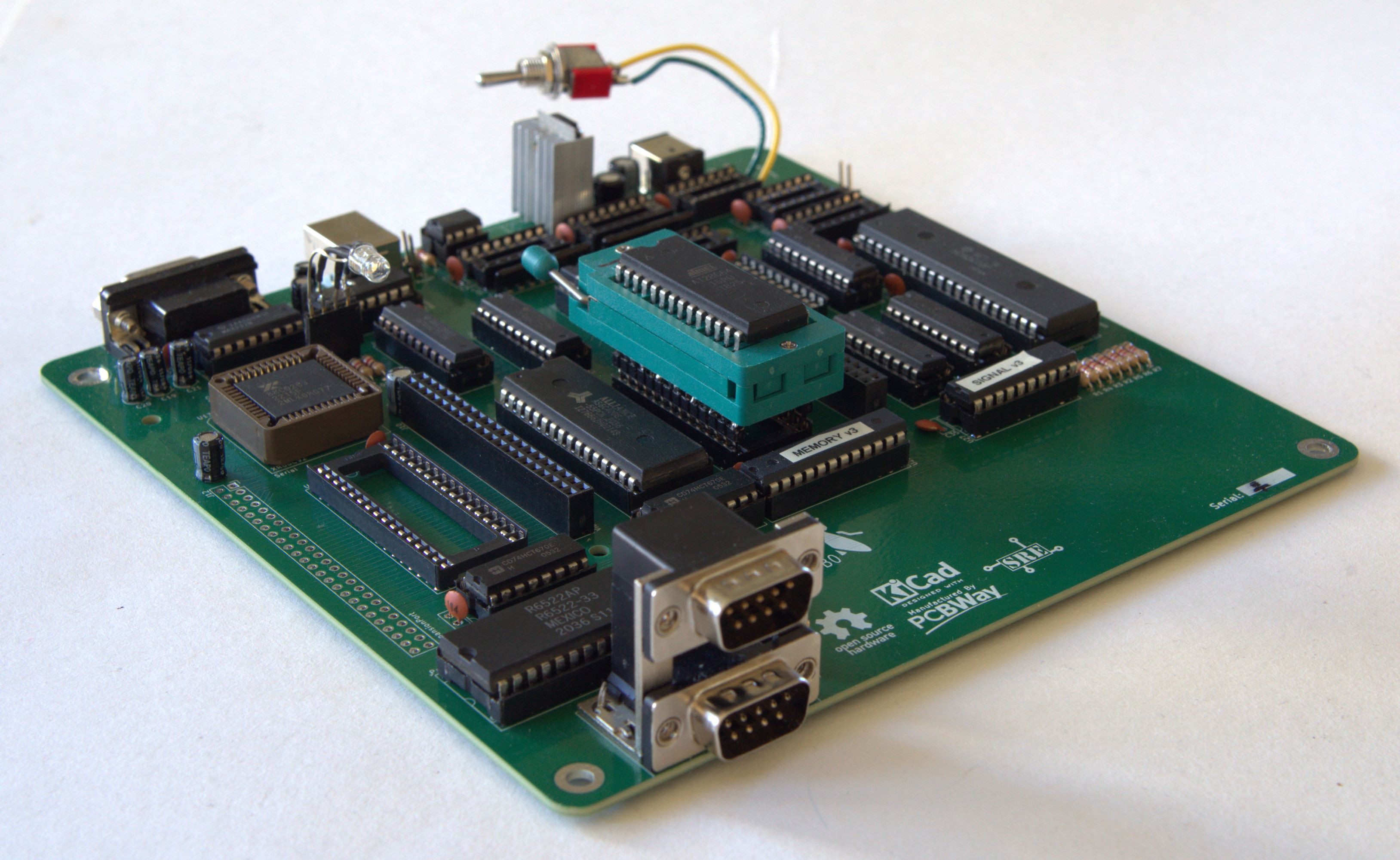
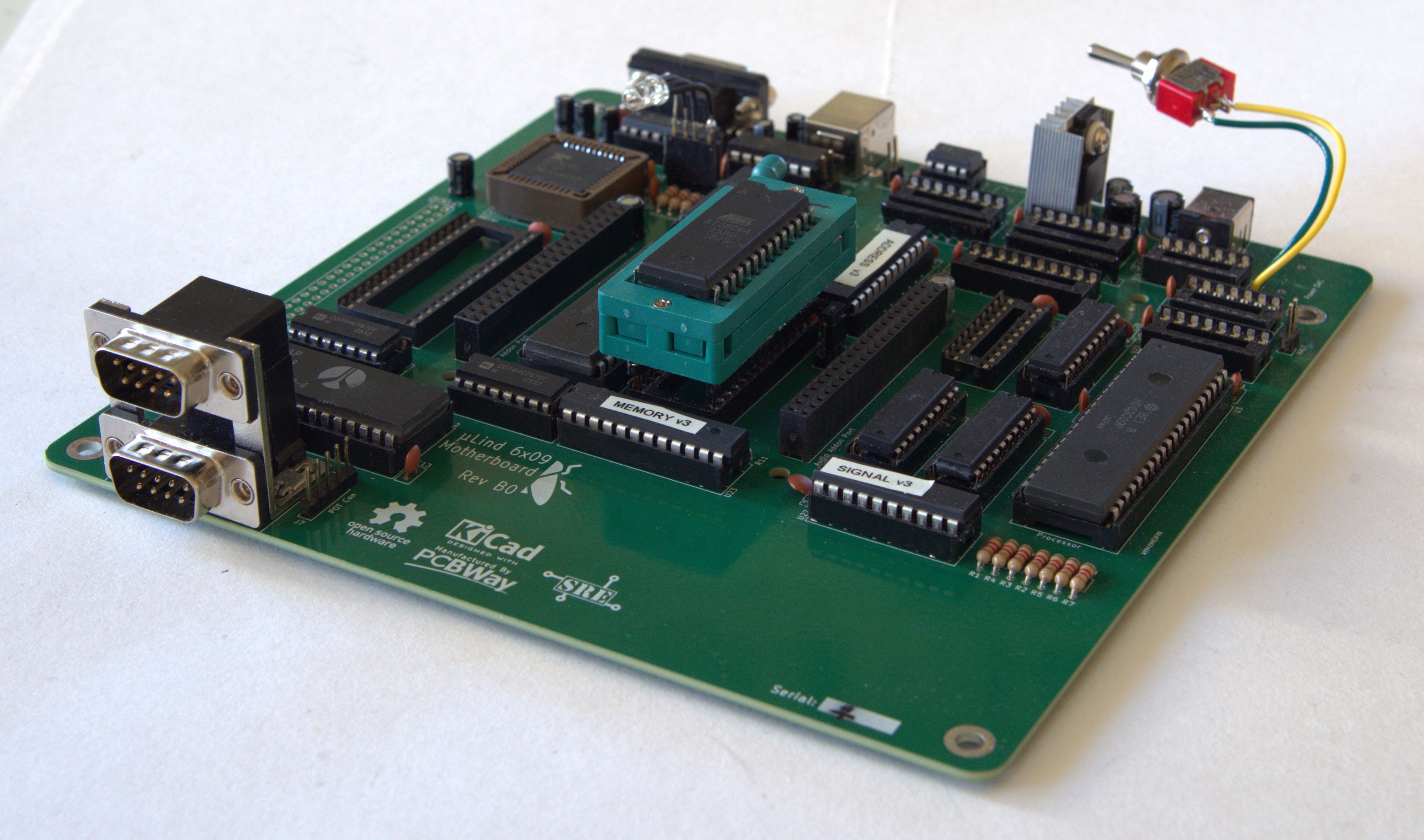
The parallel port (joystick ports) needed a missing pullup resistor to not have the inputs floating. Small miss but the stage 3 drawings are already updated. So after this, the computer deserverd a beauty shot:
![]()
![]()
So now the only thing that is left on stage 2 is the IRQ Handler, the 7 unpopulated circuits on the bord (apart from the extra RAM socket).
Thank you PCBWay for helping me making this dream come true!
![]()
-
Stage 2 is working!
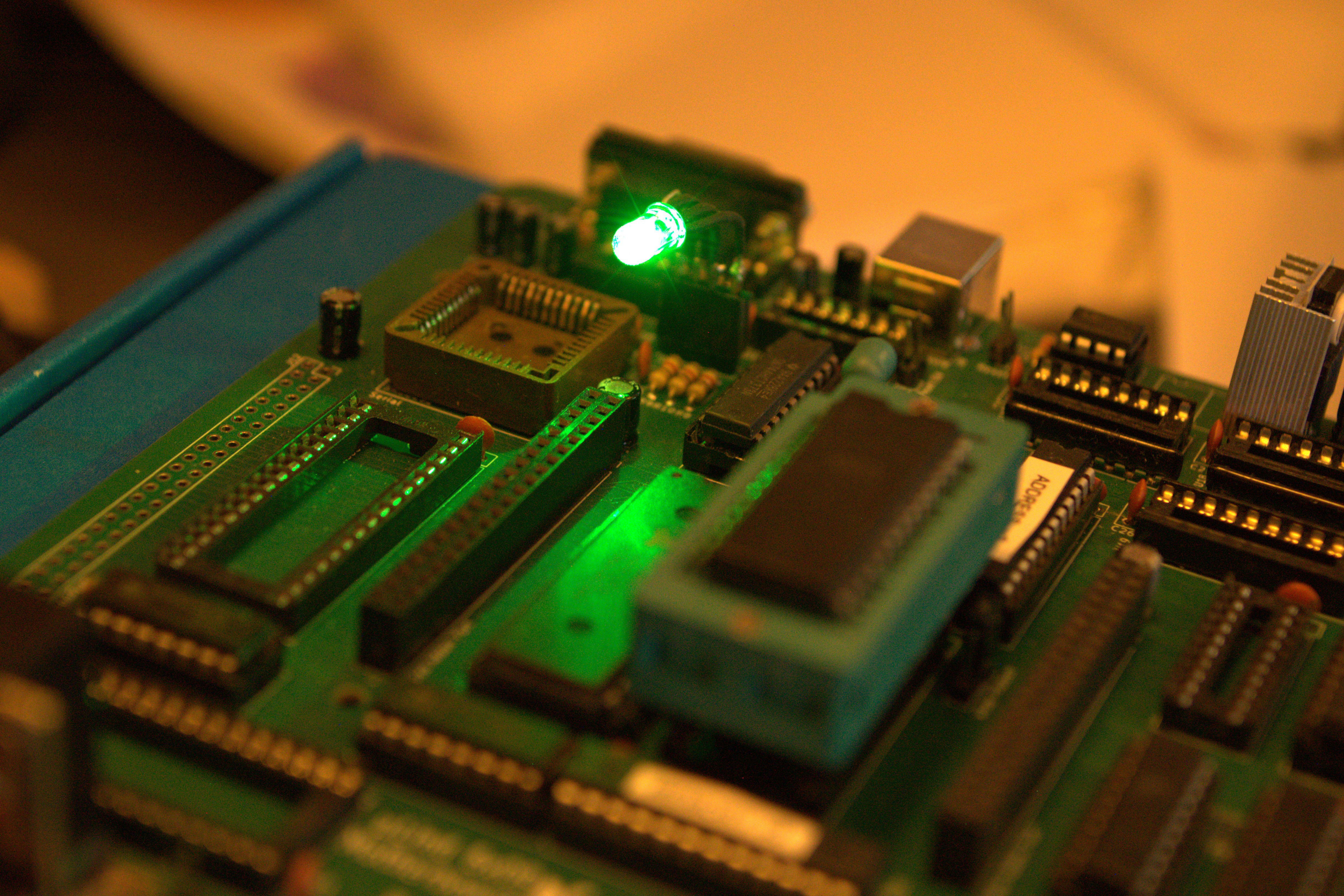
04/01/2025 at 18:59 • 0 commentsToday we finally got the stage 2 to work properly, we got a led blinking!
We started with a small code that should cycle thru the colors of the rgb led we got connected to a register.
![]()
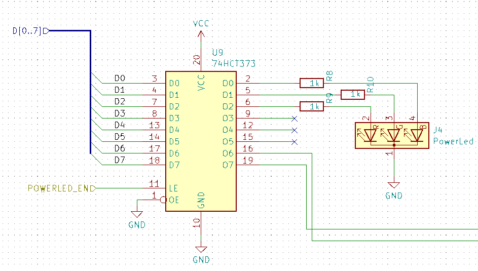
When we tried the code the led only blinked once and was dark after that. When we looked in to the schematics we found that we were generating a active low enable signal from our address-logic and the 373 chip needed active high logic.
Easy fix, we just change a line in the GAL code:
PIN 14		= !EXP_EN	; /* Enable Expansion Port     */
PIN 15   	= !VDC_EN	; /* Enable Video Port         */
PIN 16    	= !SNDR_EN	; /* Enable Sound Port Right   */
PIN 17    	= !SNDL_EN	; /* Enable Sound Port Left    */
PIN 18		= !CF_EN	; /* Enable Compact Flash      */
PIN 19    	= !PAR_EN	; /* Enable Parallel Port      */
PIN 20    	= !SER_EN	; /* Enable Serial Port        */
PIN 21    	= PWR_EN     	; /* Enable PowerLed Port      */   <--- HERE!
PIN 22    	= !IRQ_EN       ; /* Enable IRQ Handler        */
PIN 23   	= !MEM_EN       ; /* Enable MMU                */
After we fixed that we got it to light up, but not change color... Hmmm... After some looking at the code we realized that if the stack was not properly set up the jump instructions used in the delay would not work. Said and done, we updated the code and added initialization of the bank register for good measure :
    org $FE00

PWR_LED     EQU $F405
BANK_REG_0  EQU $F400
BANK_REG_1  EQU $F401
BANK_REG_2  EQU $F402
BANK_REG_3  EQU $F403

_START:
    clrb
LOOP:
    stb PWR_LED
    ldx #$03E8
    jsr DELAY_MS
    cmpb #$07
    beq _START
    incb
    bra LOOP

DELAY_MS:
    lda #$7C            ; 2 cycles
DELAY_MS_LOOP:
    nop                 ; 1 cycle
    nop                 ; 1 cycle
    nop                 ; 1 cycle
    deca                ; 1 cycles
    cmpa #$00           ; 4 cycles
    bne DELAY_MS_LOOP   ; 3 cycles
    nop                 ; 1 cycle
    nop                 ; 1 cycle
    nop                 ; 1 cycle
    nop                 ; 1 cycle
    nop                 ; 1 cycle
    nop                 ; 1 cycle
    leax ,-x            ; 5 cycles
    cmpx #$0000         ; 4 cycles
    bne DELAY_MS        ; 3 cycles
    rts                 ; 4 cycles

STACK EQU $1000

    org $FF00

HOOK_RESTART:
    ; Initialize the 6309 CPU in native mode
    ldmd #$01

    ; Initialize the bank registers
    clra
    sta BANK_REG_0
    sta BANK_REG_1
    sta BANK_REG_2
    sta BANK_REG_3

    ; Set up the stack
    lds #STACK

    lbra _START

HANG:
    bra HANG

    org $FFF0

vrestart: fdb HOOK_RESTART
With this fixes the power led started cycling as expected! IT WORKS!
![]()
This means that following works:
- Signal logic
- Address logic
- Memory logic
- Bank registers
- PWR_LED register with led
- Low RAM and ROM
Next up is to get the serial port working, my son is working on a SREC parser so we will be able to upload code to execute and run.
-
Finally, all logic chips are validated!
03/20/2025 at 18:59 • 0 commentsToday we finally sat down and tested the Signal-Logic chip, the chip responsible for creating the RW and WR signals and also some other signals like the MEM_RD/MEM_WR that is used for the banking system.
We have tried to validate this chip several times and did not get the correct functionality, on the contrary, we get the opposite functionality! Hmmm... When we expect a logical HIGH we got a LOW and vice versa. We even made a super simple 2 input and 2 output program to test but to no avail.
After several attempts of testing and reading we finally got it to work as assumed (don't ask how we fixed it, it was magic...). So now we have all 3 logic chip working as intended and tested. So next step will be testing the new bus transceivers to make sure we don't fry our processor. And when that is done, we can start test ROM & RAM.
Name     Test ;
PartNo   00 ;
Date     2025-03-29 ;
Revision 1 ;
Designer Engineer ;
Company  Sperly Retro Electronics ;
Assembly None ;
Location  ;
Device   G16V8A ;

/* *************** INPUT PINS *********************/
PIN 2    =  A                         ;
PIN 3    =  B                         ;

/* *************** OUTPUT PINS *********************/
PIN 18    = Y                      ;
PIN 19    = X                      ;

/* ********************* LOGIC *********************/
X = A & B;
Y = A # B;
This test program gave us inverted outputs and I did not figure out why.
-
I'm still here...
03/04/2025 at 07:21 • 0 commentsI haven't dropped the project, I've just been struggling with both GAL- problems and real life time issues. But my son has started to design and develop BIOS routines for the new stage 2 board.
The issues with the GAL is either depending on my lack of programming knowledge regarding Goals or as I thought about this morning, a dodgy chip. Need to get a new one and try that. I have started building a test bench for Goals using an Arduino Mega, to be able to automate the testing of the address and logic GALs.
I hope I can solve this soon, both me and my son are anxious to start SW development on the stage 2 board.