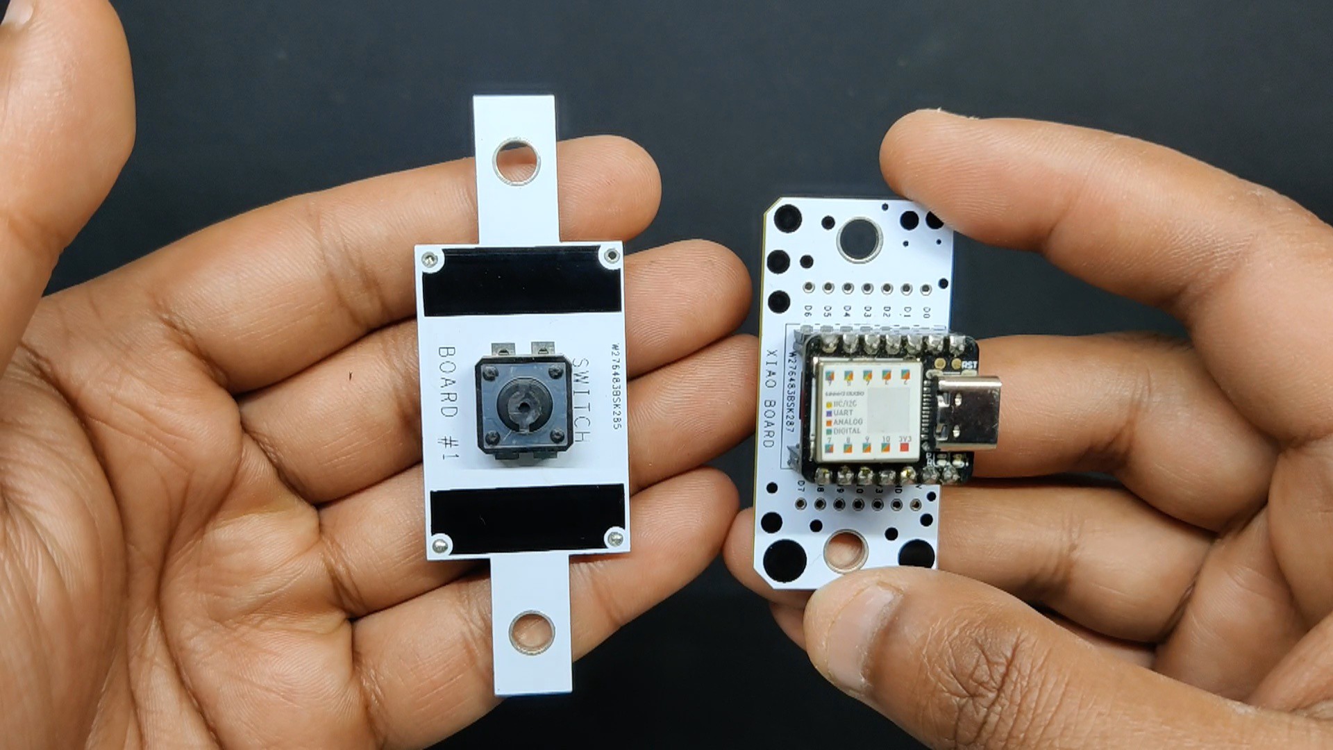
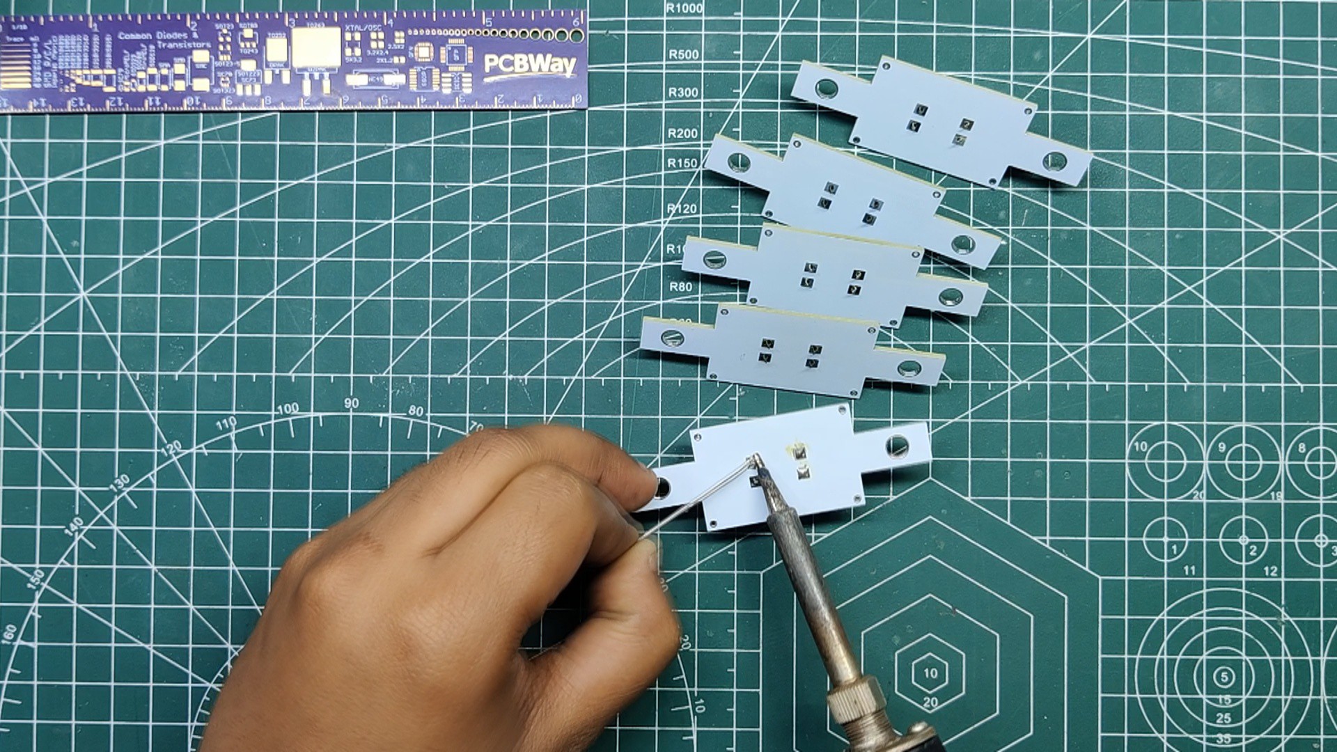
The PCB assembly process was basic. We began by assembling the switch PCB, which simply required a push button, which we positioned and soldered from the board's bottom side.
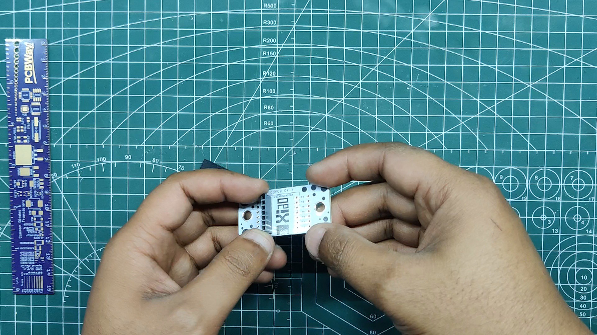
After that, we begin the XIAO Breakout board construction procedure by positioning both CON7 female header pins in their proper locations and soldering their pads from the PCB's bottom side.
At last, we added the XIAO M0 in its place using the header pins.
2
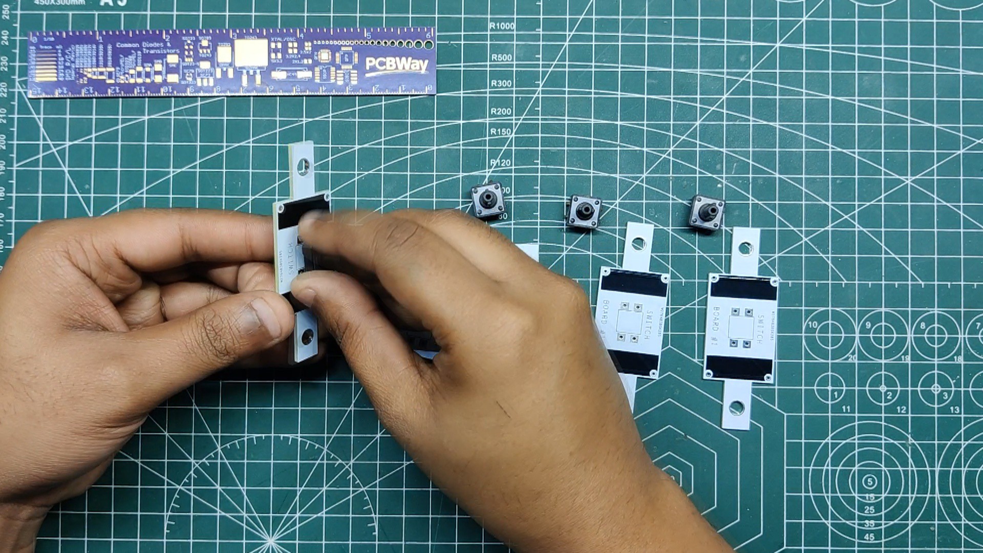
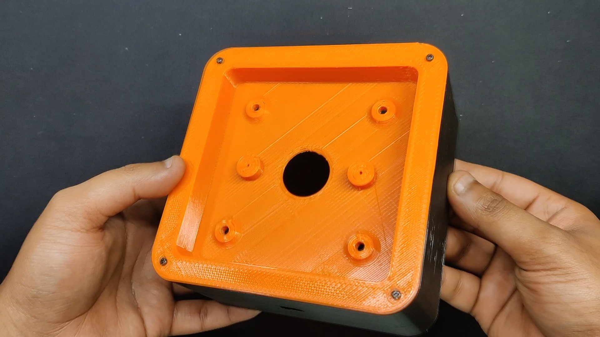
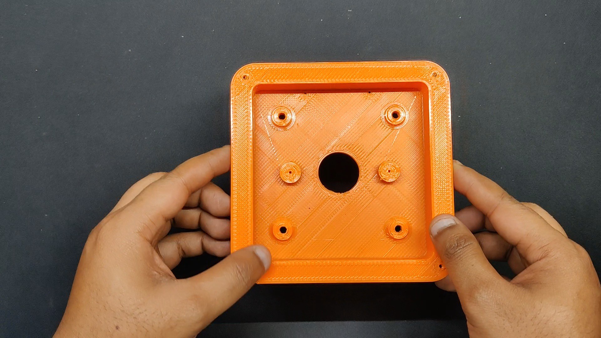
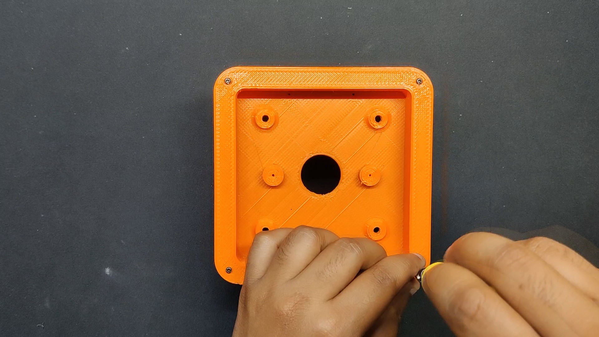
Frame Assembly process
In order to begin the body construction, we place the Switch Circuit holder part on top of the lower frame using M2 screws.
3
Button Actuator Assembly
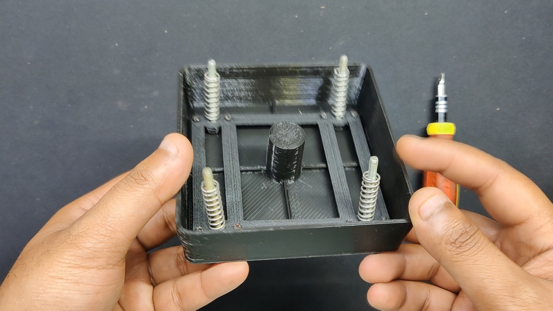
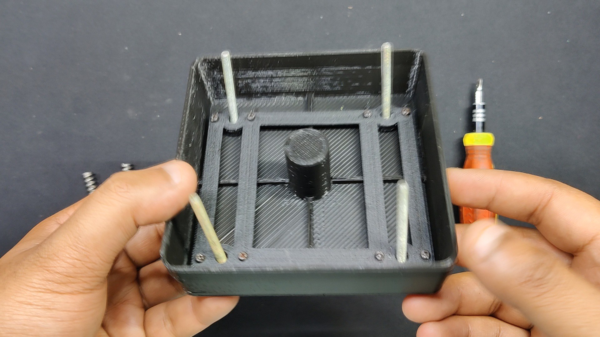
The button actuator assembly, which is made up of the keycap and spring mechanism, is then prepared.
This procedure begins with the installation of four M3 bolts in the spring mechanism part's mounting holes. Next, the spring mechanism part is inserted into the keycap, and the two are joined using M2 screws.
Next, we insert a spring into each M3 bolt. The spring is taken from an old Anet A8 3D printer's bed assembly, and the keycap assembly is essentially made using the same mechanism as the 3D printer bed
4
Frame and Button Actuator Assembly
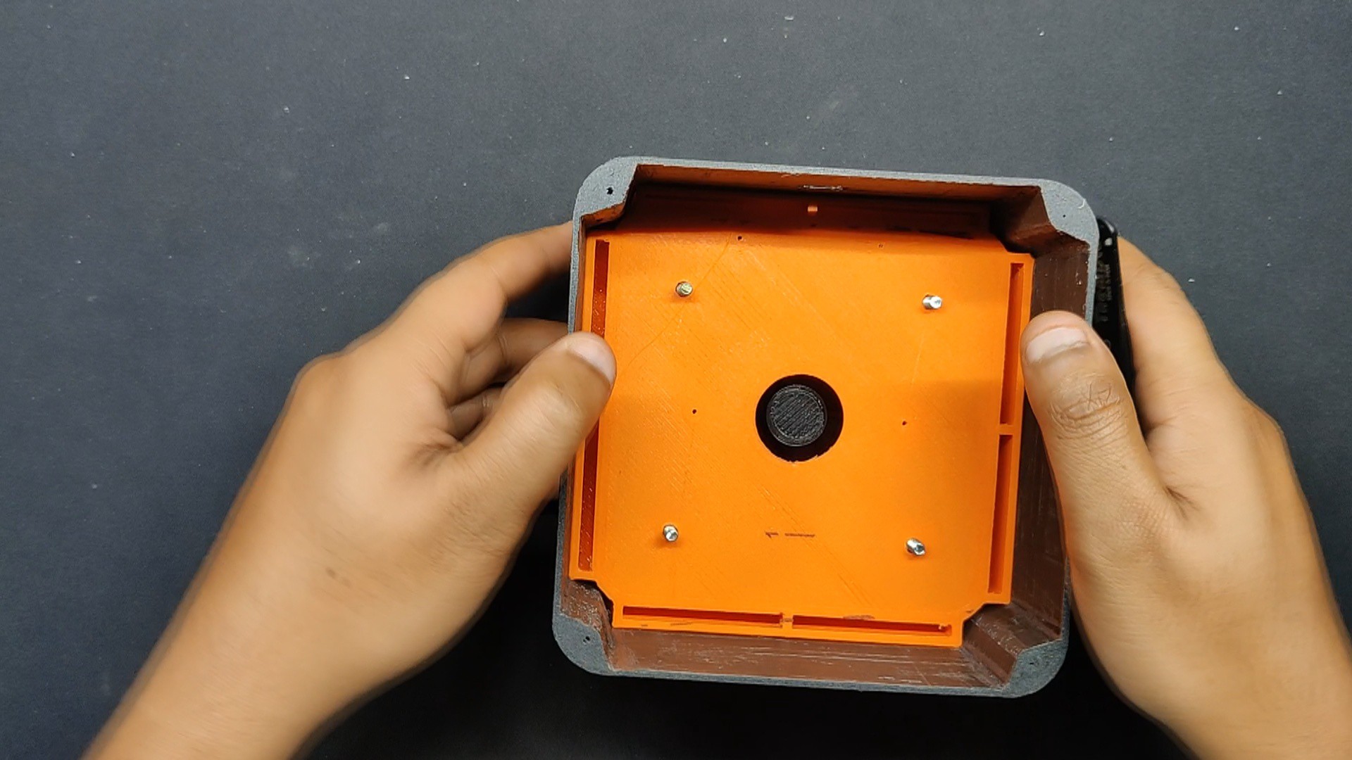
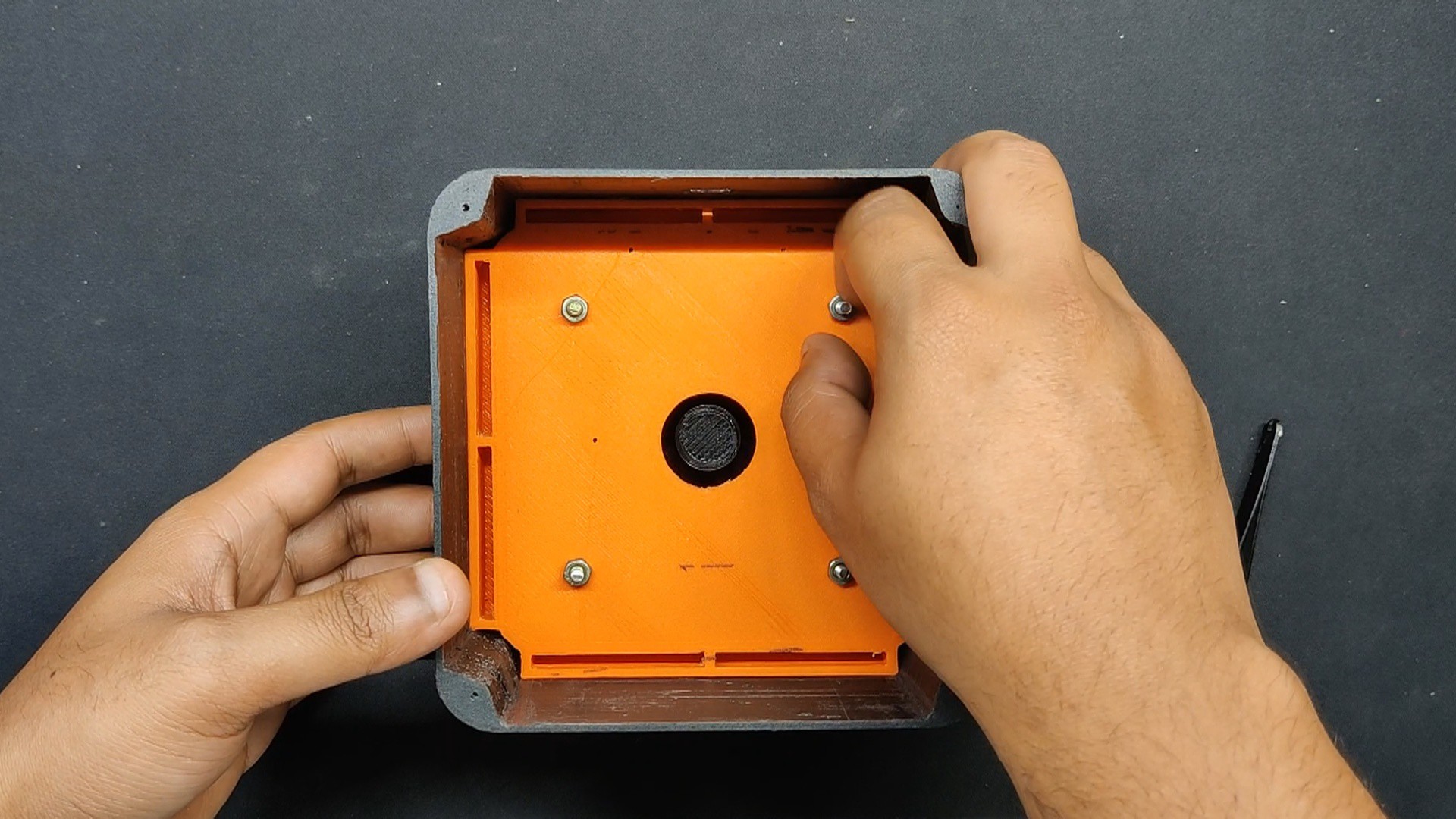
By positioning the Frame Assembly above the keycap and allowing the bolt to pass through its four mounting holes, we are now able to connect the Frame Assembly with the button actuator.
Then, in order to connect the button assembly and frame assembly, we attached four M3 nuts to each M3 bolt.
We added four more M3 nuts to ensure that everything was stationary and tight, and they tightened against one another to prevent them from coming free.
5
XIAO Breakout Board and Button PCB Assembly
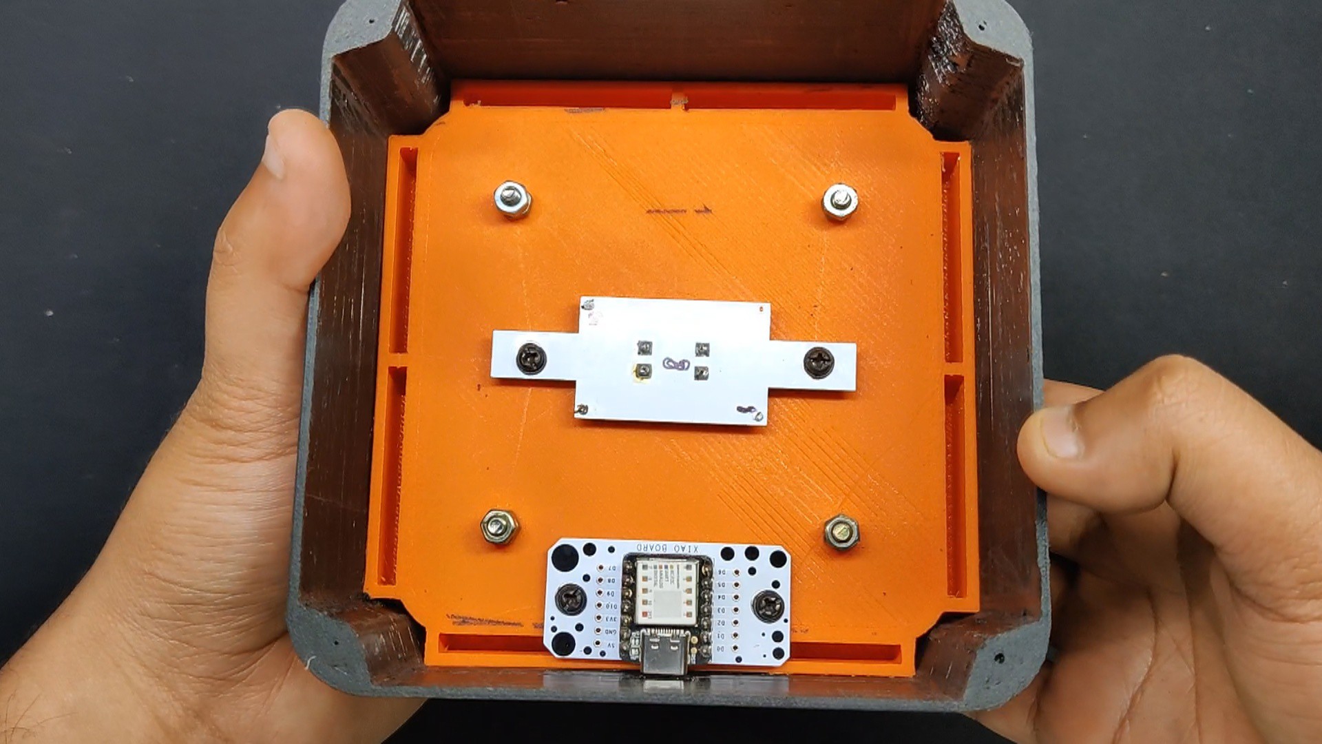
Now, the XIAO breakout board is positioned and fastened within the frame assembly with two M2.5 screws.
The Switch PCB is then positioned in the center of the Frame assembly, and it is secured in place with two M2.5 screws.
Now, both circuits are in their proper positions.
6
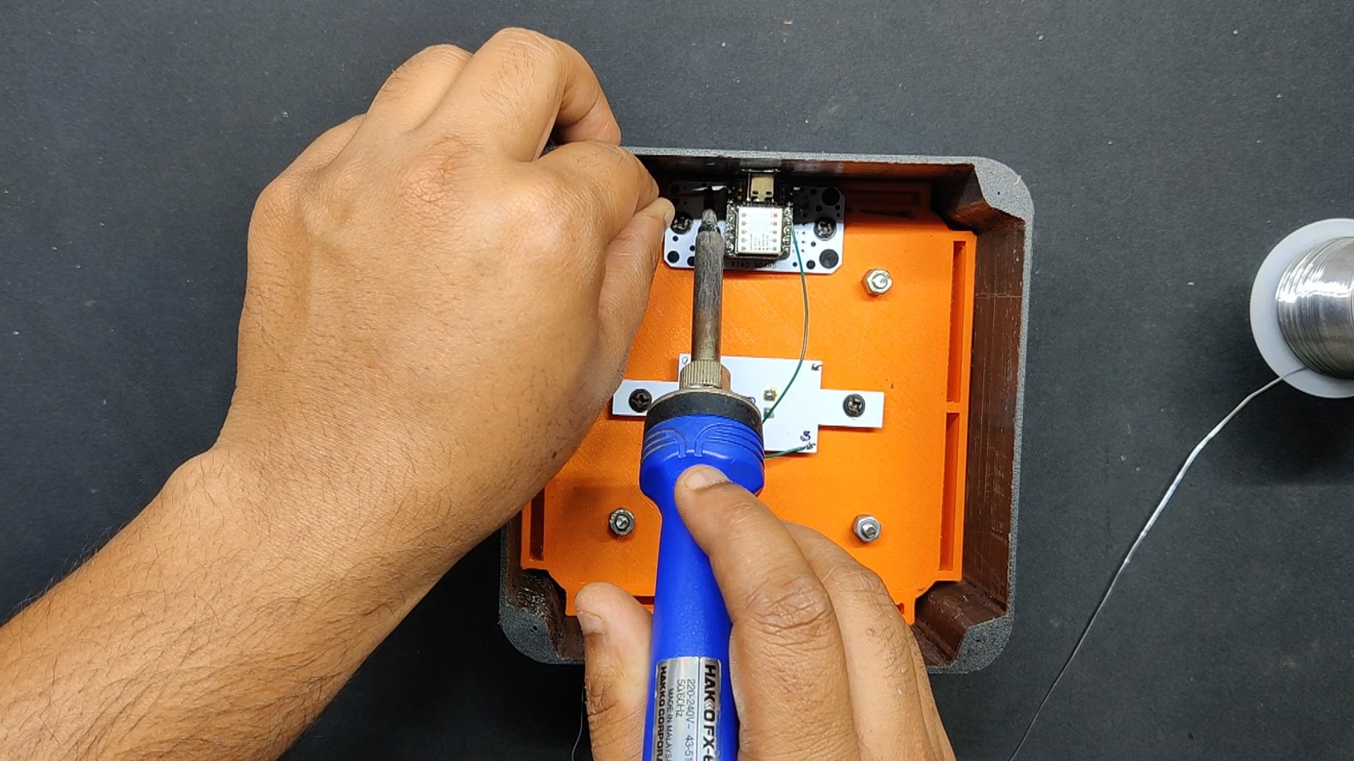
Wiring
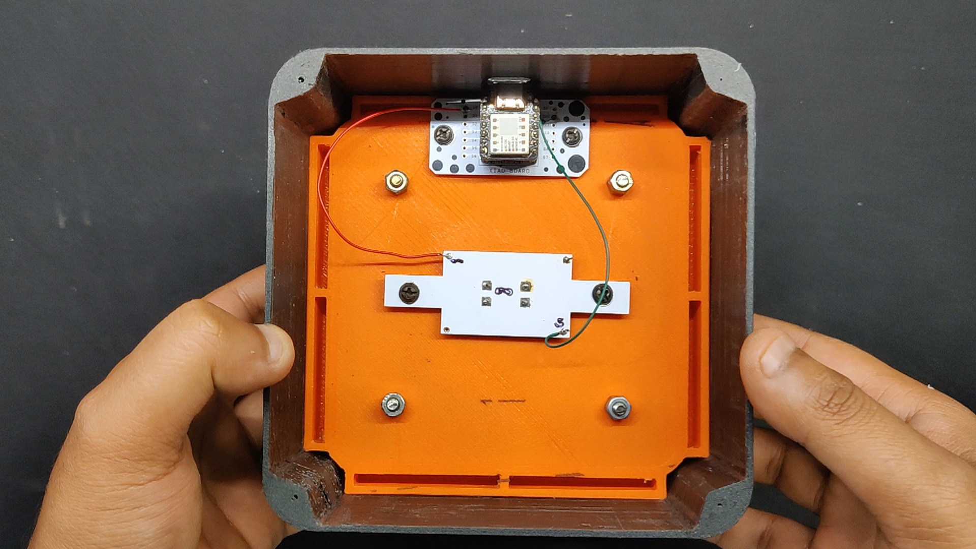
In order to complete this project, we used a soldering iron to connect a wire between the D0 Pin of the XIAO and one of the switch's terminals.
We then connected a wire between the switch's other terminal and the XIAO's GND.
In essence, this configuration is a switch connected to D0 of XIAO and GND; a keypress causes D0 to be pulled down, which is recorded as a keypress.
7
Final Assembly
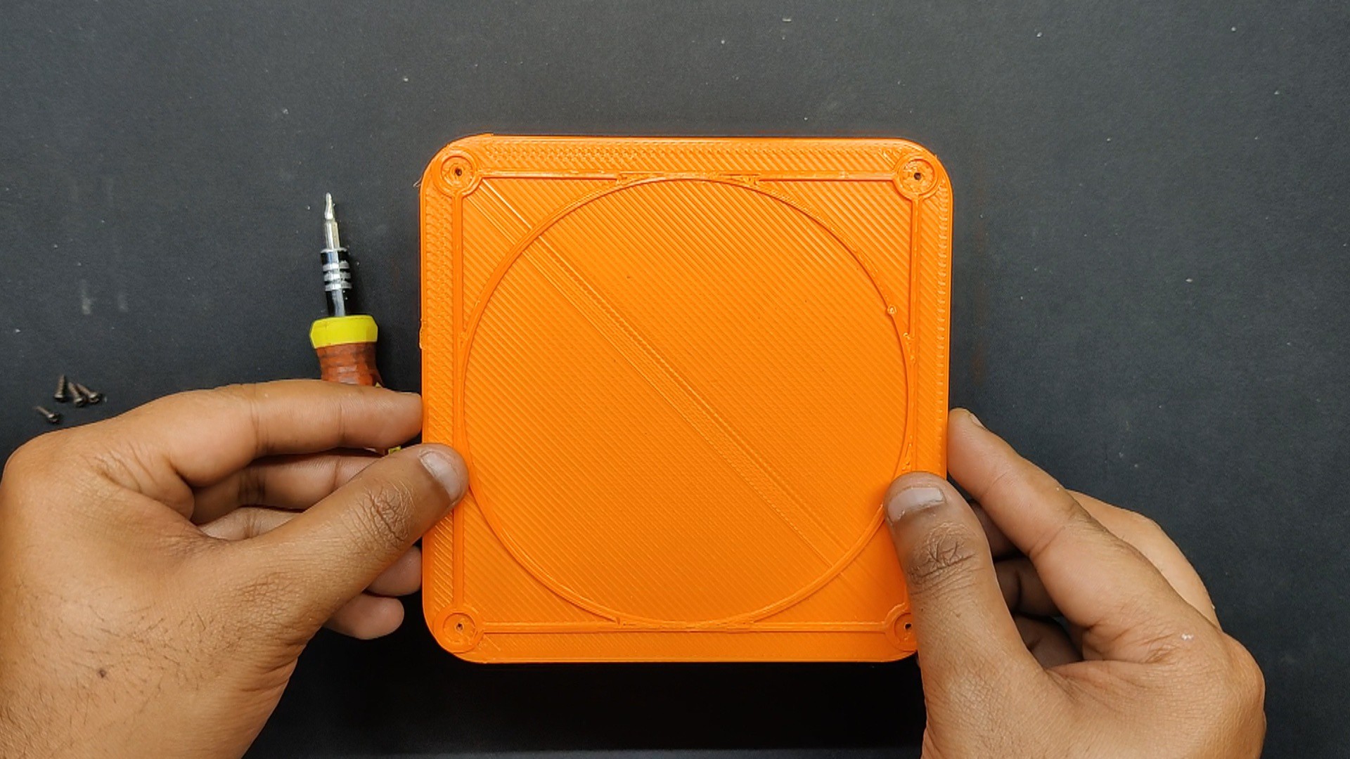
We next installed the lid on the frame assembly's bottom side and fastened it there with four m2 screws.
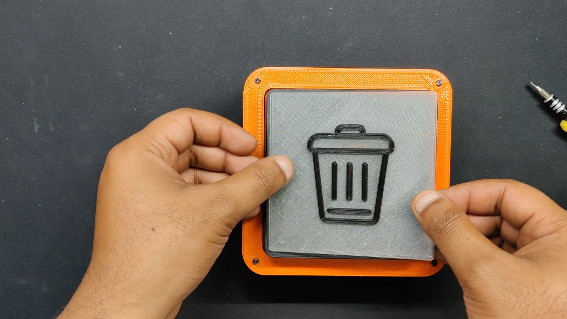
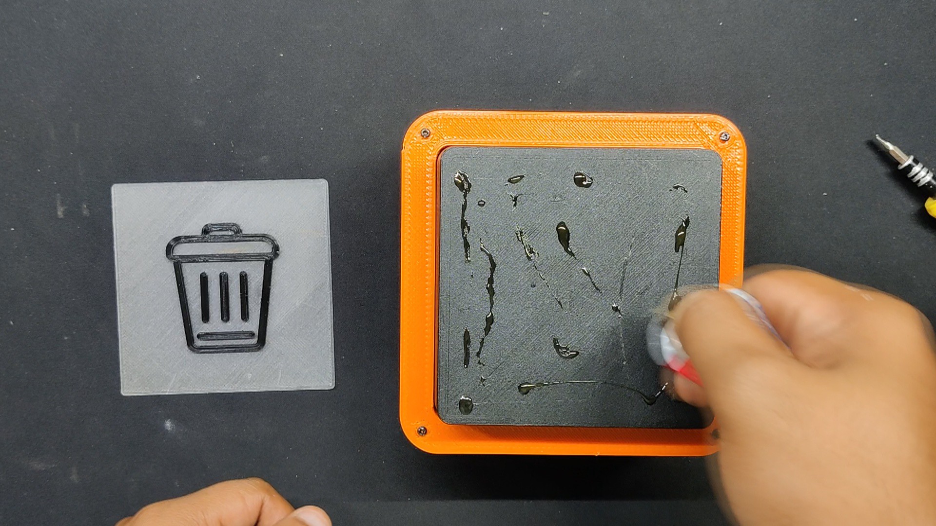
Finally, we take the dual-colored Delete Logo section and position it on top of the keycap.
The delete logo is placed on the keycap after superglue has been applied on the top of it to secure it in place.
8
CODE
Here's the main code used in this build.
#include"Keyboard.h"constint buttonPin = 0; // GPIO pin where the button is connectedint buttonState = 0; // Current state of the buttonvoidsetup(){
pinMode(buttonPin, INPUT_PULLUP); // Initialize button pin as input with internal pull-up resistor
Keyboard.begin();
}
voidloop(){
buttonState = digitalRead(buttonPin);
if (buttonState == LOW) { // If the button is pressed
Keyboard.press(KEY_DELETE); // Send Delete key press
delay(100); // Short delay to debounce the button
Keyboard.release(KEY_DELETE); // Release Delete key
delay(200); // Additional delay to prevent multiple triggers
}
}
This code sets up a button on GPIO 0 to send a Delete key press when the button is pressed. The delays help debounce the button to avoid multiple signals being sent for a single press.
9
RESULT
We try to delete some undesired images from our computer by plugging in the Delete Button. Because of the spring, the configuration is perfect, and there is a tiny resistance to the keypress when using this device.
It can delete anything, including the files, images, and any selected text. It can be used as a delete macropad in CAD applications or other editing programs.
Overall, this project was finished and required no further revision.
 Arnov Sharma
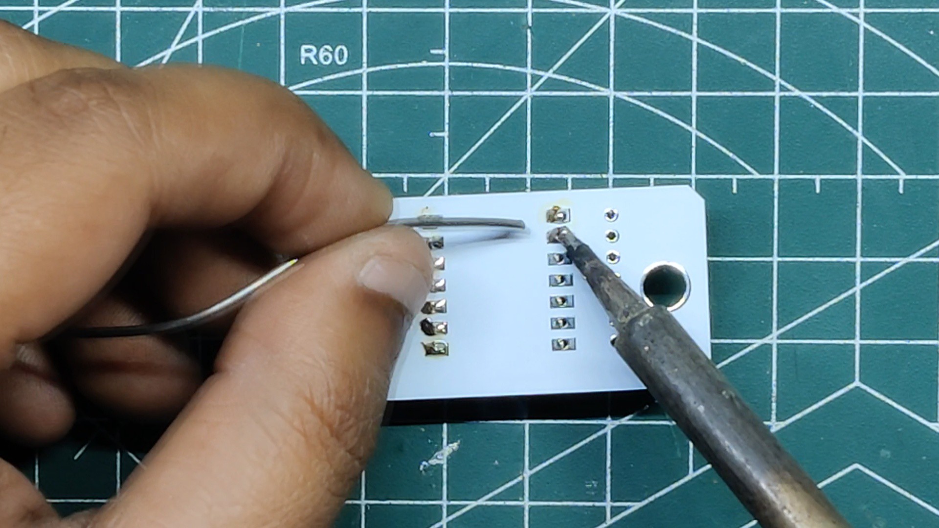
Discussions
Become a Hackaday.io Member
Create an account to leave a comment. Already have an account? Log In.