-
Make that a double Absinthe and a Hemlock chaser
10/17/2017 at 05:35 • 0 commentsMassive problems with that as a concept.
Well the code works in theory, and testing the individual units together works, but I cannot get the ESP to sync with the Atmels properly. I think it may be to do with the mismatch in processor speeds, but I cannot get all three and the PC to sync up and send meaningful data to each other.
![]()
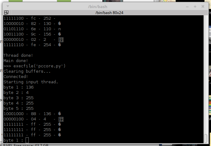
The pccore python code is fairly simple, all it does is accept and insert bytes from the terminal in a thread on its own, and passes packets not for itself. It deletes any for itself, and displays what is on the network. The PC has a USART with its RX and TX inserted into the chain after the ESP to make a square with a device on each corner - eventually this would be a RasPi or something - and the ESP would inject packets from the WiFi, which the Pi would be able to service.
As you can see, sending a packet from a processor to itself works with another processor connected to it;
That packet says from processor 4 (PC) to processor 4, sensor data, 255 255 255, and always works with at most one processor plugged into the chain. The processor reads the header and bounces it, and the PC deletes it when it comes back so it doesnt loop. In theory, a chain of hundreds of processors is possible, however, add another in the chain and it usually works, add a third, particularly the ESP and it fails with garbage returned, and I cannot figure out why. It isnt my code, I cant tell if it's Arduino's or a basic hardware issue so I'm going to have to abandon the idea.
Losing my processor solution this late in the game is a killer, I dont know what to do now other than directly hook 10 servos to one Atmel and drive them over a single RX TX serial link. I know from experience this will be rough and jerky, and probably fall over, but I have to try right?
-
Ordering a double Latte in C++
10/12/2017 at 08:34 • 0 commentsOK so now I'm wandering around muttering code. As you may be aware I design out of my head and document the results after building, and code is no exception. Somehow, I've managed to build a multiprocessor semaphore that ties two identical pieces of code to a third very similar one, all three run transparently and interact with each other and its puddled my brain lol. I dont even drink coffee either. ;-)
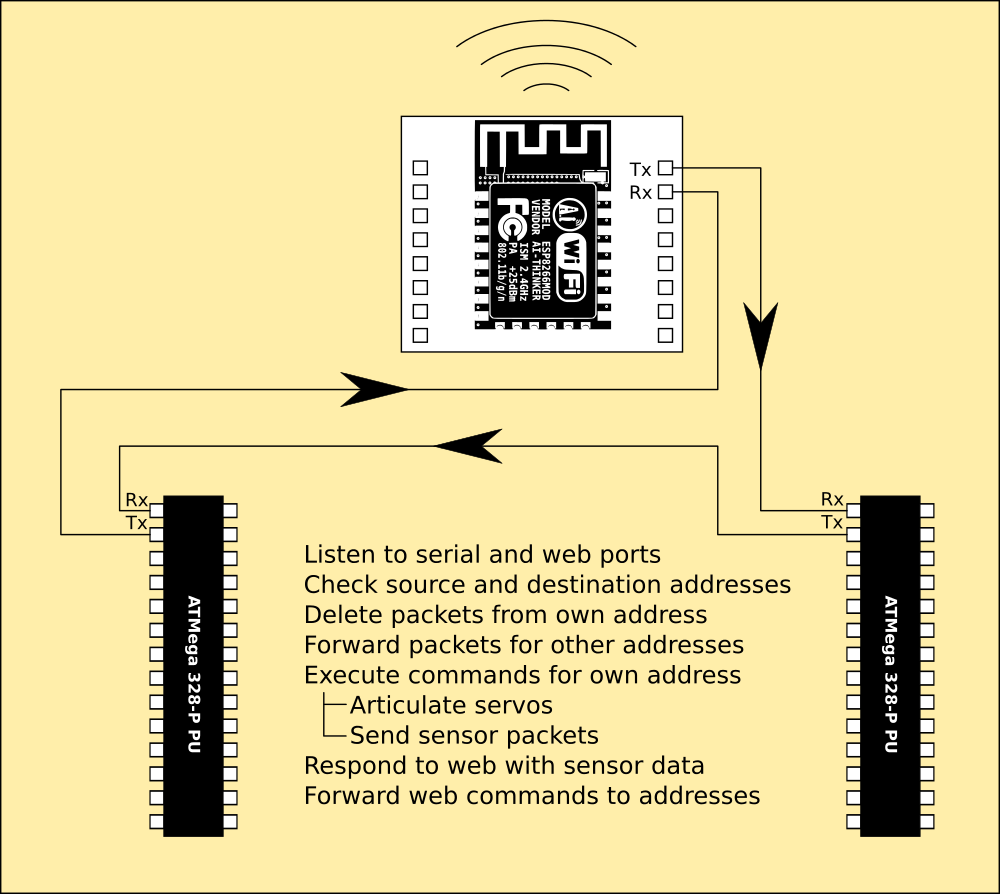
The processor board has two Atmega 328 and one ESP8266, and they are networked together by joining the TX pin on each to the RX pin on the next to make a triangle with the processors on each corner.
![]()
Obviously they will need to pass data internally from RX to TX, and this would loop forever without some kind of semaphore so I have defined a protocol.
The data is sent using a 5-byte packet.
Byte 1 contains the header - two 4-bit numbers that specify where the packet came from and where its going to. They are bit-wise so that a processor may address both the other at once by combining their ID bits.
Byte 2 contains a command code and parameters - 3 bits tell the system that the packet is a servo instruction or a request for sensor data, or sensor data itself. 4 more bits optionally give the servo number if it is a servo instruction, and bit 8 is always spare for now.
Bytes 3 - 5 contain data in an arbitrary format. For a servo instruction byte 1 gives the angle and byte 2 gives the number of steps to take to move to it from the current angle, byte 3 is blank. For a data request all three are blank, and for a sensor data packet the three bytes contain the three angles from the sensors.
The Atmega 328 code
Each processor reads its RX and looks at the header. If the source ID is the same as its own, the packet has made a circuit and is deleted. If it is for another processor it is passed to TX, after checking to see if it is also for this processor. if it is, the ID is removed from the header and the packet passed to TX. Any data for the processor is processed and sent to servos, or responded to with a sensor packet.
//#include "EEPROM.h"
#include <Servo.h>
const int host=4;                                 // this processor
const int servos=5;
// servo definition structure:
// articulation
//      |____ servo (servo object)
//      |          |____ attach()
//      |          |____ write()
//      |____ pin (physical pin number)
//      |____ min (minimum range of movement 0-255)
//      |____ max (maximum range of movement 0-255)
//      |____ home (home position defaults to 128; 90 degrees)
//      |____ position (positional information)
//                 |____ next (endpoint of movement)
//                 |____ pos (current position as float)
//                 |____ last (beginpoint of movement)
//                 |____ steps (resolution of movement)
//                 |____ step (pointer into movement range)
//
// packet configuration:
// byte 1: header - 2 nybbles containing source id and destination id
// byte 2: control - bits 1-3 packet type, bits 4-7 command parameters, bit 8 spare
// byte 3: data 1 - arbitrarily assigned
// byte 4: data 2 - arbitrarily assigned
// byte 5: data 3 - arbitrarily assigned
// eg
//        byte 1: 33/1000,0100 packet from processor 1 to processor 2 (esp to atmel a)
//        byte 2: 9/100,1000,0 position command for servo 1
//        byte 3: data 1 - angle (0-255 at the moment, will be percentage of range)
//        byte 4: data 2 - steps (divisions in angular displacement)
//        byte 5: data 3 - spare
// eg
//        byte 1: 33/1000,0100 packet from processor 1 to processor 2 (esp to atmel a)
//        byte 2: 10/010,1000,0 request for sensor data
//        byte 3: data 1 - spare
//        byte 4: data 2 - spare
//        byte 5: data 3 - spare
// eg
//        byte 1: 20/0010,1000 packet from processor 3 to processor 1 (atmel b to esp)
//        byte 2: 12/001,0000,0 sensor data
//        byte 3: data 1 - sensor 1
//        byte 4: data 2 - sensor 2
//        byte 5: data 3 - sensor 3
struct servo_position {                           // servo status
  int next;
  float pos;
  int last;
  int steps;
  int step;
} ;
typedef struct servo_position servo_pos;          // atmel c++ curiosity, substructs need a hard reference
struct servo_definition {                         // servo information
  Servo servo;
  int pin;
  int min;
  int max;
  int home;
  servo_pos position;
} ;
typedef struct servo_definition servo_def;        // servo structure containing all relevant servo information
servo_def articulation[servos];                   // array of servo structures describing the limb attached to it
int mins[]={ 0,0,0,0,0,0,0,0,0,0,0,0 };           // defaults for the servo ranges and positions
int maxs[]={ 255,255,255,255,255,0,0,0,0,0,0,0 };
int homes[]={ 128,128,128,128,128,0,0,0,0,0,0,0 };
void setup() {
  Serial.begin(115200);
  while (!Serial) { ; }                           // wait for the port to be available
  for (int s=0; s<servos; s++) {                  // iterate servos
    articulation[s].servo.attach(s+2);            // configure pin as servo
    articulation[s].pin=s+2;                      // echo this in the structure
    articulation[s].home=homes[s];                // configure the structure from defaults
    articulation[s].min=mins[s];
    articulation[s].max=maxs[s];
    articulation[s].position.next=homes[s];
    articulation[s].position.pos=homes[s];
    articulation[s].position.last=homes[s];
    articulation[s].position.steps=0;
  }
}
void loop() {
  if (Serial.available() > 0) {                   // if there is a packet
    unsigned char ids=Serial.read();              // read 2 bytes in; host and destination ids
    unsigned char ctl=Serial.read();              // control byte
    unsigned char b1=Serial.read();               // data bytes
    unsigned char b2=Serial.read();               // data bytes
    unsigned char b3=Serial.read();               // data bytes

    int hostid=ids & 15;
    int destid=(ids & 240)/16;
    if (hostid & host != host and hostid>0) {     // byte 1; if packet source is the same as host ignore it
      if (destid & host == host) {                // if host is in packet destination
        if (ctl & 7 == 1) {                       // if its a servo command in bits 1 to 3
          int srv=(ctl & 120) / 8;                // byte 2; mask out servo number from byte bits 4 to 7
          int agl=(int)b1;                        // byte 3; acquire angle
          int st=(int)b2;                         // byte 4; acquire steps
          articulation[srv].position.last=articulation[srv].position.pos; // capture current position as last position
          articulation[srv].position.next=agl;    // write new angle and steps into destination position
          articulation[srv].position.steps=st;
          articulation[srv].position.step=st;
          destid=destid ^ host;                   // xor out this host from packet destination
        }

        if (ctl & 7 == 2) {                       // if its a sensor data request send a sensor packet
          Serial.write(host+32);                  // byte 1 : host id plus destination bit 1; ESP
          Serial.write(4);                        // byte 2 : set bit 3; its a sensor packet
          Serial.write((int)analogRead(A0)/4);    // bytes 3 - 5 : sensor data
          Serial.write((int)analogRead(A1)/4);
          Serial.write((int)analogRead(A2)/4);
        }

        if (destid>0) {                           // if there is another packet destination
          ids=hostid+(destid*16);                 // pack the new header
          Serial.write(ids);                      // send the packet to another processor
          Serial.write(ctl);
          Serial.write(b1);
          Serial.write(b2);
          Serial.write(b3);
        }
        if (ctl & 7 == 4) {                       // if its a sensor packet pass to another processor
          Serial.write(ids);
          Serial.write(ctl);
          Serial.write(b1);
          Serial.write(b2);
          Serial.write(b3);
        }

      }
    }

  }

  for (int s=0; s<servos; s++) {                  // iterate servo structure
    int st=articulation[s].position.last;         // beginning of the movement
    int nd=articulation[s].position.next;         // end of the movement
    int stp=articulation[s].position.steps;       // how many steps to take to traverse the movement
    int sn=articulation[s].position.step;         // current step
    if (sn>0) {                                   // if pos hasnt reached its end of travel
      float ps=(((float)nd-st)/(float)stp)*sn;    // calculate new pos from travel and step
      articulation[s].servo.write((int)ps);       // set the servo to pos
      sn--;                                       // step counter
      if (sn<0) { sn=0; }
      articulation[s].position.pos=ps;            // update the structure
    }

  }

}
The ESP8266 code
This is a bit simpler in one sense, because it doesnt have sensors or servos to deal with. Code for these is missing, and extra code to handle a WiFi bridge is inserted. This is an asynchronous bridge, so its complicated and relies on a callback.
The ESP is setup as a soft AP with its own hostname and password, and has a webserver which provides a basic page containing the sensor data when a browser connects to it or reloads. This is accomplished by the webcallback routine, which will service a link from a Python program on a computer, or a phone running a MIT Appinventor app both with webkit code to interact with the processors.
Both pieces of code are as yet untested, they compile and are complete but I still have work to do before I can attach servos to any of it.
#include <ESP8266WiFi.h> // wifi stack #include <WiFiClient.h> // connection manager #include <ESP8266WebServer.h> // web framework const int host=1; // this processor const char *netw="network"; // static access point; cardware is a server const char *pasw="password"; int lsensor[]= { 0,0,0 }; // current sensor values int rsensor[]= { 0,0,0 }; String tmp; ESP8266WebServer server(80); // start webserver threads void webcallback() { // this runs when a browser connects or reloads the page tmp=String("<h1>Connected!\nLeft leg : "); // make a page with the sensor status information on it for (int n=0; n<3; n++) { tmp=tmp+lsensor[n]+","; } // in a temporary string tmp=tmp+"\nRight leg : "; for (int n=0; n<3; n++) { tmp=tmp+rsensor[n]+","; } // (this will be replaced with a semaphore between web host and esp) tmp=tmp+"\nOK\n</h1>"; server.send(200,"text/html",tmp); // and send it to the browser } void setup() { delay(1000); // wait for wifi to finish Serial.begin(115200); // open serial port while (!Serial) { ; } // wait for the port to be available WiFi.softAP(netw,pasw); // make a new access point using the provided ssid and password server.on("/",webcallback); // connect the server to the sensor data via a web-page server.begin(); // and launch it } void loop() { if (Serial.available() > 0) { // if there is a packet unsigned char ids=Serial.read(); // read 5 bytes in; host and destination ids unsigned char ctl=Serial.read(); // control byte unsigned char b1=Serial.read(); // data byte unsigned char b2=Serial.read(); // data byte unsigned char b3=Serial.read(); // data byte int hostid=ids & 15; // mask out host and destination ids from id byte int destid=(ids & 240)/16; // nybble 2, shift left 4 bits if (hostid & host != host and hostid>0) { // byte 1; if packet source is the same as host ignore it if (destid & host == host) { // if host is in packet destination destid=destid ^ host; // xor out this host from packet destination if (destid>0) { // if there is another packet destination ids=hostid+(destid*16); // pack the new header Serial.write(ids); // send the packet to another processor Serial.write(ctl); Serial.write(b1); Serial.write(b2); Serial.write(b3); } if (ctl & 7 == 4) { // if its a sensor packet pass to another processor // wifi bridge to host for now, RPi will handle it via serial eventually if (hostid & host == 2) { lsensor[0]=(int)(b1); // store the sensor positions lsensor[1]=(int)(b2); lsensor[2]=(int)(b3); } if (hostid & host == 4) { rsensor[0]=(int)b1; rsensor[1]=(int)b2; rsensor[2]=(int)b3; } } } } } server.handleClient(); // poll the webserver for a connection } -
Tacking like a Galleon
10/12/2017 at 07:52 • 1 commentThis skips about a bit I'm afraid, I've got to the point where the hardware is just about complete and I'm tidying up the last major solutions before I get into heavy coding, although that has begun...
I'm also working with Ars on his ZeroPhone documentation, so between code, electronics and artwork the rigging is beginning to creak. ;-)
First up, power train.
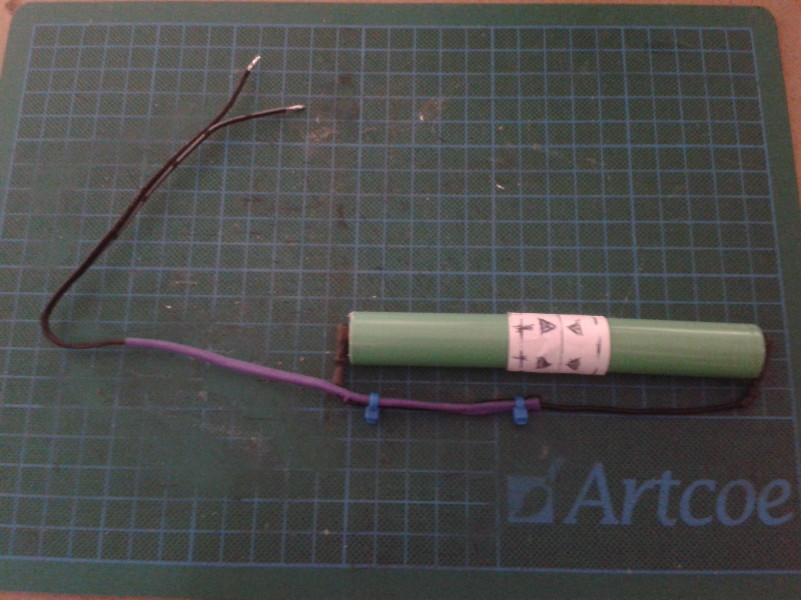
I've taken a large flat round magnet and stuck two cardboard discs onto the faces. Then its liberally covered with copper tape to give it a fully conductive skin. This comprises a prototype battery mount, made by rolling paper round the cells and magnet after applying a little glue. The battery is solid and makes a decent contact, but pulls apart easily.
![]()
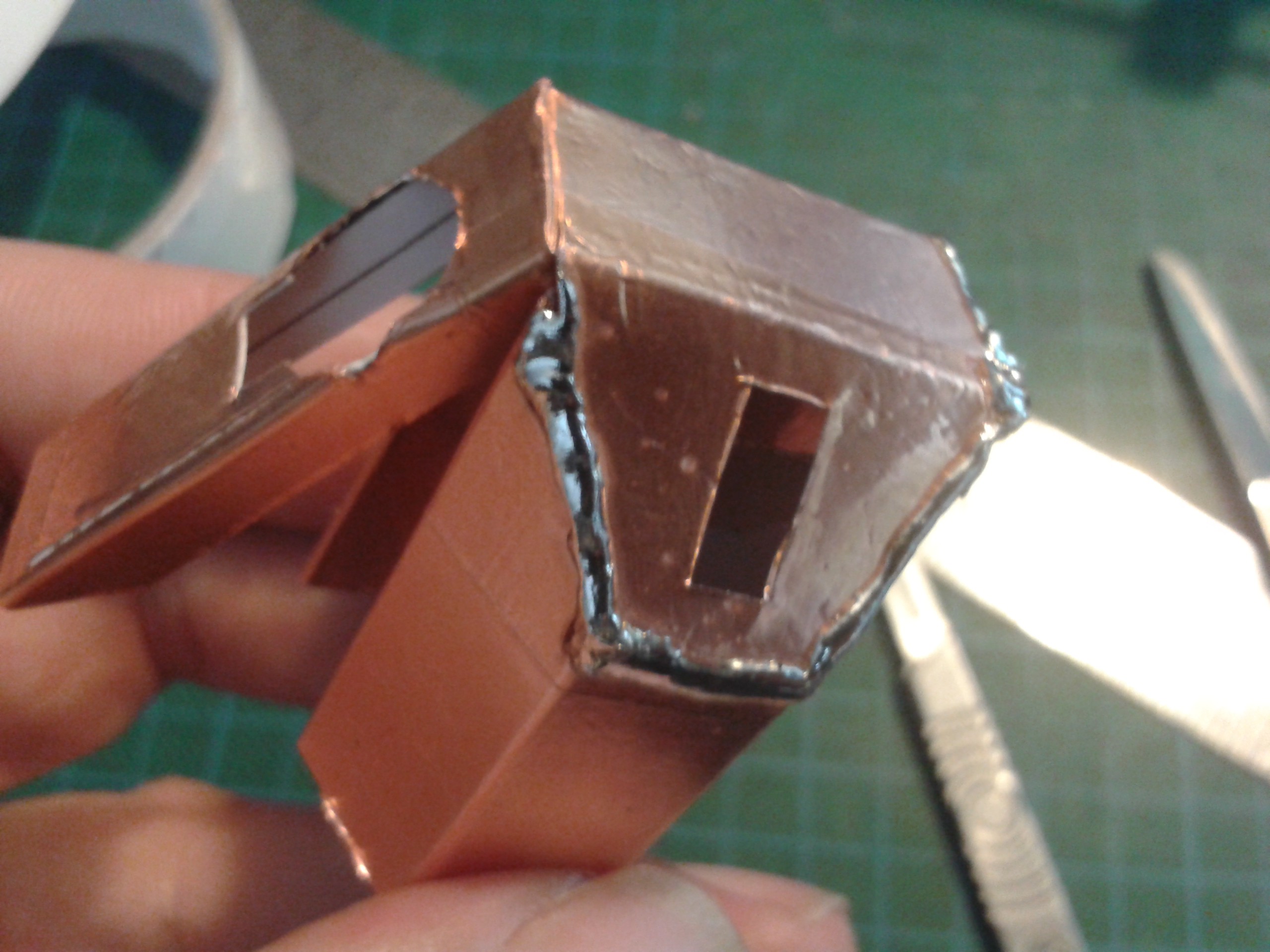
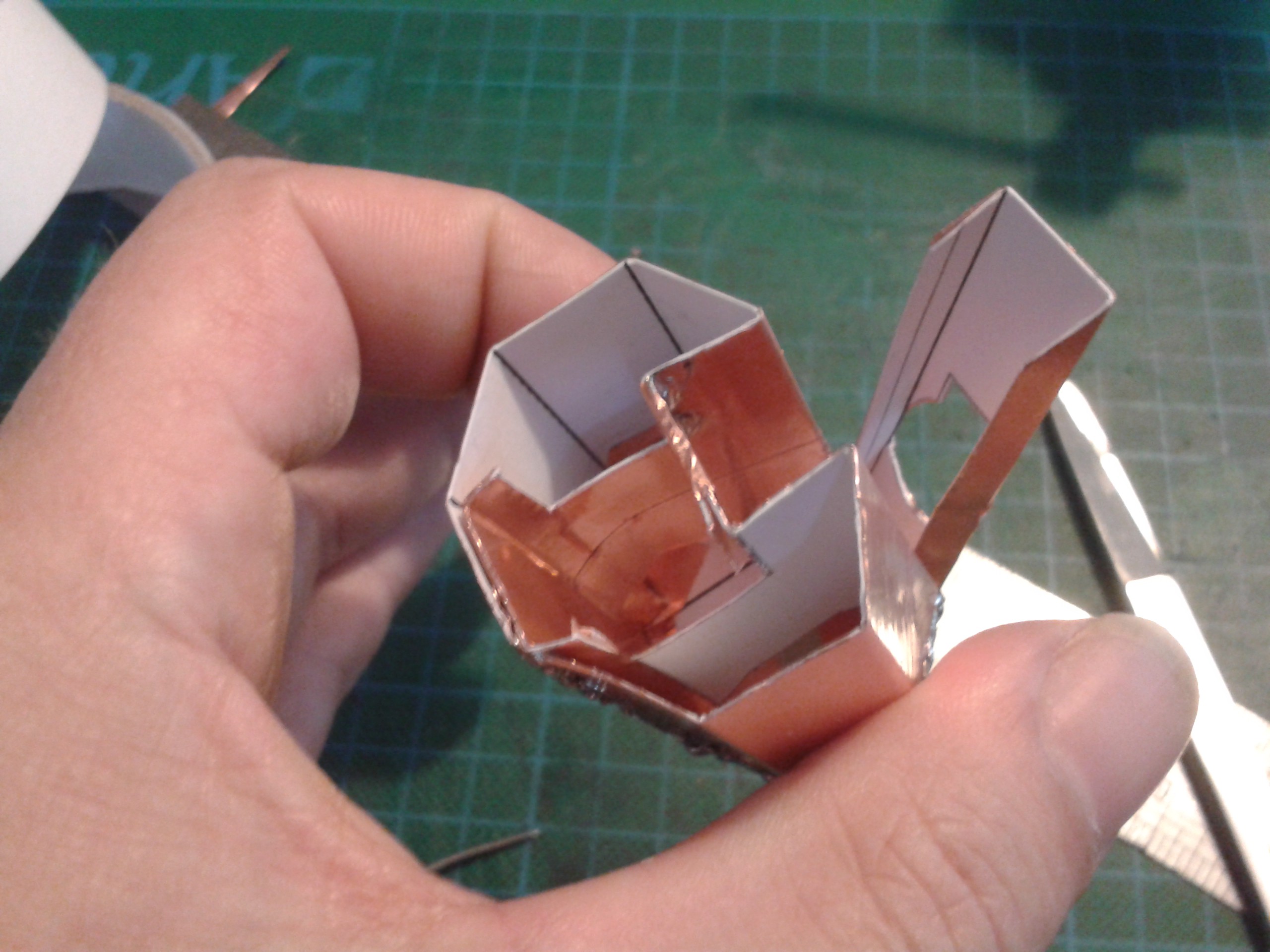
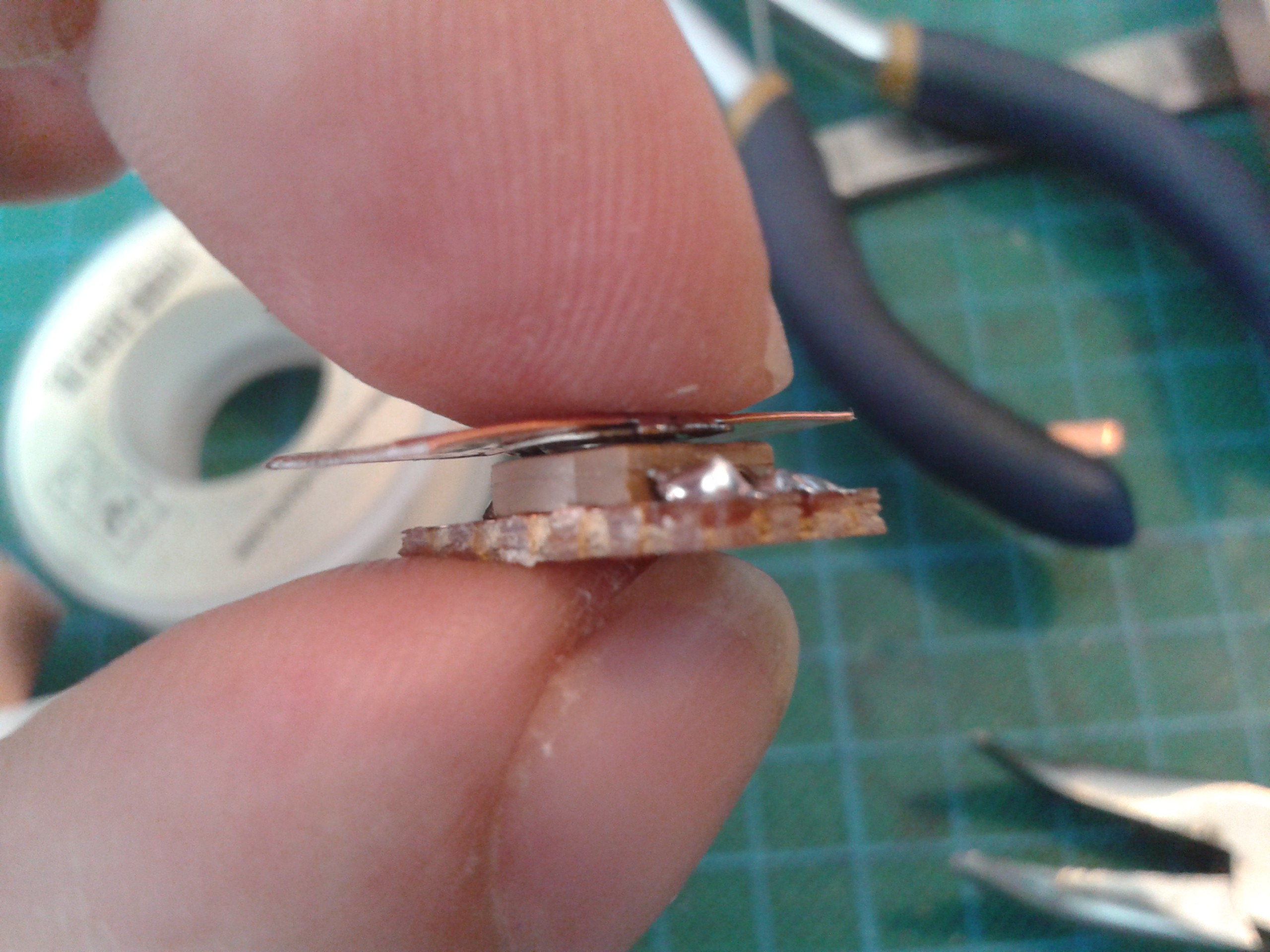
Following the theme of magnetics the battery snaps are also self setting. These are made with a spade terminal stuck to a magnet and then layers of copper soldered to the crimp (Quickly... Neodymiums denature and lose their magnetisation if you get them really hot...) before enclosing it all with a boot made of shrink tube with a hole cut in the edge.
They just adhere to the battery and make a perfect contact. I'll make caps to fit the ends better eventually.
![]()
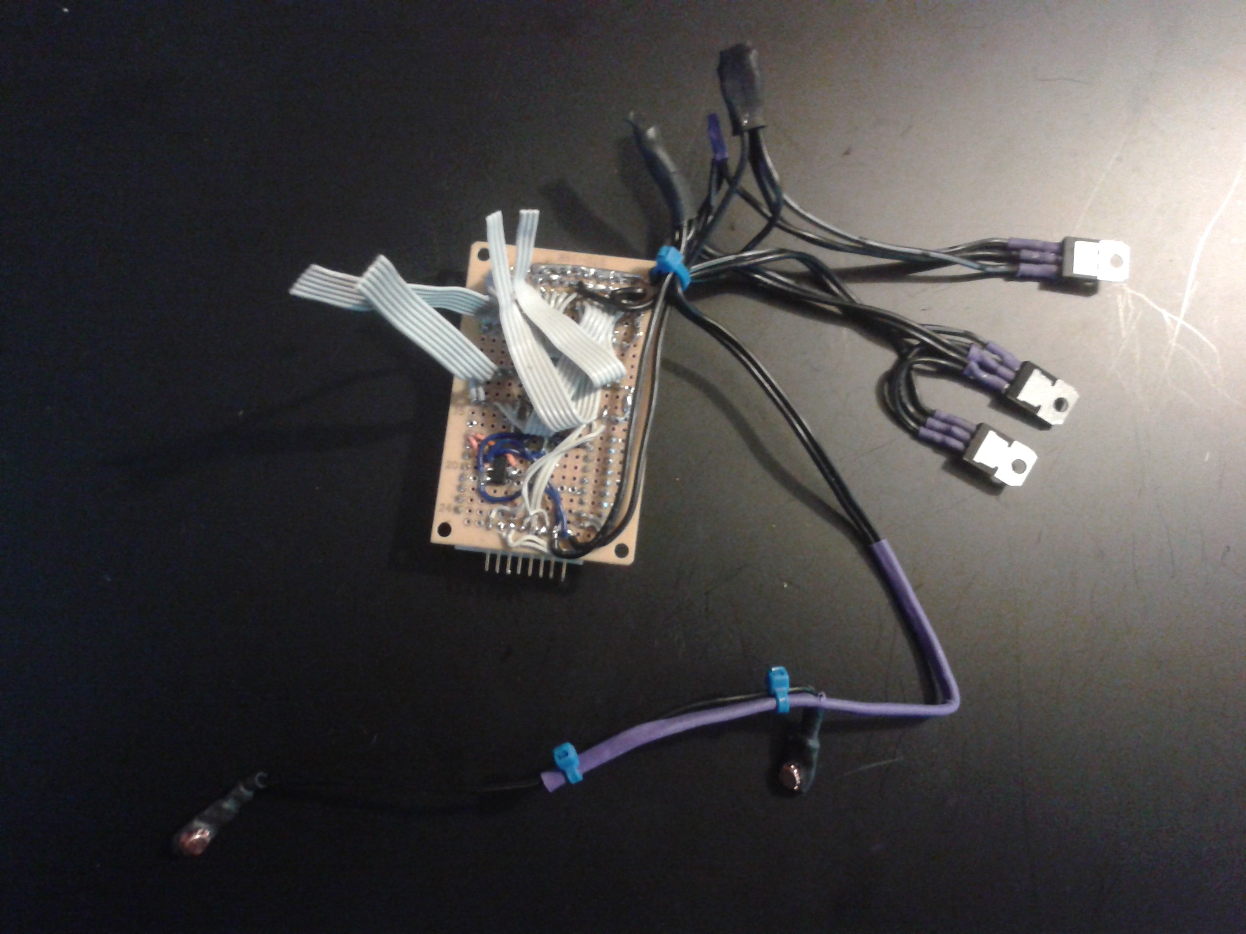
The servos need 6v and there's ten of them, it will probably cook one regulator so each leg has its own. I didnt have a spare 5v regulator for the brain so the separate regulator with the large boot on it is a LM317t with a resistor divider on a bit of board. They are all 1.5a so they should be enough.
![]()
The hips
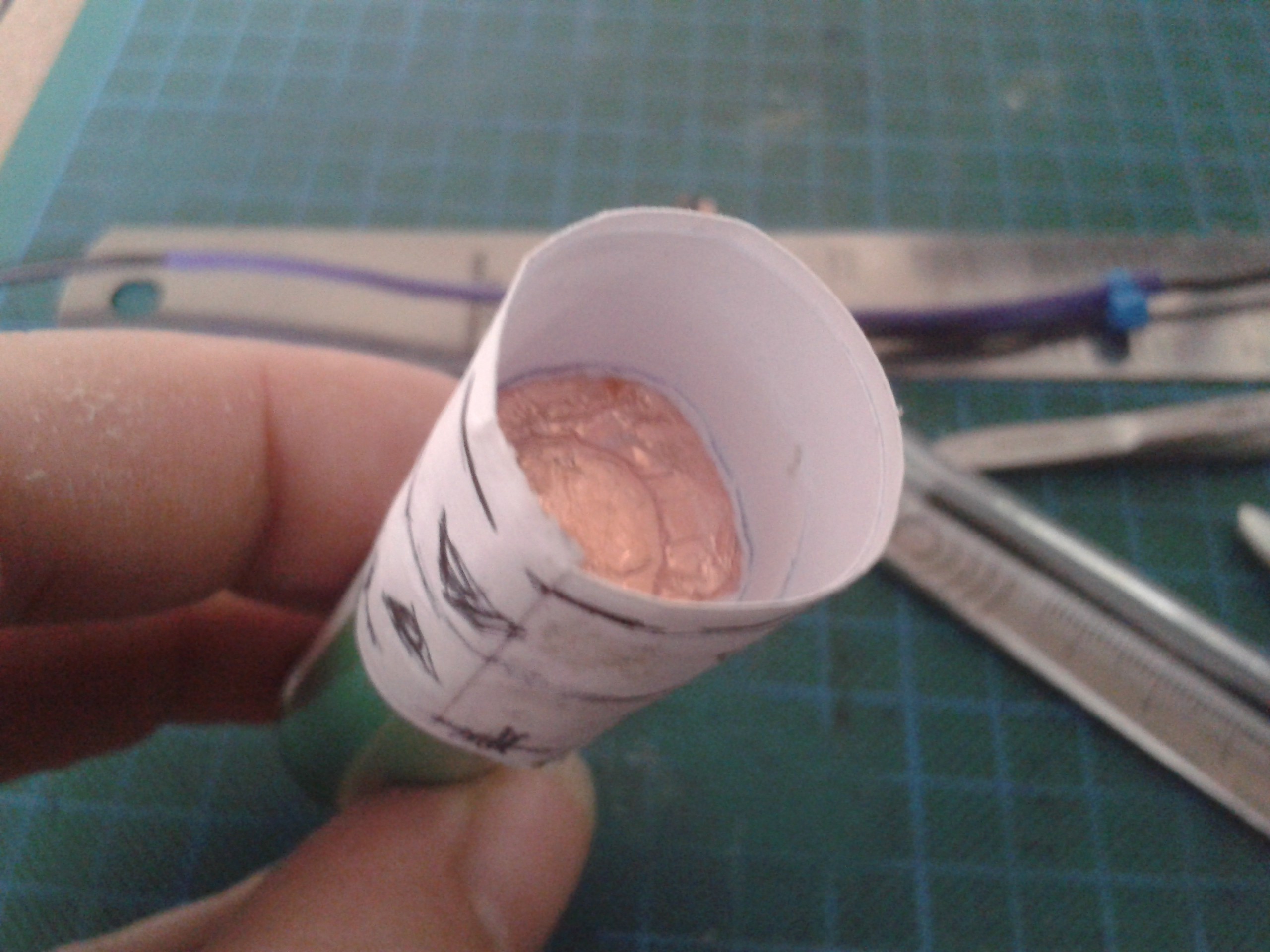
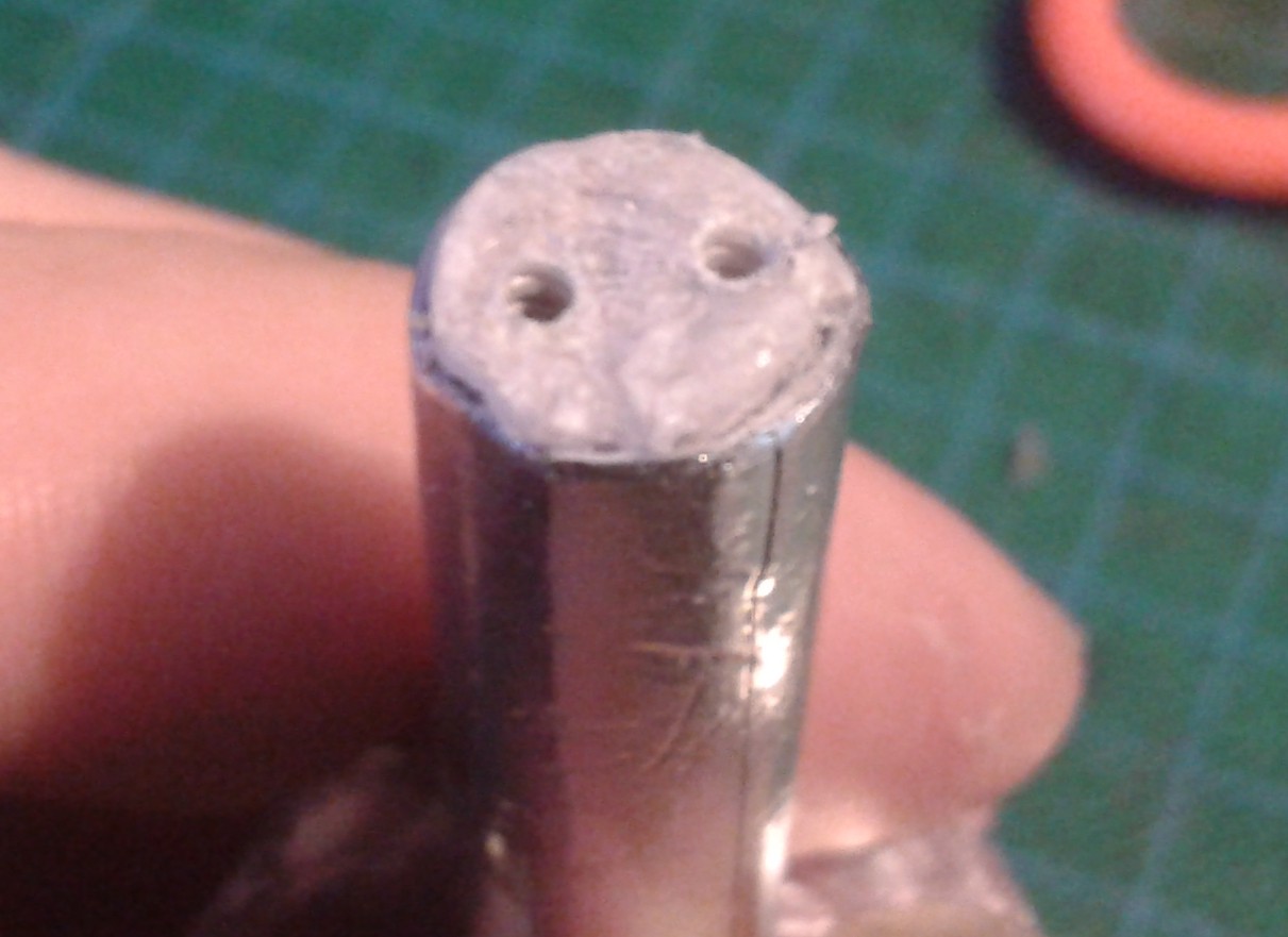
Plugging the tops of the hip bearing tubes proved easier than expected. I rolled up a piece of card really tight and stuffed it in the end of the tube until it jammed. Then I cut it off with a pair of sharp snips, nibbling round it until it went through. This left a furry mess, but a trim and 5 or 6 drips of superglue later its solid plastic, as the cyano wicks into the card and bonds it all solid. Be careful with thin cyano, this will get hot...
It doesnt require drilling, just start a screw with a sharp point and it winds in there like a champ.
![]()
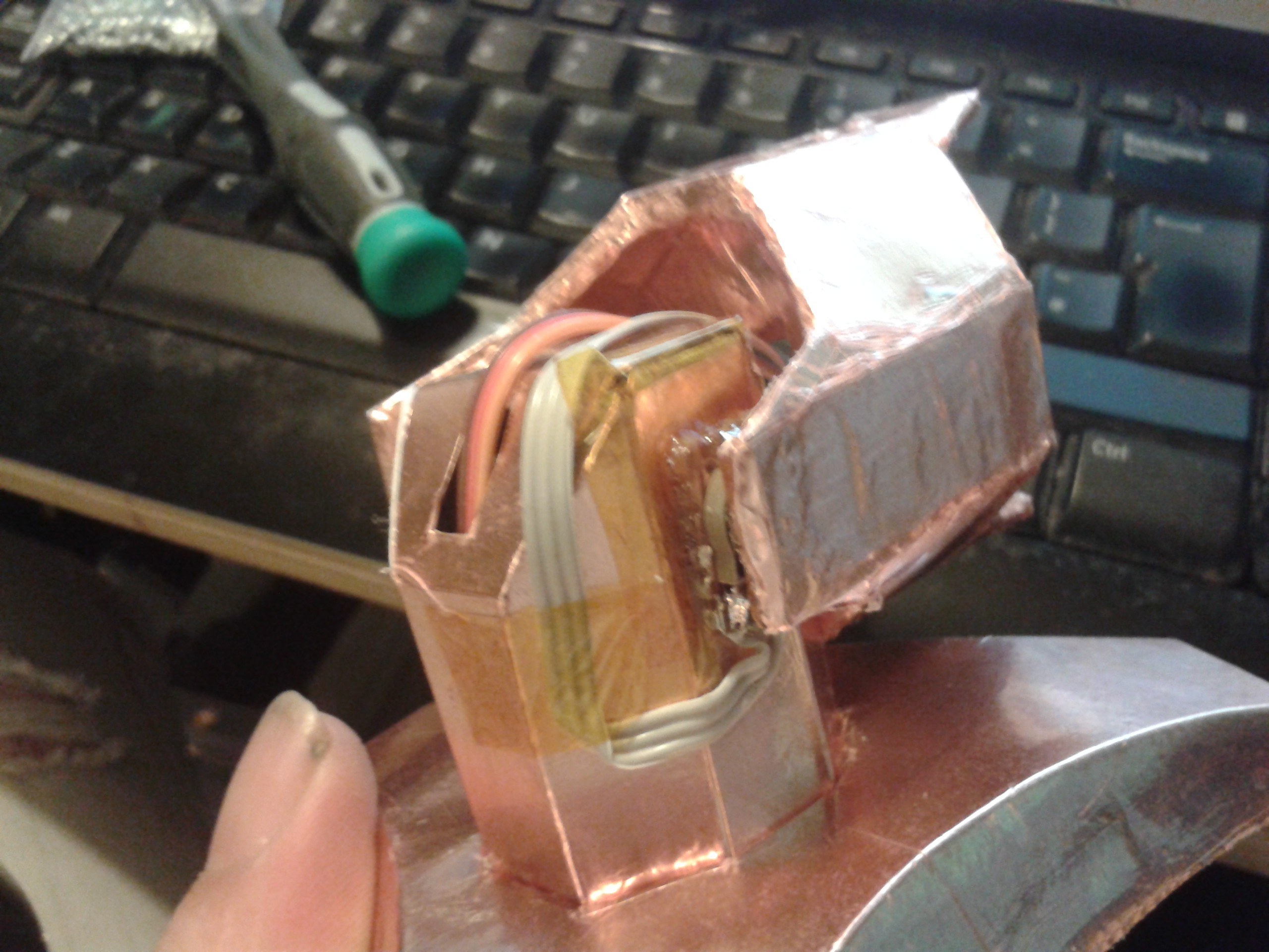
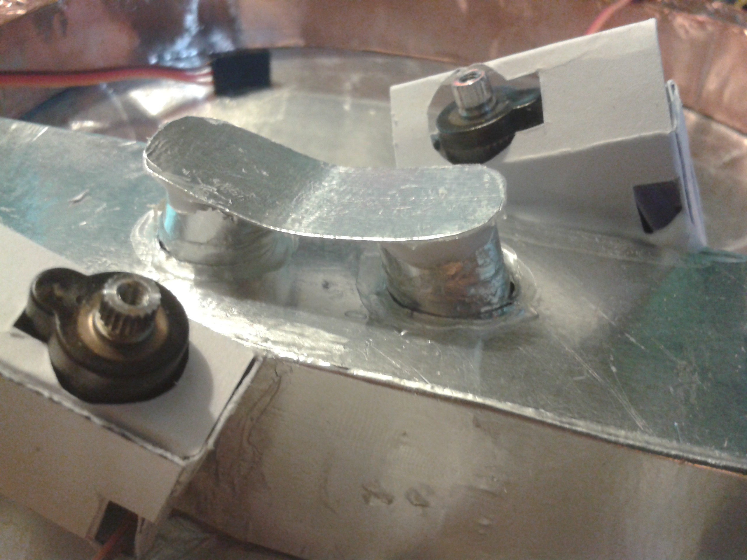
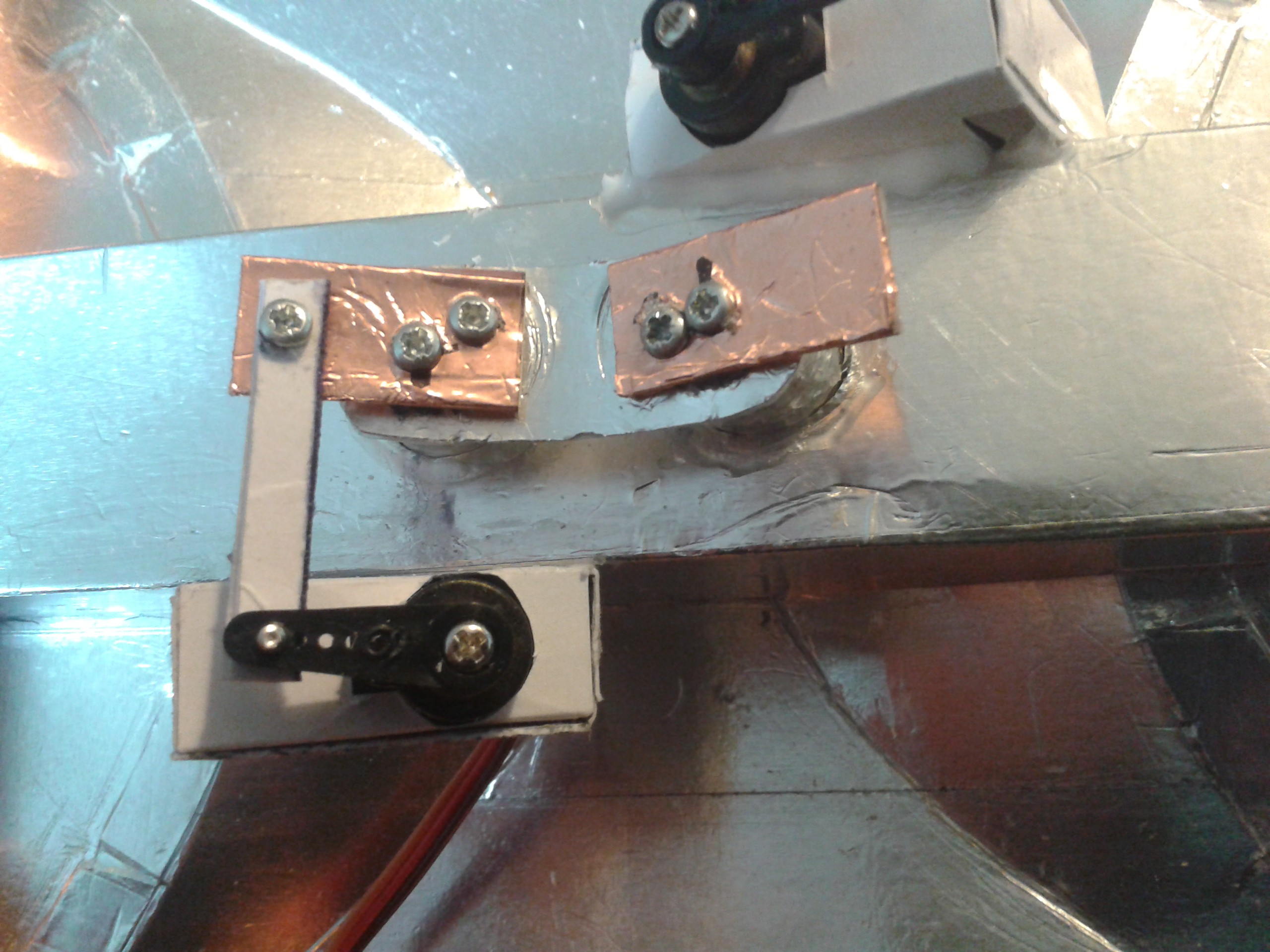
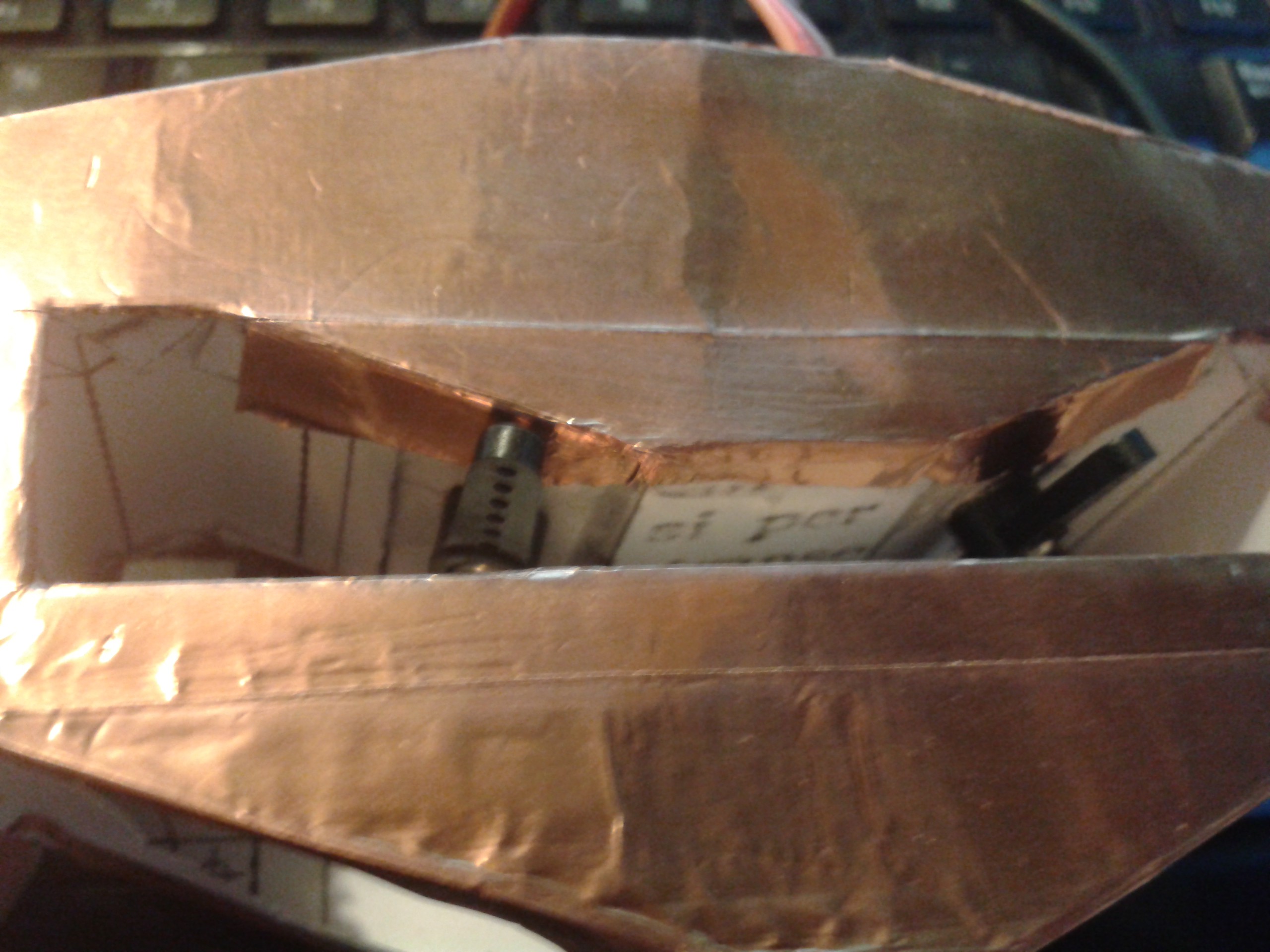
The tops of the bearing tubes are faced with a foiled surface, I cut out the tube tops with a scalpel as this is all on-the-fly and not designed in the computer and printed off. Note the servo box, this took a bit of lateral thought as the original flapped around, being an open-topped box. The lid braces the servo as well as stabilises the walls.
![]()
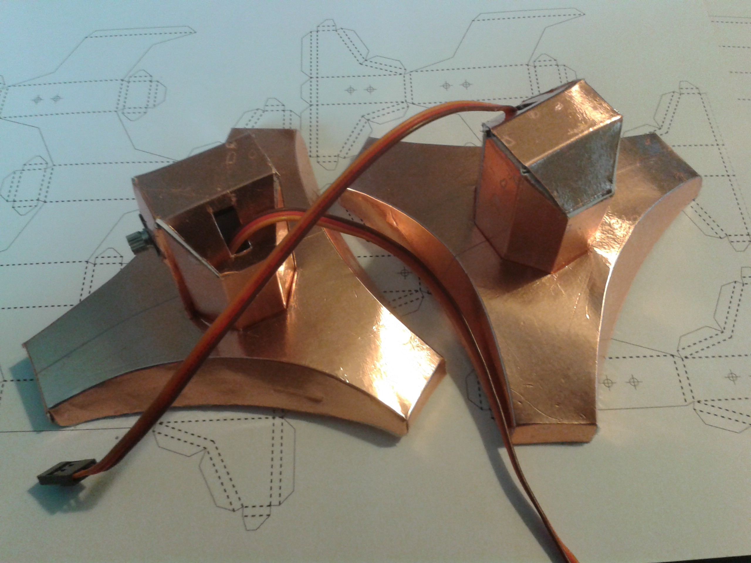
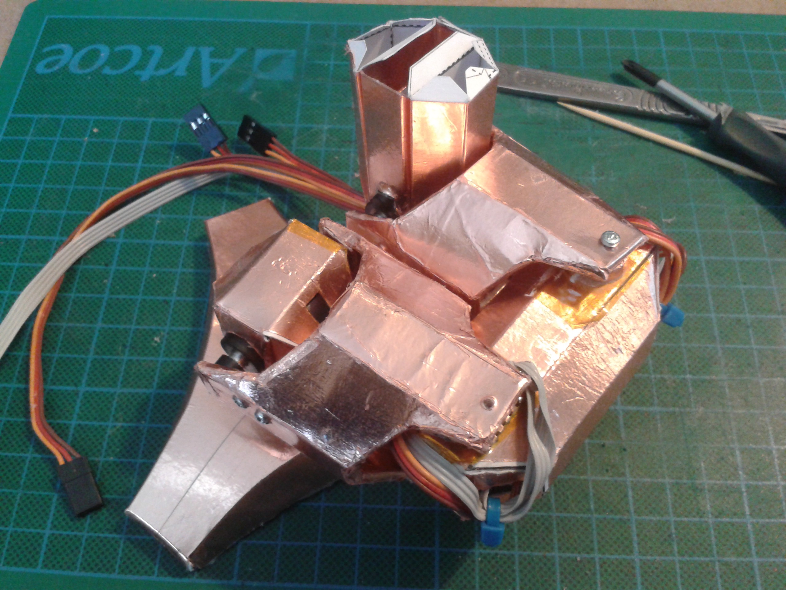
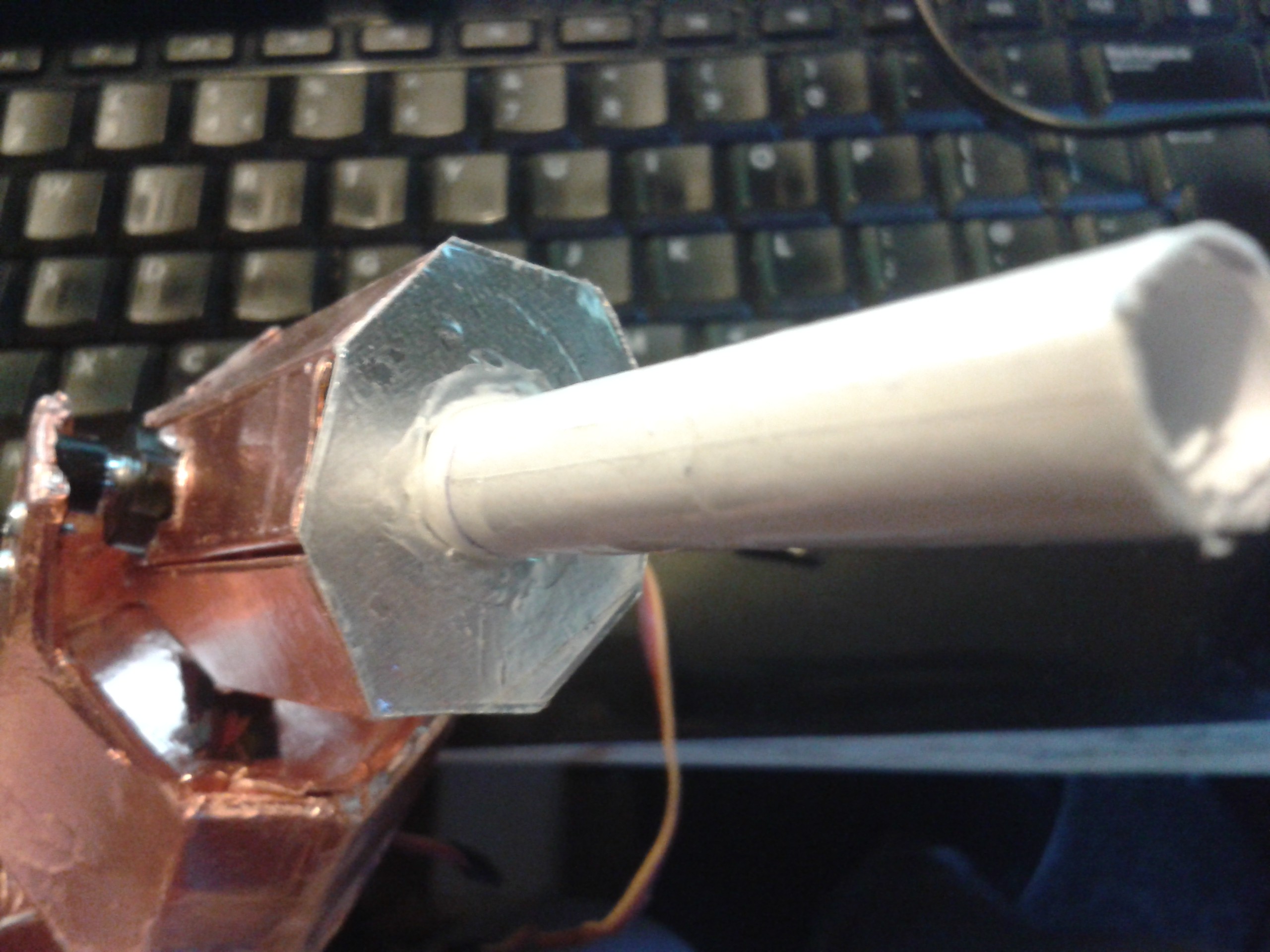
They have simple levers to drive the tops of the hip bearings. Ewww... Flapping canvas... That mechanism is older than I am, and both the servo and tube rotate in the same plane. Why are servos still boxes with levers? Bah!!! I cant make those tiny gear trains or I'd have hacked them a *long* time ago. ;-)
![]()
It works, however overly complicated it may be.
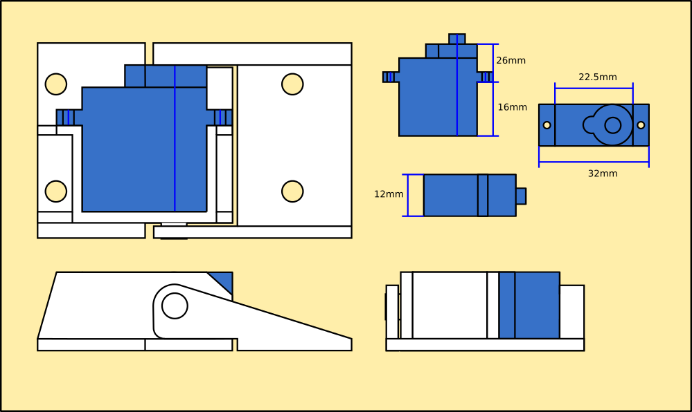
Both the lever parts are made by folding card into a zig-zag with 4 layers and soaking with superglue. They may as well be plastic, they behave like polycarbonate - flexible to a point but extremely stiff and strong. Also greaseproof, like plastic is and card isnt...
I'm going to use this in all the servo mounts across the system as it solves the problem of screwing those down securely.
![]()
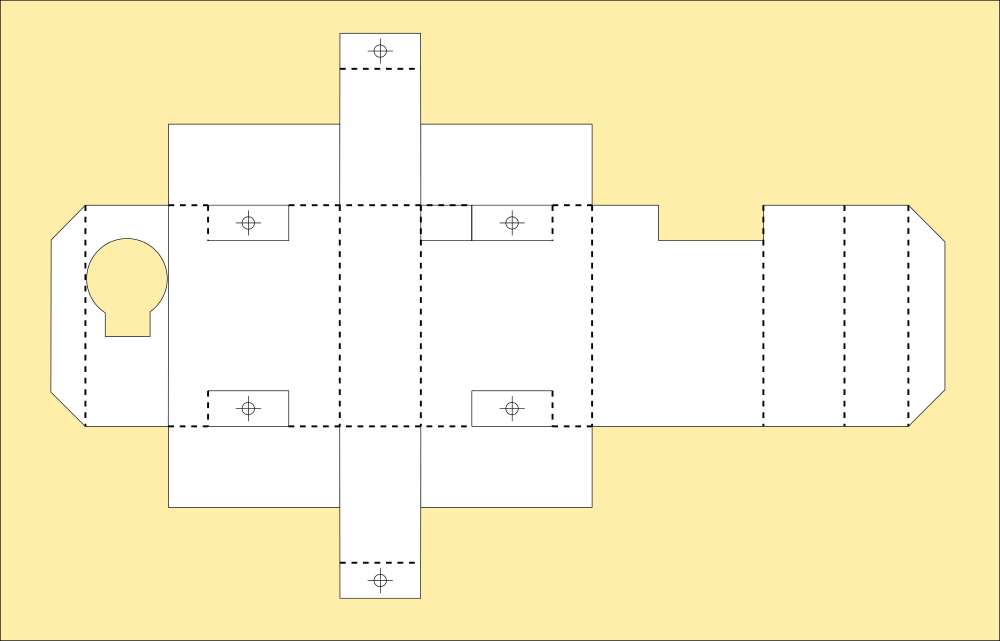
The servo box has been redesigned to have several layers for strength and mounts securely in the right place, lining up with the bottom of the chassis even though its just glued into place. Simply supergluing the servo tabs together is enough to make them rigid; they also have three layers and a vertical brace.
![]()
Next up, coding the OS and getting some movement out of it...
-
Sublimate of Monster
10/06/2017 at 17:55 • 3 commentsI've long had what I've come to describe as visions. Usually they are repetitive dreams, something I've had since childhood and have come to trust as portentious.
My robots I only built because I dreamed them up during childhood, or so I thought. But after some recent and rather disturbing flashes during my waking hours, that have coincided with real events like threads of a tapestry I've instead come to think I saw myself building them in a dream during childhood. Many other dreams have come to pass in a roundabout way too, eventually, anyway, the robots I have been waiting for especially.
I've almost done my bucket list, because of those dreams. Paint a portrait, write a sonnet, poetry, invent something or discover something scientific, pilot a boat (Live on one is still up there...), write a book (I'm saving that for last lol), raise children. And more, care for an adult (I assumed it would be a partner but nevermind), and become globally notorious for fighting dragons in my sleep besides a few other things. I've walked through fire to be here as well, and the only way to survive that is to learn the art of sublimation.
Well, having a vision of a flash of energy and some electronics right before a bomb goes off and makes it into the news would upset anyone, even if they are used to dreaming of things that come to pass. I cant paint this, turn it to music and it wasnt something I wanted to shout about. I wouldnt build or wield a weapon in earnest with these hands of mine either, so it has to go somewhere or I explode.
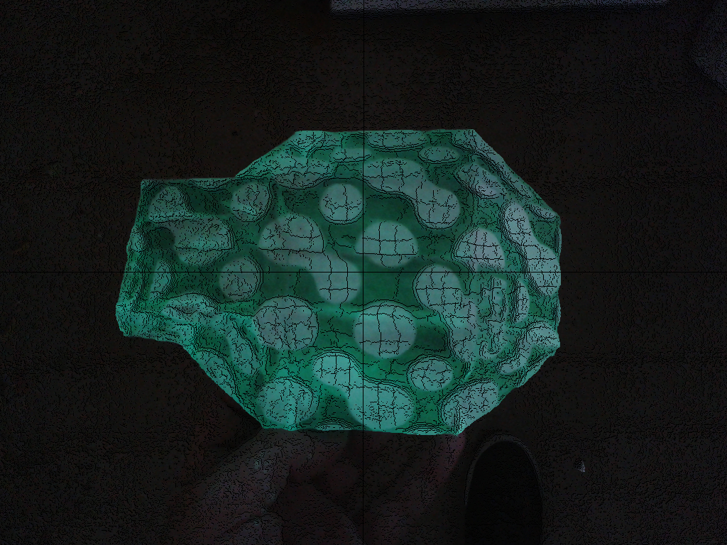
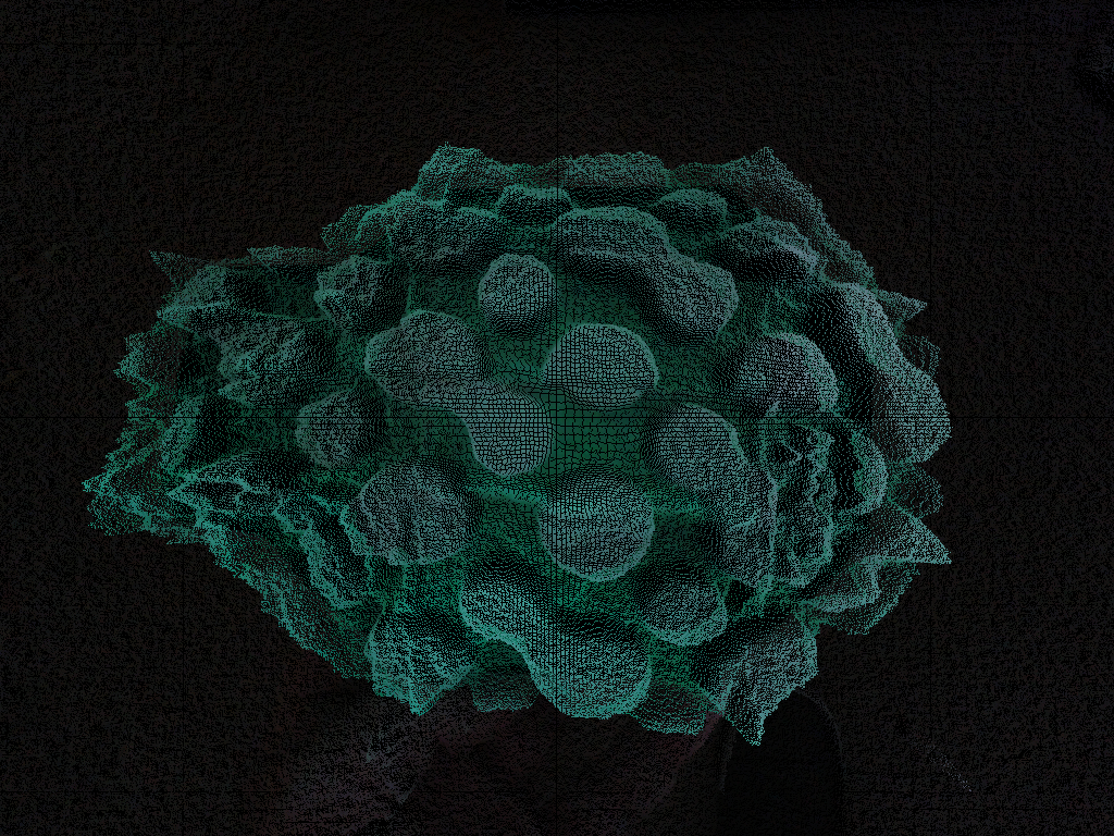
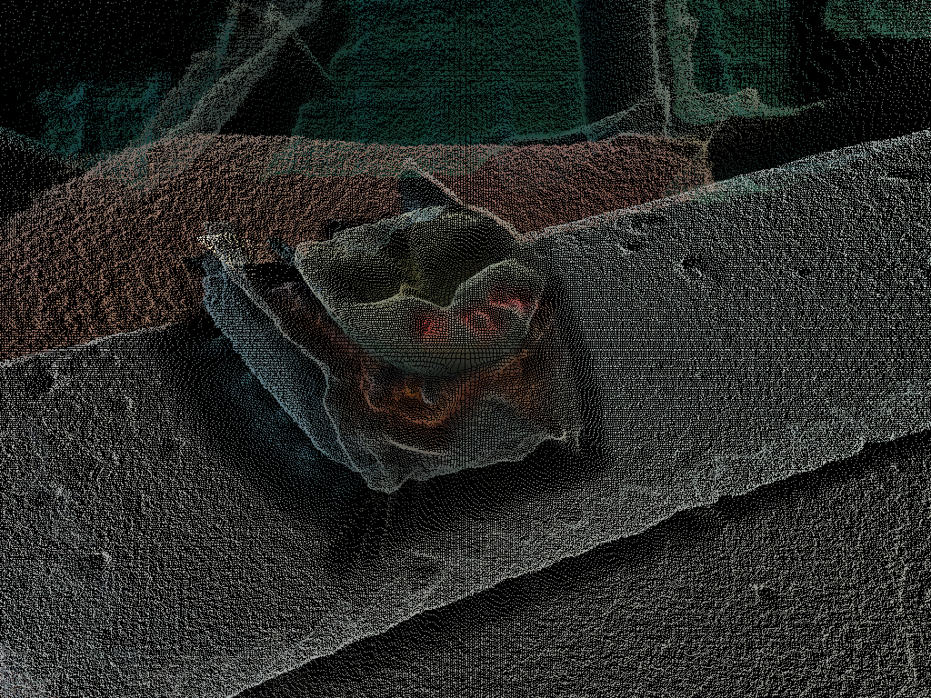
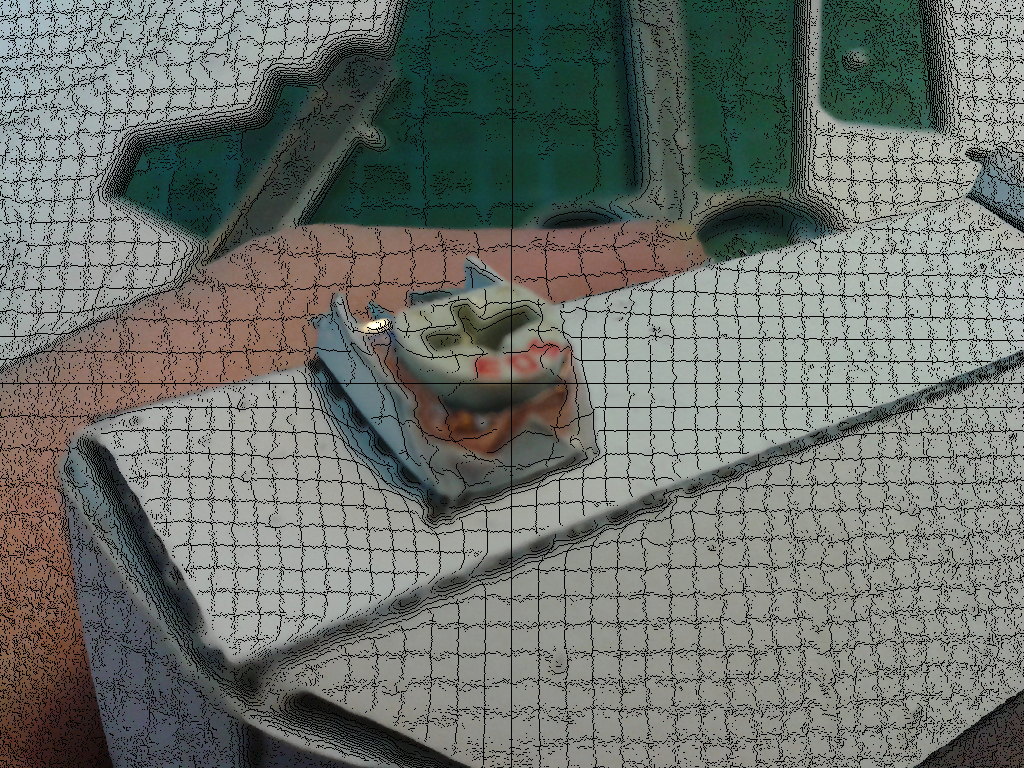
So, needing a photo-montage for the Prize video and lacking video editing software that plays nice with my hardware, I turned to a bit of mathematics and blew up my photos metaphorically.
Using histography and geometry the photos are broken into particles, accelerated off the display and then reconstituted into the next in a fluid succession. Unfortunately, YouTube has other ideas about what constitutes HD video and I cant post it in all its glory because of their compression mechanism. This is 2K video (actually 2048 pixels wide) after posting it to YouTube, cheers guys. Most disappointing... Its only this good because I tried using 4 YouTube pixels to one of mine but it took so long to upload I'm not going to try 4K.
I attempted to make a GIF of it, but that also wrecks the image and is too big to upload here anyway.
Here are some stills at the original 1024x768 resolution.
![]()
![]()
![]()
![]()
![]()
![]()
Every single one of those pixels is treated as a particle and thrown out into a cloud or nova before being reconstituted into the next photo based on its colour. Its all done by a Python script at the console the same as my #Old School Music Video except that the frames are produced from photographs rather than captured by AIMOS.
Thats 2,017,198,080 vectors to compute for the montage, and unfortunately YouTube can only display most of them.
![]()
-
Viu La Resistència
10/04/2017 at 12:44 • 0 commentsEverything seems to be made to fall to bits at the slightest provocation these days.
I saw an advert on TV featuring a graphic number of ways your mobile screen would need replacing, from leaving the phone on the car roof and driving off, to sitting on it while making out. Is that a phone in your pocket or are you just pleased to actually see me... Lol... Anyway, it wasnt an ad for a phone repair shop, it was a carrier advertising a free screen replacement with my new phone.
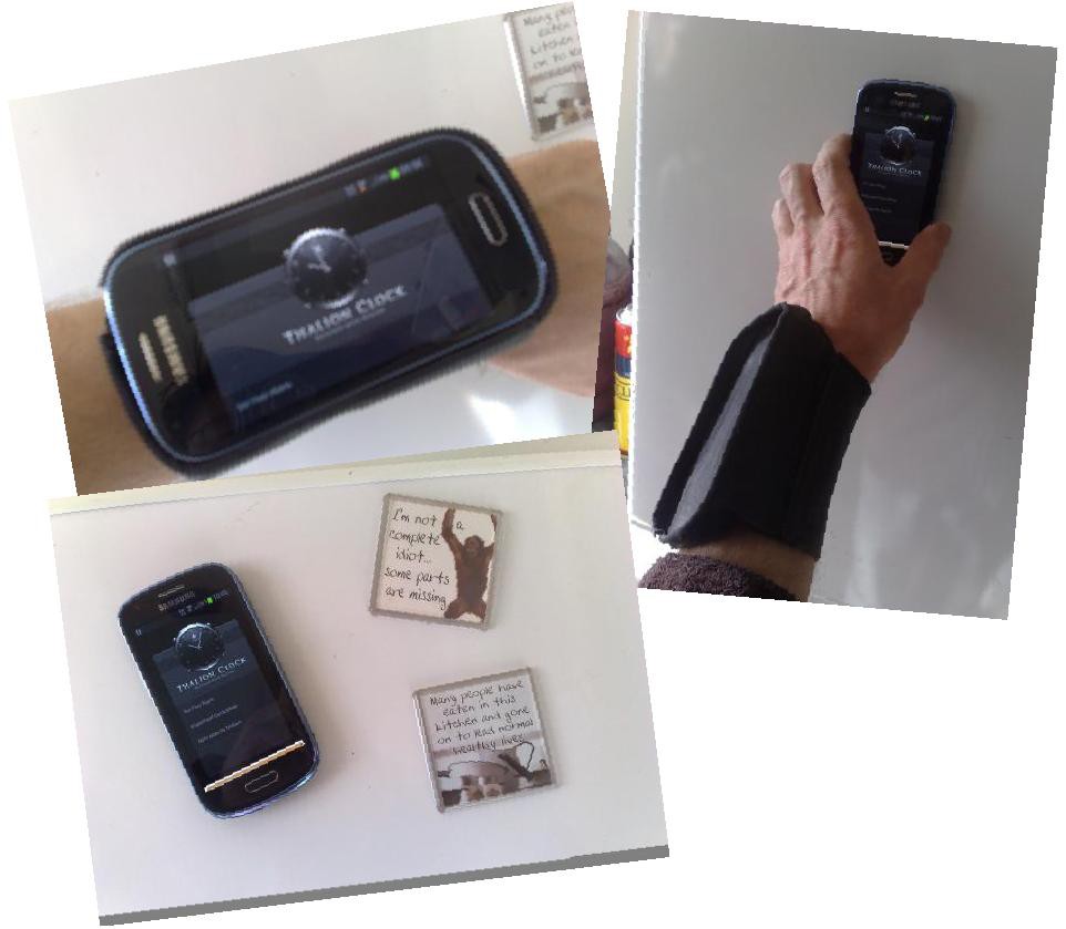
I'll keep my wrist harness thanks, the current Z3 is over two years old, paid for and still in near-perfect condition. I replaced the Galaxy S3 that preceded it because I took it out of the harness while moving furniture and put it in my back pocket, then landed on it going up a flight of steps. Oh well... It takes lovely pictures though, and remains cabled to my PC for documenting my work.
Last I looked, anything that needs free repairs when sold was broken before it was bought, hook line and sinker at that. Nightmare. It doesnt help that things are made of crap that falls apart, so even if the thought is there for end quality it makes no difference.
I've spent weeks waiting for orders, searching online and testing potentiometers to find something half decent;
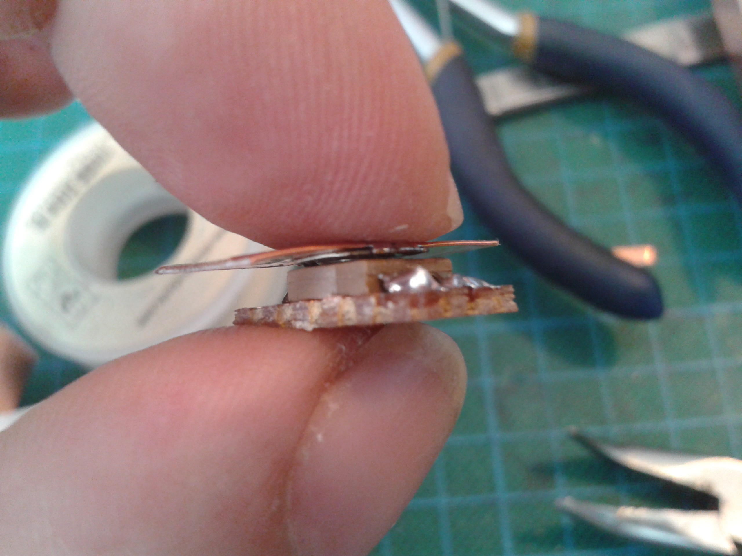
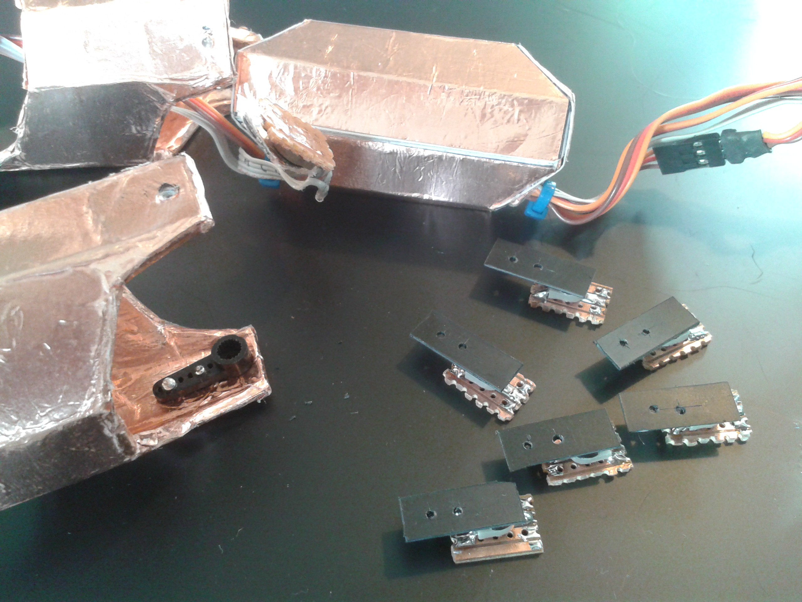
These things fell apart spectacularly quickly, they didnt even make it into service and broke during assembly. The rivet came out leaving the wiper soldered to the plate. There wasnt a lot of solder there, but its still stronger than the working parts...
![]() I had an awful lot of trouble with these too. After splitting the harvested ones I first tried by driving a screw into them, I bought some 'quality' ones and glued them to a bearer.
I had an awful lot of trouble with these too. After splitting the harvested ones I first tried by driving a screw into them, I bought some 'quality' ones and glued them to a bearer.![]() Unfortunately the glue capillaried up one of the channels and got on the track or wiper and locked most of them solid. Only a couple worked and those I freed off read open circuit.
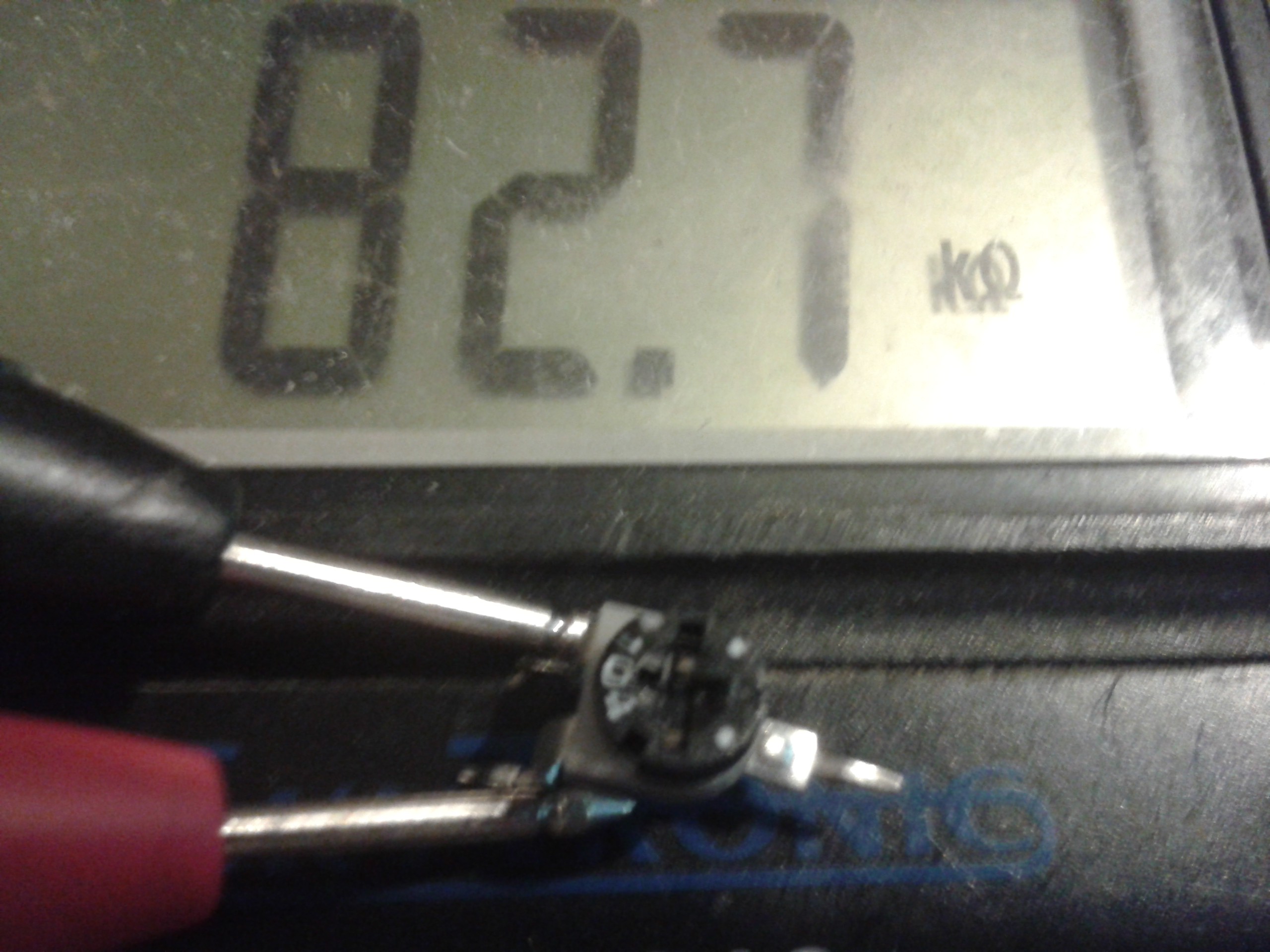
Unfortunately the glue capillaried up one of the channels and got on the track or wiper and locked most of them solid. Only a couple worked and those I freed off read open circuit.![]() Not that it made any difference really, they were advertised as 5% tolerance. Somebody couldnt count and I was pretty sure it wasnt me. They were all pretty bad except for one, which measured 99.7K. I suppose that constituted the 5% out of the batch that could be called within tolerance. Hmmm... This isnt what I call quality, those are K's its out by. Errors in hundreds of Ohms I can understand, but as a voltage divider that is utterly useless.
Not that it made any difference really, they were advertised as 5% tolerance. Somebody couldnt count and I was pretty sure it wasnt me. They were all pretty bad except for one, which measured 99.7K. I suppose that constituted the 5% out of the batch that could be called within tolerance. Hmmm... This isnt what I call quality, those are K's its out by. Errors in hundreds of Ohms I can understand, but as a voltage divider that is utterly useless.![]() I shopped around a bit. The one on the left looked promising until I discovered sneakily soldering those tabs to the wiper plate and then to a plate left specks of flux all over the track so it had dropouts in it. I couldnt clean them up and all but gave up.
I shopped around a bit. The one on the left looked promising until I discovered sneakily soldering those tabs to the wiper plate and then to a plate left specks of flux all over the track so it had dropouts in it. I couldnt clean them up and all but gave up.![]()
I remembered there is already one in the servo, and I had resigned myself to the possibility of ripping out the servo circuit and driving it off the processor via an H-Bridge up in the chassis and cabling the motor and potentiometer. I pulled some broken ones apart for the motors and had a look to see if they were harvestable instead. They arent any stronger than the others, and rely on the servo shell as a bearing as well, I couldnt just cut them down and solder a plate to them.
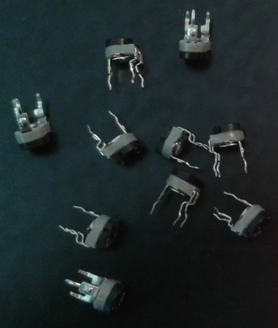
![]() While I was looking online I discovered a previously unknown description for them. I'd tried potentiometers, variable resistors, trimmers but hadnt thought of Presets. Thats what these are apparently. And Squires had them in stock, so I got them local too.
While I was looking online I discovered a previously unknown description for them. I'd tried potentiometers, variable resistors, trimmers but hadnt thought of Presets. Thats what these are apparently. And Squires had them in stock, so I got them local too.![]() At last something solid that I can keep glue out of and find an interface for! I shaved off the bezels so they would lay flat on the cardboard and covered the backs with metal tape before turning to my favourite metal of all to build something to turn them with. Something that I could also secure to a flat surface.
At last something solid that I can keep glue out of and find an interface for! I shaved off the bezels so they would lay flat on the cardboard and covered the backs with metal tape before turning to my favourite metal of all to build something to turn them with. Something that I could also secure to a flat surface.![]()
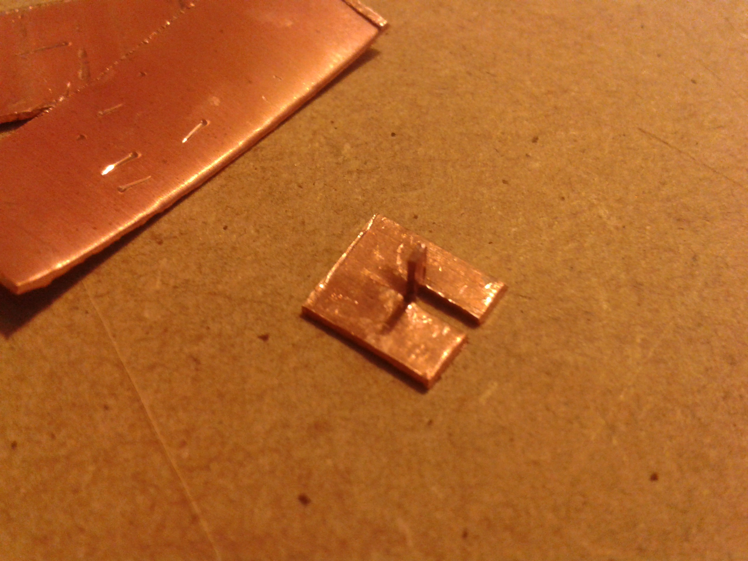
That works like a charm, although I did have a bit of a hiccup halfway through assembling the rest... They were bought as a batch, all from Iskra, all 100K presets and all pretty much identical (even the tolerances were close) except for one vital feature.
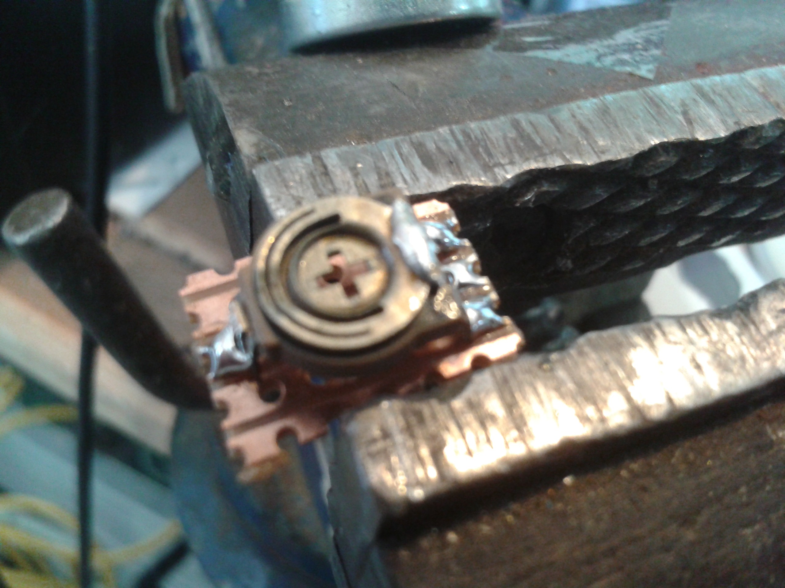
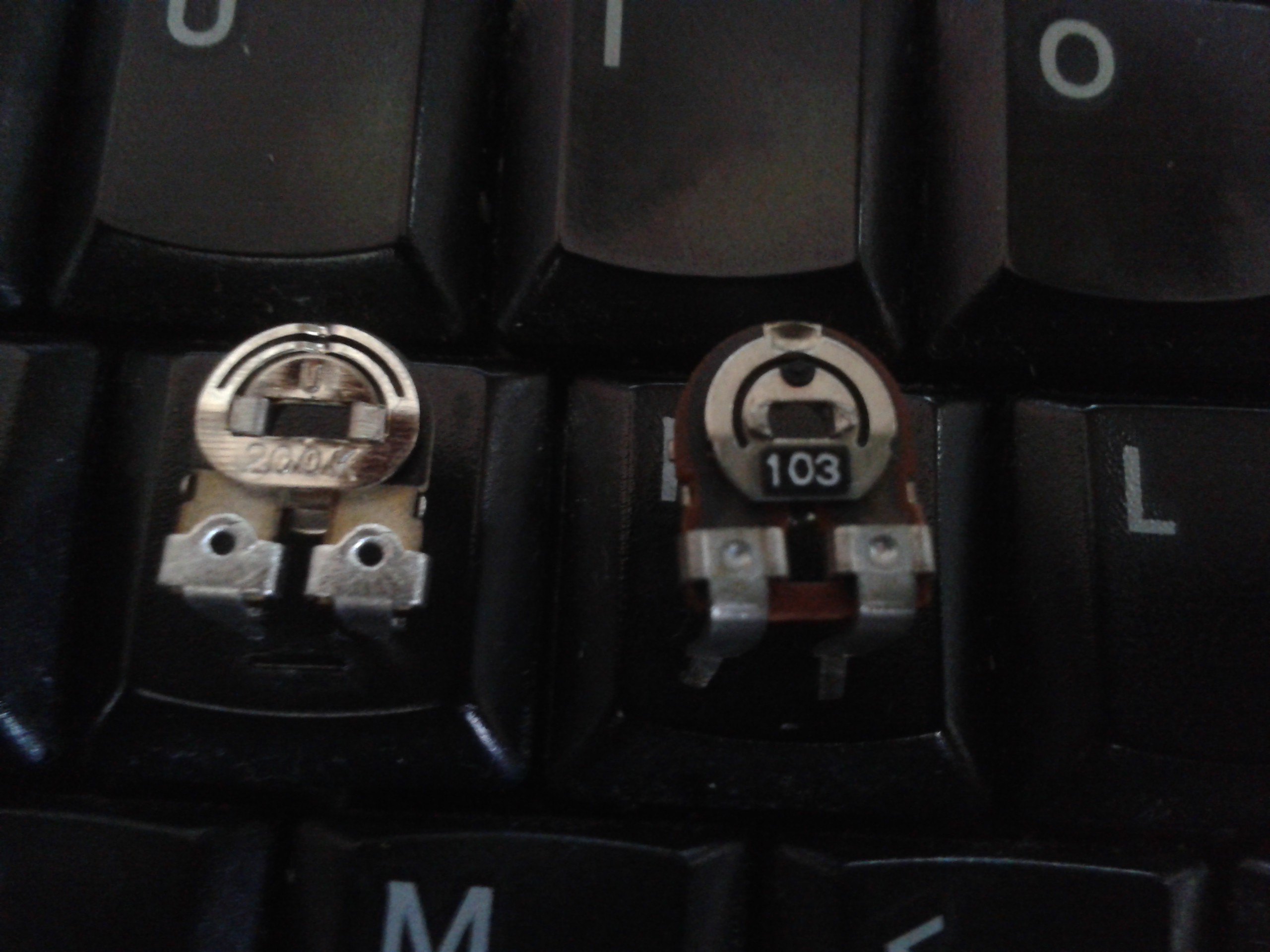
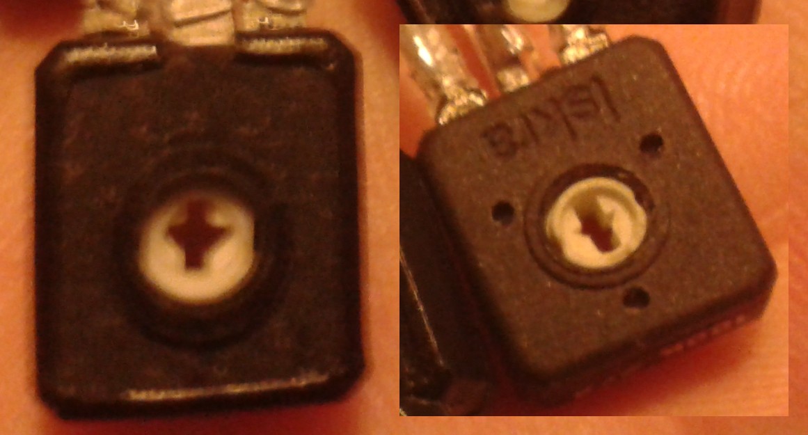
![]() The copper pin didnt fit the slot quite right and there was a little bit of play so I fitted it across the arrow instead. That worked a treat until I got to number 4 and discovered the remaining half werent completely identical. There's two different types of arrow... Nice one, Iskra. I dont know which is the old spec, but I think it may have something to do with the one on the right being impossible to read without magnification let alone in a dark recess lit by the backs of LEDs. I just hope thats the old one. A bit of filing sorted it out anyway...
The copper pin didnt fit the slot quite right and there was a little bit of play so I fitted it across the arrow instead. That worked a treat until I got to number 4 and discovered the remaining half werent completely identical. There's two different types of arrow... Nice one, Iskra. I dont know which is the old spec, but I think it may have something to do with the one on the right being impossible to read without magnification let alone in a dark recess lit by the backs of LEDs. I just hope thats the old one. A bit of filing sorted it out anyway...![]() And it fits even better than all the trimmers, some of which worked out over 6mm high with the circuit board to mount them. These are under 5mm high.
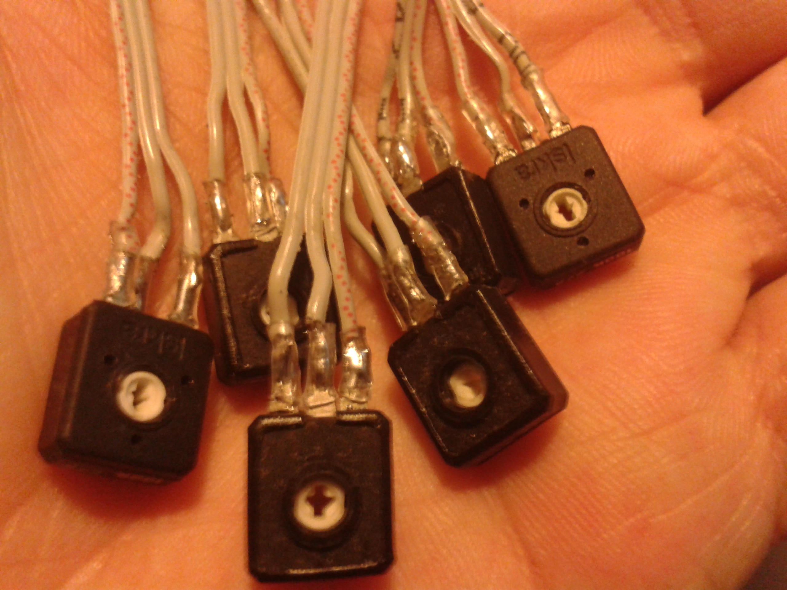
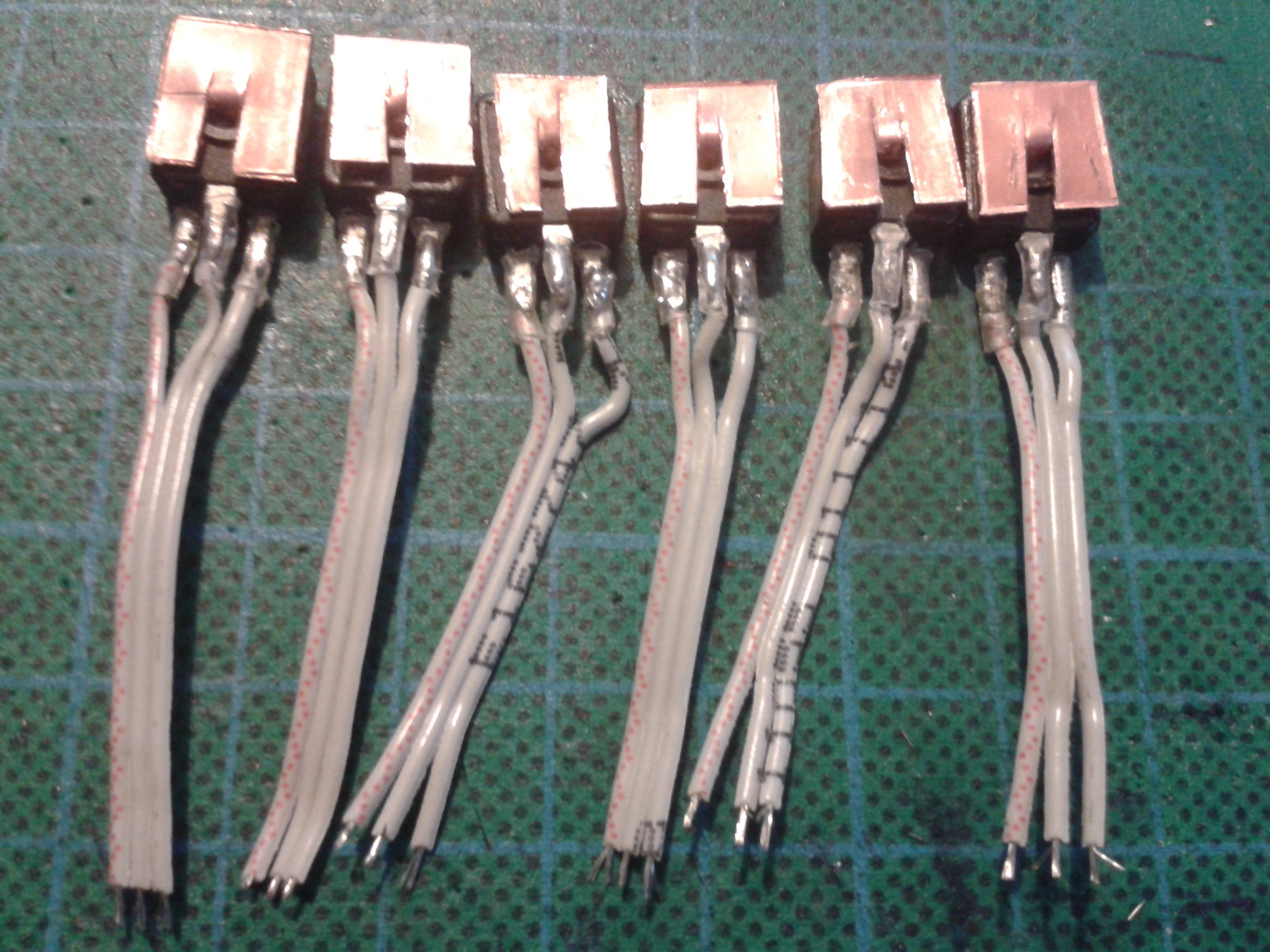
And it fits even better than all the trimmers, some of which worked out over 6mm high with the circuit board to mount them. These are under 5mm high.![]() A bit of wiring later...
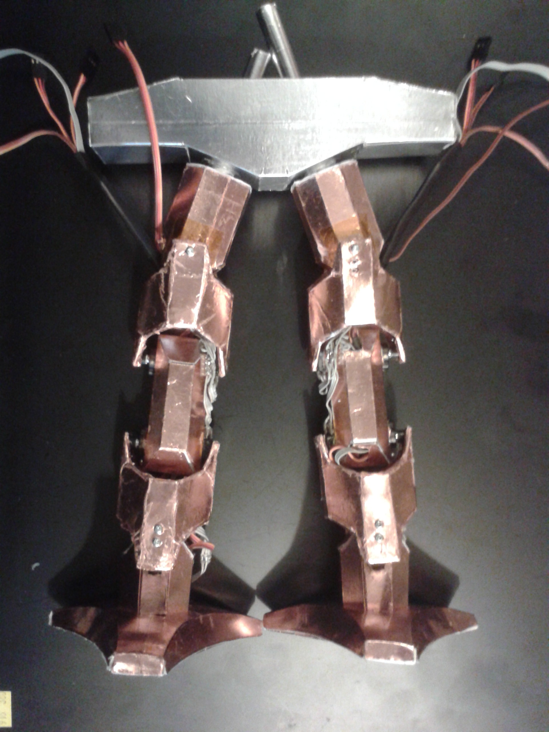
A bit of wiring later...![]() Thats got the limbs reassembled with working angular sensors, and without having to take apart a brand new set of servos. I may have a go at hacking these at some point after reading Radomir's #Ensmarten Your Servos
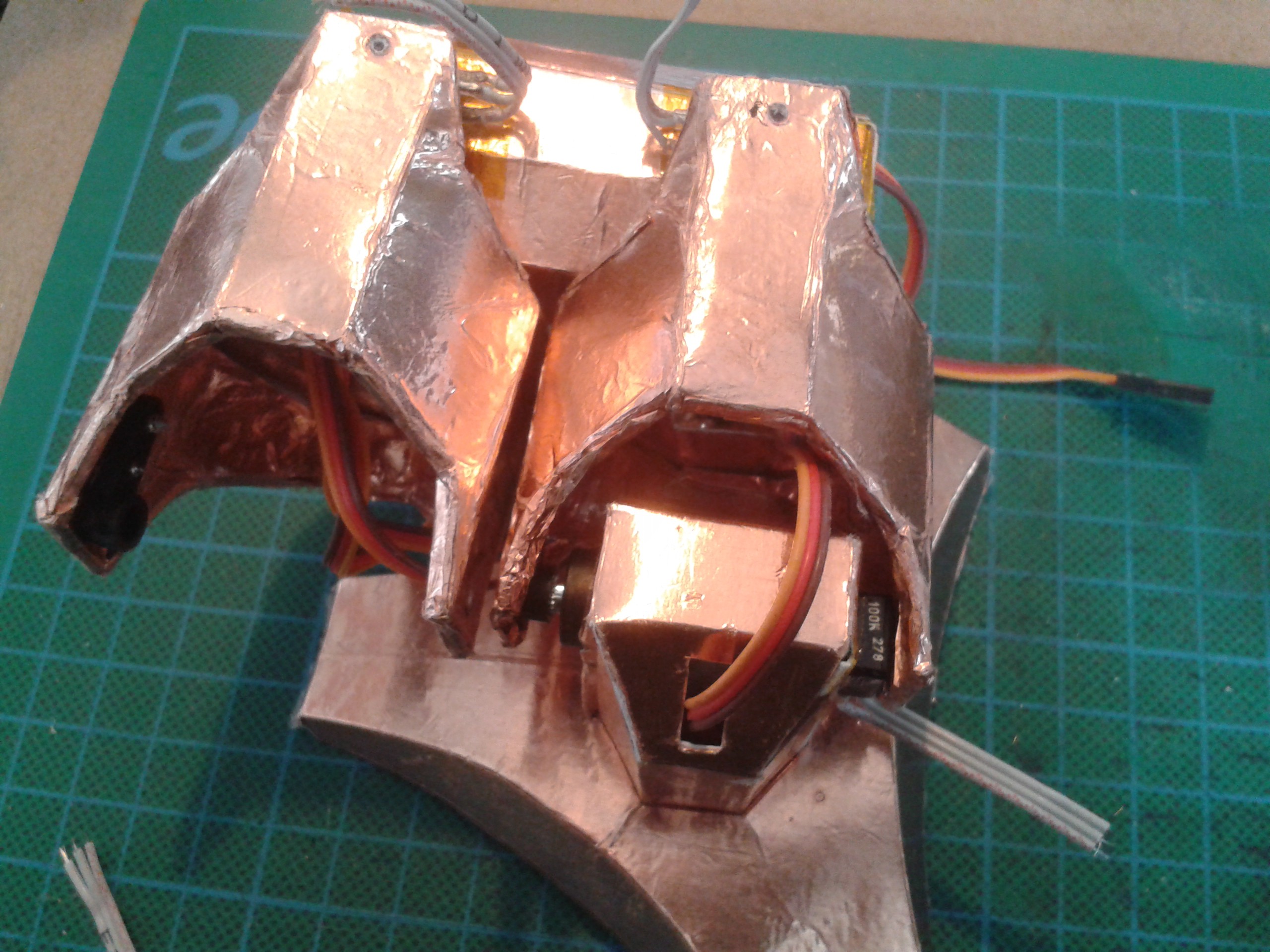
Thats got the limbs reassembled with working angular sensors, and without having to take apart a brand new set of servos. I may have a go at hacking these at some point after reading Radomir's #Ensmarten Your Servos but I'm not entirely happy with the idea of buying broken new hardware and hacking it. Servo's are older than I am, moan, whinge, etc.. ;-)
![]() I also had some servo trouble at the top end and had to redesign the interface to the tops of the limbs. They were driven directly by the servo shaft, but limitations with the materials and the rather ancient design of the mountings meant I had to fall back to the barbaric practise of chassis-mounts and push-rods. Every time I see that mechanism, I also see flapping canvas and flying-ace goggles spattered with engine oil, followed by a plume of smoke. :-D
I also had some servo trouble at the top end and had to redesign the interface to the tops of the limbs. They were driven directly by the servo shaft, but limitations with the materials and the rather ancient design of the mountings meant I had to fall back to the barbaric practise of chassis-mounts and push-rods. Every time I see that mechanism, I also see flapping canvas and flying-ace goggles spattered with engine oil, followed by a plume of smoke. :-D![]() The bearings are made from 'paper metal', which has turned out to be another interesting and useful hybrid of materials. The rods for the thigh pieces are made by wrapping a sheet of paper around a metal rod and securing the end with a piece of metal tape several layers deep. It is burnished with a piece of dowel before being wrapped with another piece of metal tape glue-outwards. Finally this is wrapped in a sheet of paper and secured with more tape. The resulting bearing and shaft set weighs very little, is as strong as plastic, fits perfectly and can be greased to further extend the life of the working surfaces, which are all-metal.
The bearings are made from 'paper metal', which has turned out to be another interesting and useful hybrid of materials. The rods for the thigh pieces are made by wrapping a sheet of paper around a metal rod and securing the end with a piece of metal tape several layers deep. It is burnished with a piece of dowel before being wrapped with another piece of metal tape glue-outwards. Finally this is wrapped in a sheet of paper and secured with more tape. The resulting bearing and shaft set weighs very little, is as strong as plastic, fits perfectly and can be greased to further extend the life of the working surfaces, which are all-metal.Amazing what you can make with a sheet of paper and sticky tape.
![]() All I have to do now is trim that up, plug the tops of the tubes with something I can screw a lever to, and then mount the servos as per a model aircraft. Shudder...
All I have to do now is trim that up, plug the tops of the tubes with something I can screw a lever to, and then mount the servos as per a model aircraft. Shudder...
I have had time to make a lid while I was waiting for parts, in between catching up on other projects. I used the MorningStar maths for this, as that is what it was originally intended for. ;-)
Wiring is next, and Ars' #ZeroPhone - a Raspberry Pi smartphone also provided me with a battery solution; I had to buy some anyway and I can just run voltage regulators off pairs of these in series:![]()
Anyone remember Batteries Not Included? :-D
![]()
-
A Brief Interlude in Time
08/28/2017 at 09:35 • 0 commentsTime is an interesting concept. Formless and ever-changing as we drift through it, but it's a hard dimension like any other, including the other three we know and love.
X,Y,Z and T sit in another set, some of which are co-planar and some of which cut them, leading to various effects we can perceive, and I gather there are 11 of them in total. Energy itself is a dimension; a torsion or a slope we are not aware of that can twist matter around an axis until it breaks, leading to all kinds of trouble as matter is formed of packets of it sitting in a well. Distort the well, the container, enough and the energy spills. Its material form relies on the shape of the container - information that is stored in dimensions other than the ones we can touch - and as matter is simply a collection of identical units in an arrangement it's fairly obvious how this works. XYZ are hardware, T and the others are software that make energy do something by intersecting with the well and applying force on it to give it form. Arranged energy...
There is only only universe (that we are aware of), which is why it's called a universe. It's unitary... Because it is all there is there must be nothing else, so surrounding it must be infinite nothing, or, it is itself infinite.
This latter theory bothers me greatly, all of our physics only works with the concept of totality, in which infinity is by nature incalculable. It blows a nasty big hole in the idea that we can grok the universe by taking it apart and summing the parts for their difference, the only way we know to discern arrangement from inside the well. If it goes on forever, so does the amount of energy available to configure.
Thats a bit like building a calculator that only goes up to a thousand; you may as well not bother using it for anything substantial, like figuring a universe. One may as well believe God made the lot with his bare hands, and its not for me to say he didnt either.
So I suppose the buzz is infinity does indeed have a beyond in either case. ;-)
Perception of the well
If the universe really works like that then we are looking at it all wrong. The train of thought is that we are surrounded by the universe and it spreads out in all directions because we are inside it. That's constrained three-dimensional thinking though. Objects only have a top and a bottom, front back and sides because they are three dimensional and thus contain their inside, they have boundaries. If you want evidence that there is more, we cannot explain fields in these terms; these intersect matter using somewhat arbitrary rules, have no boundaries and dont even appear to rely on it's presence at all.
If you take an object that is hollow and has an opening, you can turn it inside out. This again is dimensional thinking. If you imagine a cup with a projected image on it, the image can slide up the inside, through the inside and down the other. It doesnt actually have an inside at all, its a single plane surface wrapped into the shape of a cup and could equally be a solid sphere of clay. This of course would not contain water in it's well because it doesnt have one and it's only the dimension of gravity - which direction and strength - that defines an inside in relation to it.
There's a class of shape that defies this rule, known as a parahedron. A cube is a simple one, and demonstrates the properties easily:
It has 6 faces, each of which has four sides that each share a pair of vertices, meaning the faces each have two neighbours. To flatten this out requires separating some of the faces from each other. Obviously if you separate them all it falls into squares, so there is a logical minimum of breaks you can make keeping a single plane and still make a valid cube from it. There has to be at least two faces sharing two others for this to happen.
![]()
Neither of these will fold into a cube for example, but this will.![]()
And so will any of these, with any one red and blue square. There are others, but they all share the same properties.![]()
The Perimeter of a tessellated cube is the same as it's manifold, and it is one-dimensional. It has no height or width but it does have length. Because the cube is a three dimensional object the manifold describes a hyperplanar trajectory across it's surface while retaining its planar form so that the length is accommodated.
Our universe is a skin with a manifold in the same way, and we live in that manifold. Everything on one side of the interface is past, everything on the other is future and the interface, which is always in motion, is the present. This is how the future and past appear to be the same, but one hasnt happened yet, and in between is the now joining them together.
![]()
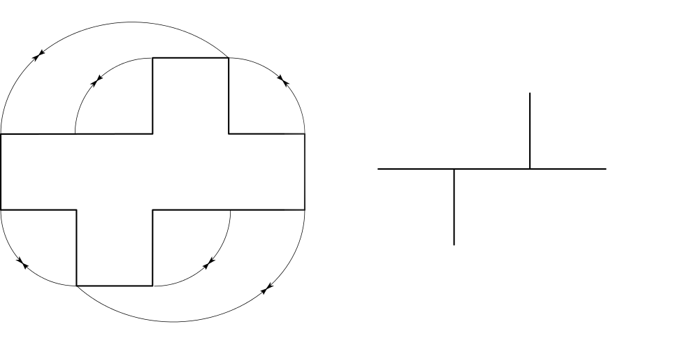
The interface looks like this in a cube formed from a plane like on the left. The figure on the right shows it as a manifold - a single dimension surrounded infinitely by its other two. The universe's three dimensions also behave this way, and the manifold is the part we touch and see. Obviously that manifold can be any physical shape, so long as it's dimensions remain the same the manifold is completely unaware of this.
Because the universe is curved and not cubic like our coordinate systems we measure points between it in a straight line, but this doesnt actually give real distance. You might think that equidistant points on the surface of a sphere are the same distance apart but they may not be. They are separated by hyperbola that intersect the surface. This means that inflexible plane surfaces can occupy forms that cant contain them directly.
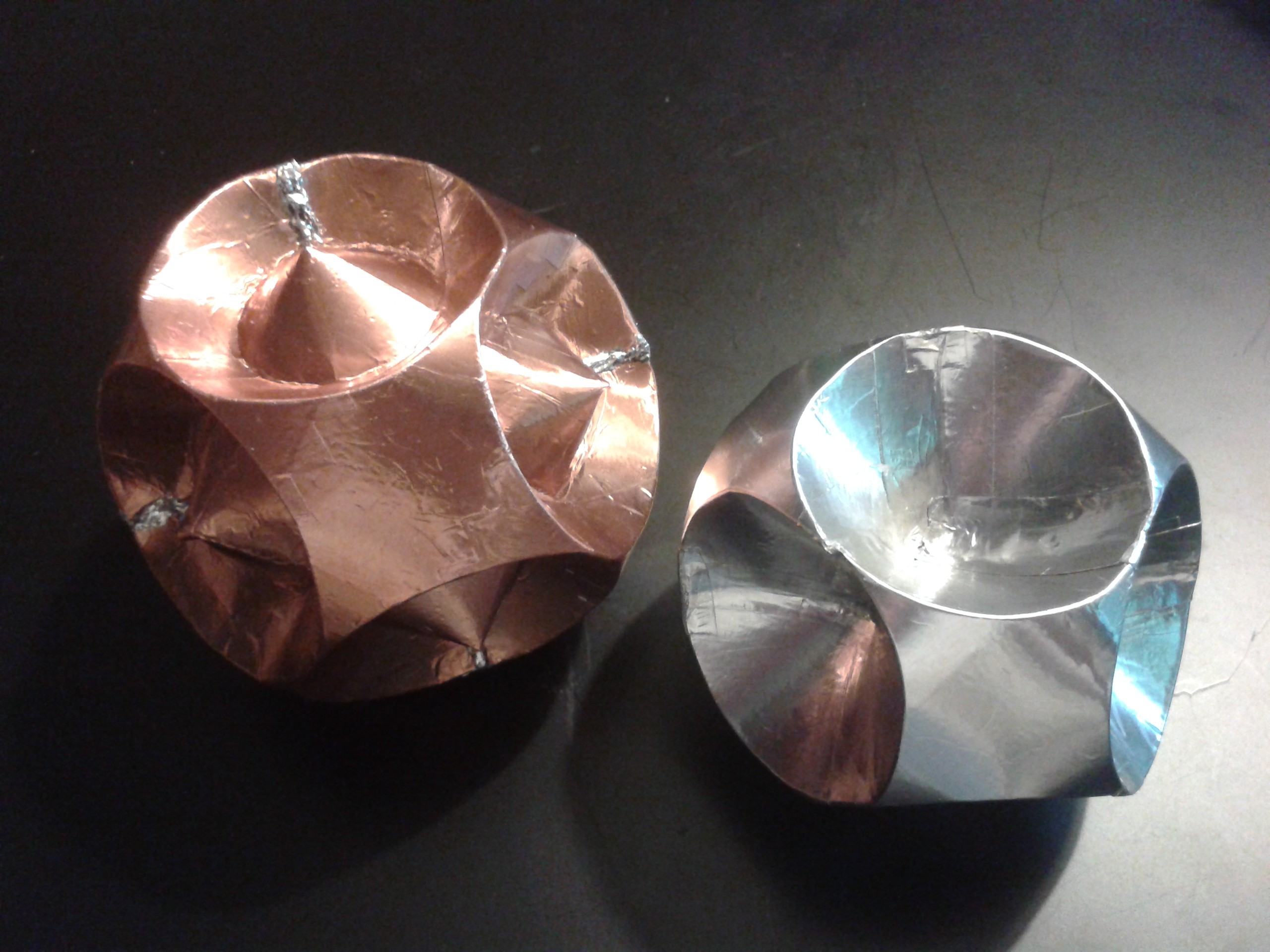
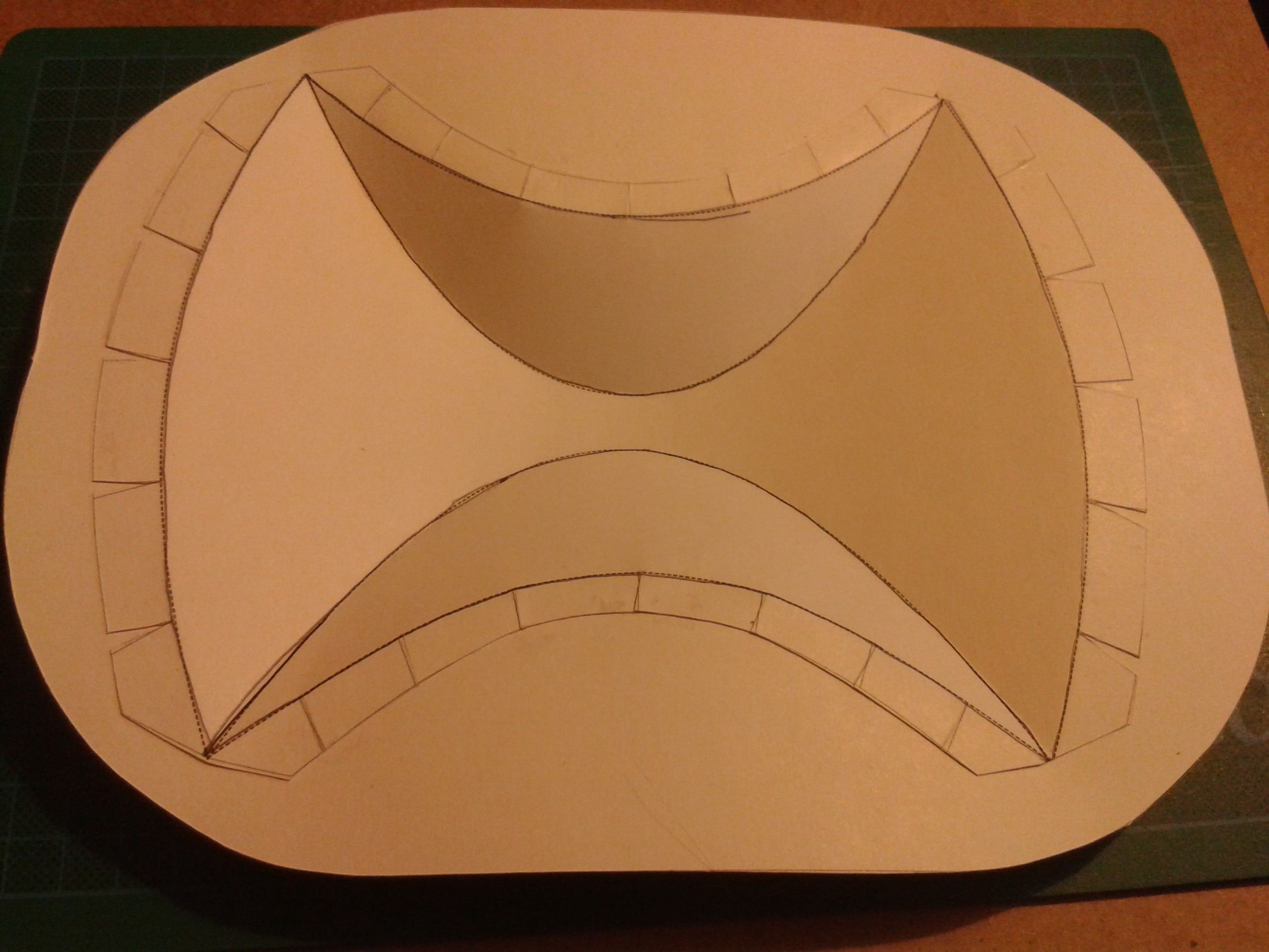
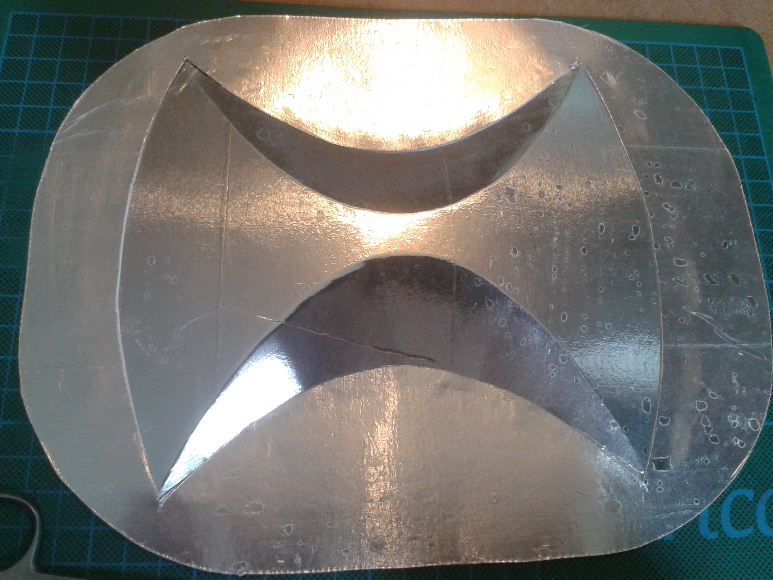
Like for example curving a single sheet of paper into a sphere with just one cut in it, and at least one fold.
Instead of folding the cube along the intersections, you can instead fold around them in a hyperbolic curve allowing extra-planar movement so that it forms a sphere (Sort of. With better resolution using more folds, this approaches a true sphere better.)
![]()
Interestingly a crucifix is one of these ancient mathematical proofs. I find it fascinating that the symbols we use to worship our gods are invariably universal proofs of something physical... It wasnt deliberate but this one happened to be cruciform.
![]()
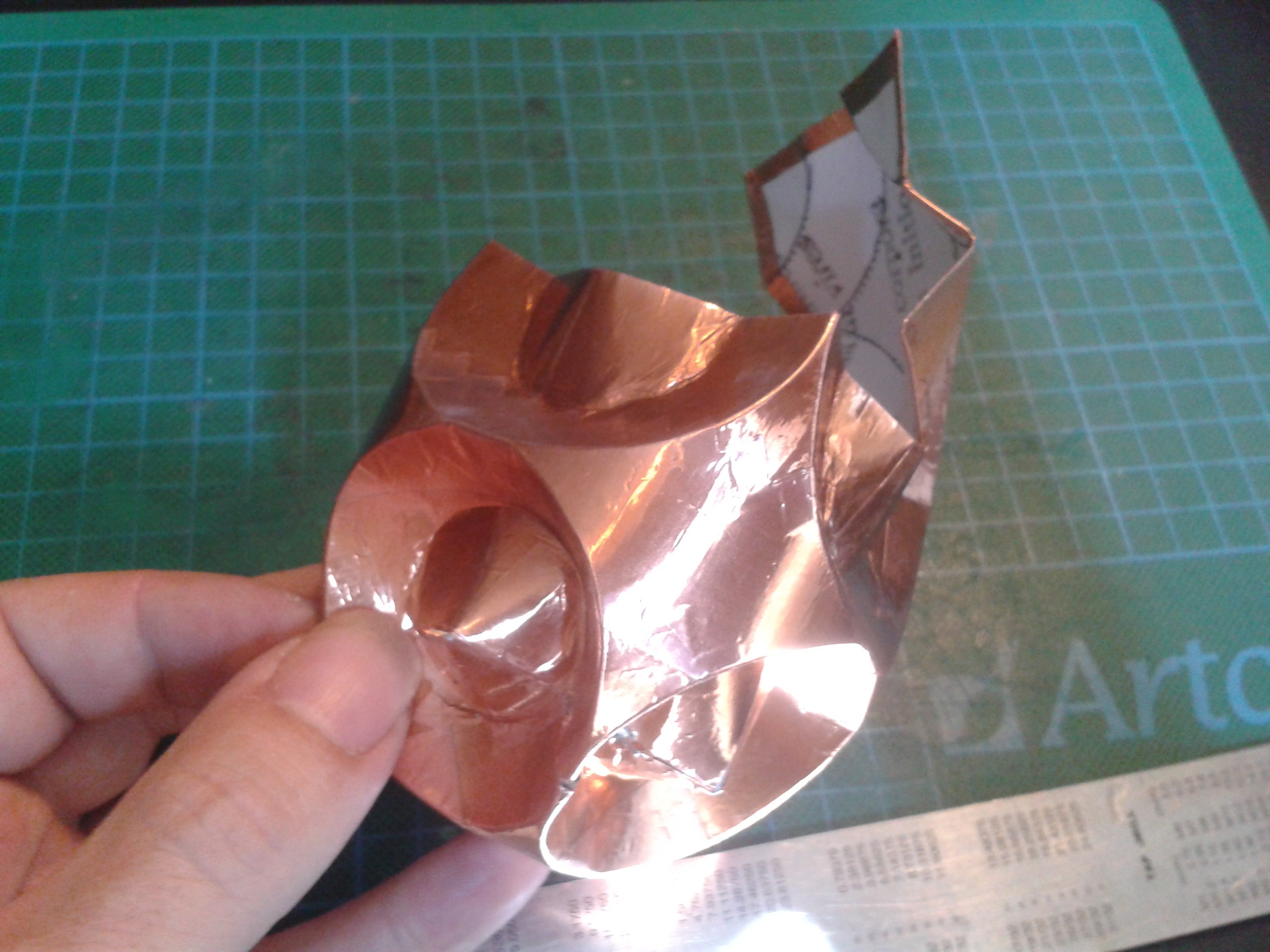
I've put copper tape on the surface of it before scoring and lapped the edges over so I can solder the seam into a solid object.![]() I dread to think what hatched out of here. You bring back stuff from other dimensions, its just asking for trouble ;-)
I dread to think what hatched out of here. You bring back stuff from other dimensions, its just asking for trouble ;-)One cut, one fold, one world.
![]() A single sheet of cardboard with a single simple perimeter cut formed into a ball with no overlaps, all the edges meet exactly.
A single sheet of cardboard with a single simple perimeter cut formed into a ball with no overlaps, all the edges meet exactly.
Morning Star
During the Holy Wars a little-known but much feared weapon arose. It consisted of a stave with a large metal ball on the end, armed with flanges or spikes in each quadrant. It got its name from the fact that carried upright by infantry and cavalry it looks like a star, but it is an ancient European design and the etymology is a translation from the Germanic Morgenstern, which was probably the family name of its designer. It's a form of Mace, and an ornamental sceptre usually carries one as a result. How this managed to get mixed up with Venus, which I am named for rather than this beastly device is a mystery but there you are.
Kind of in celebration of my new-found status, having clobbered my mortal enemies with typical thoroughness, I decided a bit of pomp was in order. Morning.Star needs something symbolic of it, so thats what I chose.
Morning Star's Metal Balls![]()
-
Some Outrageous Bending
08/19/2017 at 06:30 • 0 commentsSnake Hips again
![]()
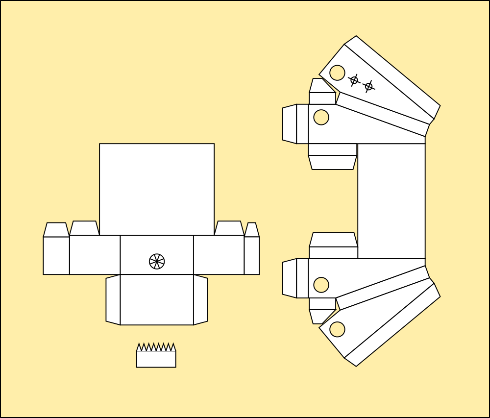
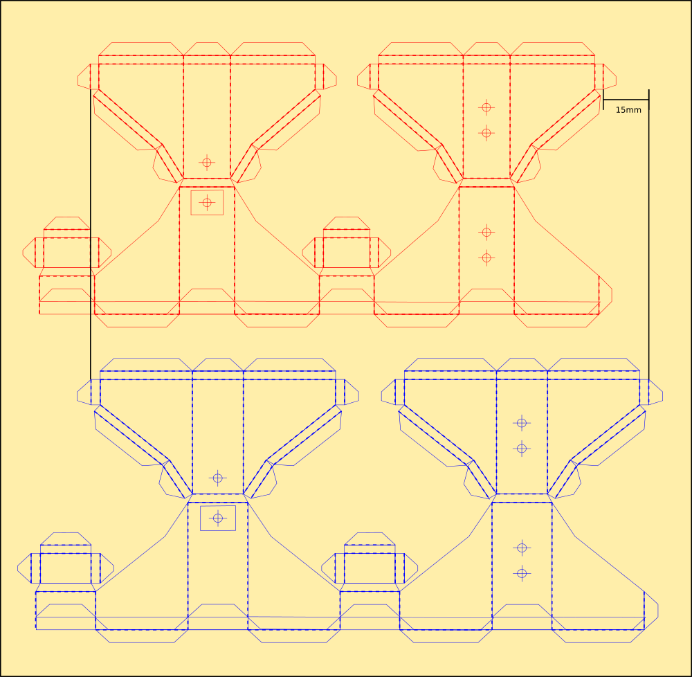
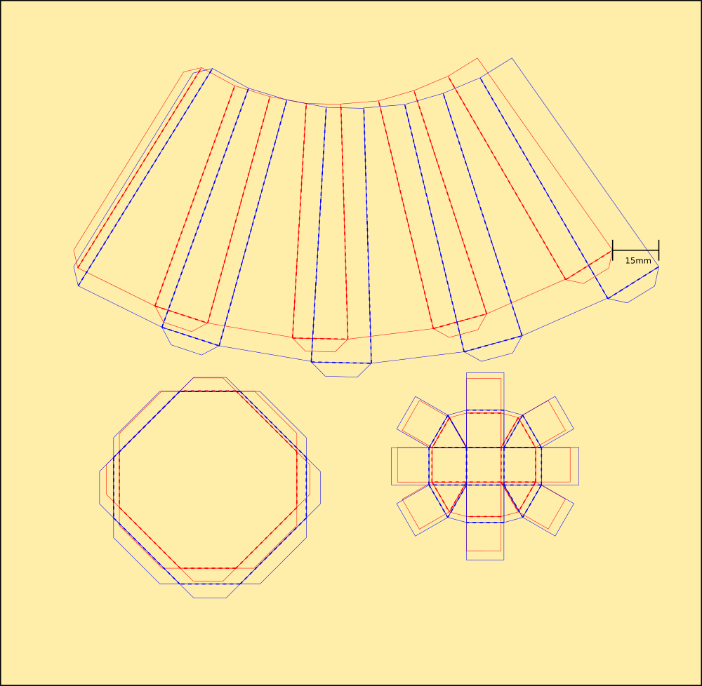
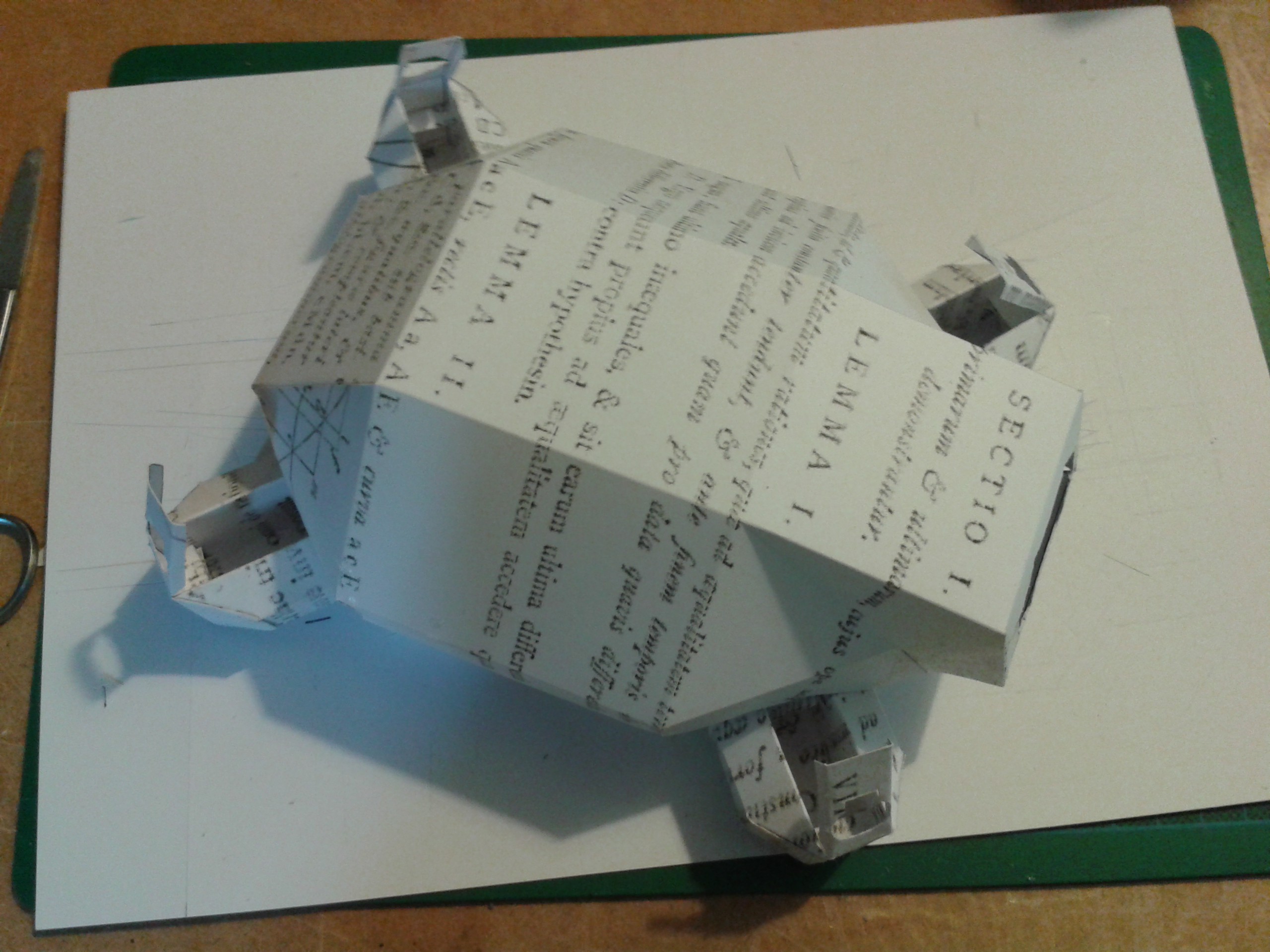
These should now be functional but still need joining to something. To give the system a bit of swagger I've decided to cant the hips out a little way to emulate human hip motion better. That familiar shape at the top of the femur is responsible for our toes turning out slightly and in again as we stride, bringing the foot under the body to balance on it keeps both moving in a straight line while your hips describe a zig-zag. We also flex our spines to accommodate it while keeping the shoulders still, but the extra weight will be too much for the ankle servos here so it wont have a torso.
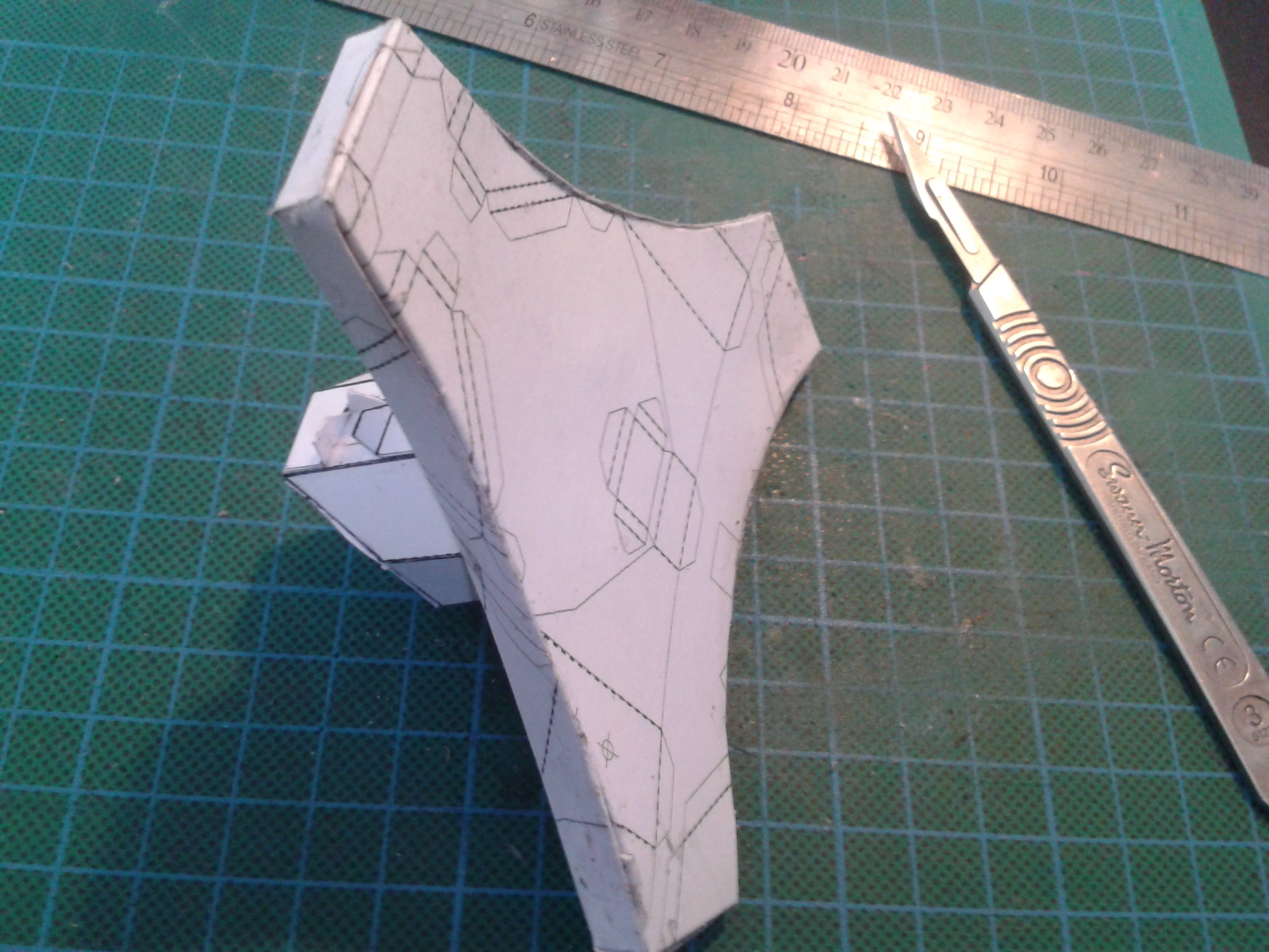
Nice Parabolics tho![]() To keep the weight down in the superstructure much of it is single layer. Those curves arent there for decoration although they do look beautiful. There isnt anything stronger than intersecting curved forms in plane surfaces - to get those hip angles would have required a lot of small polygons and still had floppy plane surfaces inbetween the stronger ridges formed by the mesh. That's completely rigid in comparison.
To keep the weight down in the superstructure much of it is single layer. Those curves arent there for decoration although they do look beautiful. There isnt anything stronger than intersecting curved forms in plane surfaces - to get those hip angles would have required a lot of small polygons and still had floppy plane surfaces inbetween the stronger ridges formed by the mesh. That's completely rigid in comparison.
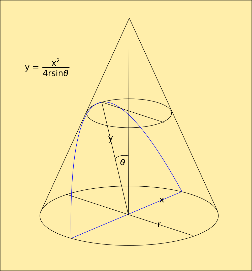
Proof that those are true parabolic surfaces; The top sheet would be warped unless it intersects the dome and crescent-shaped bites out of it on a mathematically straight line.Forging a chopper
![]()
You wish, Robin.
I had noticed the possibility of using these forms as moulds myself, and I will be experimenting on this when I have more time. Thermoplastics spring to mind as a good candidate, and I do have green sand and a helical forge that will melt aluminium. I've only got one set of tentacles though, and meantime they are engaged in trying to create a decent rotational bearing surface in cardboard.
Prototype Pelvis
![]() I've assembled the bearing from paper rolled around a rod and sealed with sticky-back plastic. another coated sheet went around that so the two fit together nicely and dont bind. The servos will turn the tops of these from the centre.
I've assembled the bearing from paper rolled around a rod and sealed with sticky-back plastic. another coated sheet went around that so the two fit together nicely and dont bind. The servos will turn the tops of these from the centre.
Servo mount and braceThis part just screws to the base and fits over the bearings as a module so it's all replaceable and just interfaces to the tops of the legs. This really would be a lot easier if it were a one-off but never mind.
![]()
The tops of the hip bearings will be cut down and plugged, then copper taped so I can solder plates to them to screw the servo actuators to.![]()
-
Codename Dirty Harry
08/15/2017 at 00:38 • 2 comments"I know what you're thinking. 'Did he fire six shots or only five'? Well to tell you the truth, in all this excitement, i kind of lost track myself. But being that this is a .44 Magnum, the most powerful handgun in the world, and would blow your head clean off, you've got to ask yourself one question: 'Do I feel lucky?' Well do ya, punk?"
Other than openly challenge the punk who's taken my work and claimed it his, along with the credit for the low-poly-count art movement in the UK design sphere - ludicrous peacock that he is - there isnt a lot I can do.
No wait, there's a lot I can do that he cant, because he's just a faker, not a maker.
Lets see if the punk can get up from a convex copper-jacketed surface like that of the slug fired by Harry's oversized weapon, shall we?
Retroactive Development
I'm pretty sure I've mentioned the concept of rolling back parallel development into Cardware and this is the result. Using the shielding from Decal and developing the geometry from Internet of condoms, I've revised the system completely.
![]() To get the top and bottom surfaces of the foot to curve in two planes at once takes a bit of work. Putting a curved crease in a sheet stresses the material along its surface plane, stiffening it considerably, and also alters the orthogonal outline of the shape. Figuring out the dimensions for the mating surface underneath has to be done mathematically.
To get the top and bottom surfaces of the foot to curve in two planes at once takes a bit of work. Putting a curved crease in a sheet stresses the material along its surface plane, stiffening it considerably, and also alters the orthogonal outline of the shape. Figuring out the dimensions for the mating surface underneath has to be done mathematically.
![]()
Thankfully, the maths for this is actually really simple, they are just Parabola. Same as the trajectory of a bullet. Not that it matters at this range.Boom, headshot
![]()
Did you follow that, Robin? Doubt it. You think Network Node Analysis is geometry. It isnt - LPC Art relies on statistical analysis of the nodes and their interconnects and doesnt require knowledge of the angles between them. You'd know this if you'd actually used the two entirely different types of mesh generated by the techniques.
A bit of heat, and you sag like your poncy perfumed candles.
I'm still not done. I've integrated Decal's laminar technology, adding structural integrity, EM shielding and a really nice aesthetic to it.
![]()
There's 3 layers to that, cardboard, copper and sticky-back plastic. I dont know what that is made of but it just vanishes without much in the way of smoke or residue and solders clean through with no trouble.
![]()
The only consideration with this technique is lapping the edges of the copper over the edge of the cardboard, because solder really doesnt like bridging these gaps. Unlike copper plate, it solders with a 15W iron because the copper is too thin to wick the heat away. It bends and curves like copper too, but cuts with a scalpel or scissors, can be glued and printed on and doesnt scuff or pick up fingerprints with the plastic coating.
Gold standard in modelling materials
![]()
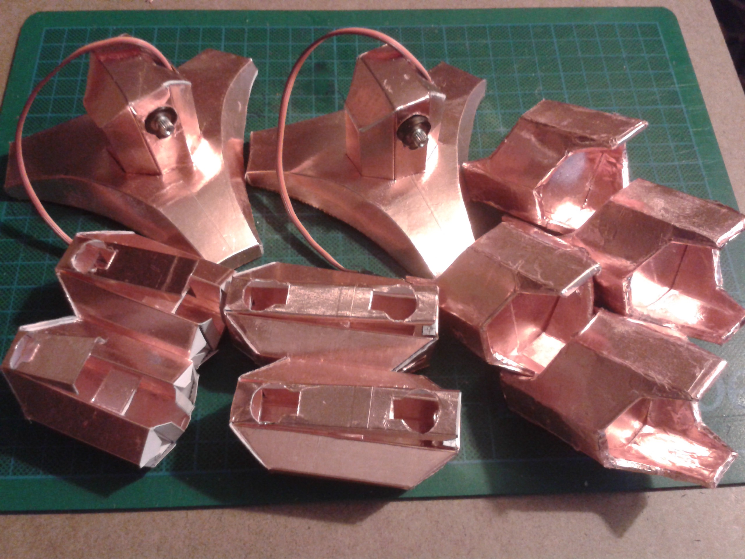
I've treated all the parts in similar fashion. Hard to believe that's cardboard and weighs almost nothing.
![]()
New sensors
Because Cardware weighs so little I had too much trouble using the QTC I'd planned. An entire leg barely registers, and because of the way it is manufactured each piece behaves slightly differently so it's hard to calibrate too.
Instead, I've added potentiometers to the joints and am using angular displacement to sense the robot's true position against the intended one. I had to use the micro potentiometers and modify them as well to get them to fit in the joint, but the bonus is they have replaced the hinge mechanism too.
I first used the plastic capped type and drove a screw into it to affix them but they turned out to be really weak and broke in minutes.
I've gone over to the metal-chassis type and modified the legs and wiper.![]()
![]()
![]()
That now fits neatly into the gap between the powered and unpowered modules opposite the servo actuator.
![]()
Rejigging
After all the little bits of adjusting I'd done to each part I had to go back over the entire set to make sure they still fit together perfectly and behave as a system. This wasnt easy because the parts are universal; change one, you change all to match.
Finally I got them all to tessellate together. This is missing the radial servo from the top that rotates the entire limb so the robot can turn corners without shuffling, but otherwise displays the 5DOF - 180 degree throw on every plane I've been working towards.![]()
-
Superstition II
05/09/2017 at 14:46 • 0 commentsWell I've spent the last two out of three days laid up on the sofa shaking and sweating after being possessed by the most outrageous Flu. I'm feeling a bit better today thankfully, and I can work without dripping on the cardboard. Lovely...
I was also really peeved to find out that the servos I ordered are a completely different size to the others. I carefully collected a range of servos and measured them all after discovering that the standard needed standardising. I really hate this behaviour - standards are what they are for a reason, either stick to them or abandon them because anything else is a mockery.
Metal Gear servos (at least, these ones) are a good 5mm taller above the mounting points than all the plastic ones. The motor shaft is physically longer, and the black nylon actuators supplied with each are also much heavier. The motor box is also a lot longer than the biggest plastics too.
![]()
There was absolutely no need for this, the hardware is identical but for size. I can understand what Futuba did to the standards for heavier servos, but that crud is just irritating. There's 5mm of dead space in the bottom the motor box, all it would have taken was to move the bearer points up so that they were the same.
Hobby Servo motors are rubbish and have been around as long as i have. They have not changed in all that time. Considering I've been using them with MCU's as part of powered hinges like everyone else for a decade, why have they not been redesigned as hinges?
@Dylan C. is working on a design like this so that we can interface them to something other than Wright Bros technology.
![]()
Its probably going to be 3D printed, but I have been working on ways of getting around a lack of such technology. Origaime is a harsh mistress :
![]()
Cut and scored from Polyethylene, this is repeatable and sort of works.
Other modifications were needed for the bigger servos. I discovered that they no longer fit between the cheeks of the saddle units, although I had allowed enough depth in the thigh sections for them to fit. This meant completely rescaling the limbs, which I have now done. One of the reasons for designing the limb parts this way is scalability. Because the new servos are 5mm longer, the saddle template would have to be 15mm longer around it's perimeter. Because of the unitary nature, all the sub-dimensions are related to the overall scale:
![]()
The same procedure is applied to anything that part interfaces with. The lower limb shell needed stretching to match the new saddle, I just scaled the entire thing including the foot and internal brace.
![]()
I chose a new design for the skin of the fully operational shell. Form and function still ringing in my brain, I decided that the original text from Newton's Principia - The Motion of Bodies seemed particularly appropriate.
The apple never falls far from the tree
![]()
And just like another famous apple, this one also stands on the shoulders of giants. The only difference is, I'm making a point of it, and not a fortune. There's a big difference between artistic license and outright theft of IP. Coincidentally those two letters precede everything they've done.
Take a hike hosers. I've been doing this for years.
![]()
-
Superstition
05/06/2017 at 12:16 • 0 comments![]()
Cardware
An educational system designed to bring AI and complex robotics into the home and school on a budget.
 Morning.Star




 I had an awful lot of trouble with these too. After splitting the harvested ones I first tried by driving a screw into them, I bought some 'quality' ones and glued them to a bearer.
 Unfortunately the glue capillaried up one of the channels and got on the track or wiper and locked most of them solid. Only a couple worked and those I freed off read open circuit.
 Not that it made any difference really, they were advertised as 5% tolerance. Somebody couldnt count and I was pretty sure it wasnt me. They were all pretty bad except for one, which measured 99.7K. I suppose that constituted the 5% out of the batch that could be called within tolerance. Hmmm... This isnt what I call quality, those are K's its out by. Errors in hundreds of Ohms I can understand, but as a voltage divider that is utterly useless.
 I shopped around a bit. The one on the left looked promising until I discovered sneakily soldering those tabs to the wiper plate and then to a plate left specks of flux all over the track so it had dropouts in it. I couldnt clean them up and all but gave up.
 While I was looking online I discovered a previously unknown description for them. I'd tried potentiometers, variable resistors, trimmers but hadnt thought of Presets. Thats what these are apparently. And Squires had them in stock, so I got them local too.
 At last something solid that I can keep glue out of and find an interface for! I shaved off the bezels so they would lay flat on the cardboard and covered the backs with metal tape before turning to my favourite metal of all to build something to turn them with. Something that I could also secure to a flat surface.
 The copper pin didnt fit the slot quite right and there was a little bit of play so I fitted it across the arrow instead. That worked a treat until I got to number 4 and discovered the remaining half werent completely identical. There's two different types of arrow... Nice one, Iskra. I dont know which is the old spec, but I think it may have something to do with the one on the right being impossible to read without magnification let alone in a dark recess lit by the backs of LEDs. I just hope thats the old one. A bit of filing sorted it out anyway...
 And it fits even better than all the trimmers, some of which worked out over 6mm high with the circuit board to mount them. These are under 5mm high.
 A bit of wiring later...
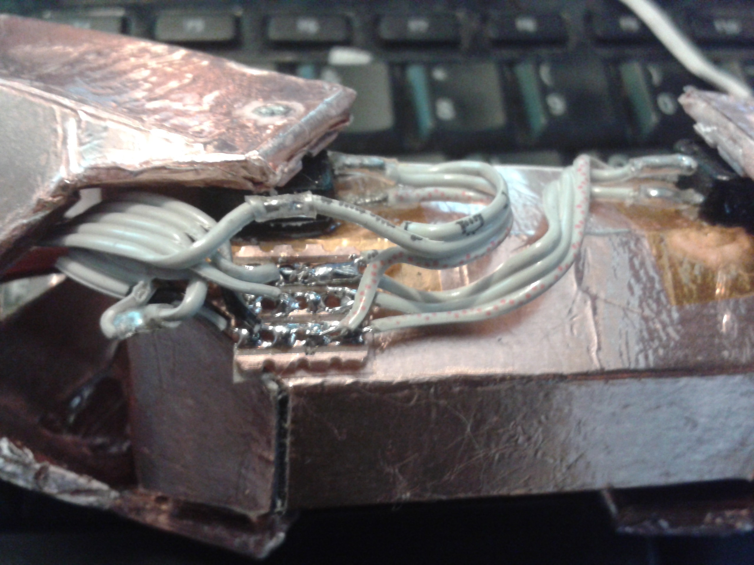 Thats got the limbs reassembled with working angular sensors, and without having to take apart a brand new set of servos. I may have a go at hacking these at some point after reading Radomir's
  I also had some servo trouble at the top end and had to redesign the interface to the tops of the limbs. They were driven directly by the servo shaft, but limitations with the materials and the rather ancient design of the mountings meant I had to fall back to the barbaric practise of chassis-mounts and push-rods. Every time I see that mechanism, I also see flapping canvas and flying-ace goggles spattered with engine oil, followed by a plume of smoke. :-D
 The bearings are made from 'paper metal', which has turned out to be another interesting and useful hybrid of materials. The rods for the thigh pieces are made by wrapping a sheet of paper around a metal rod and securing the end with a piece of metal tape several layers deep. It is burnished with a piece of dowel before being wrapped with another piece of metal tape glue-outwards. Finally this is wrapped in a sheet of paper and secured with more tape. The resulting bearing and shaft set weighs very little, is as strong as plastic, fits perfectly and can be greased to further extend the life of the working surfaces, which are all-metal.
 All I have to do now is trim that up, plug the tops of the tubes with something I can screw a lever to, and then mount the servos as per a model aircraft. Shudder...




 I dread to think what hatched out of here. You bring back stuff from other dimensions, its just asking for trouble ;-)
 A single sheet of cardboard with a single simple perimeter cut formed into a ball with no overlaps, all the edges meet exactly.
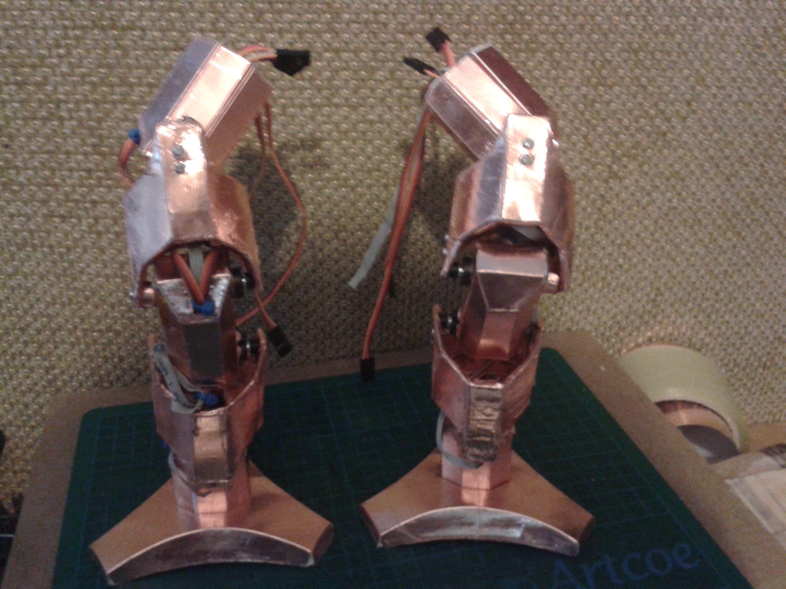
 To keep the weight down in the superstructure much of it is single layer. Those curves arent there for decoration although they do look beautiful. There isnt anything stronger than intersecting curved forms in plane surfaces - to get those hip angles would have required a lot of small polygons and still had floppy plane surfaces inbetween the stronger ridges formed by the mesh. That's completely rigid in comparison.
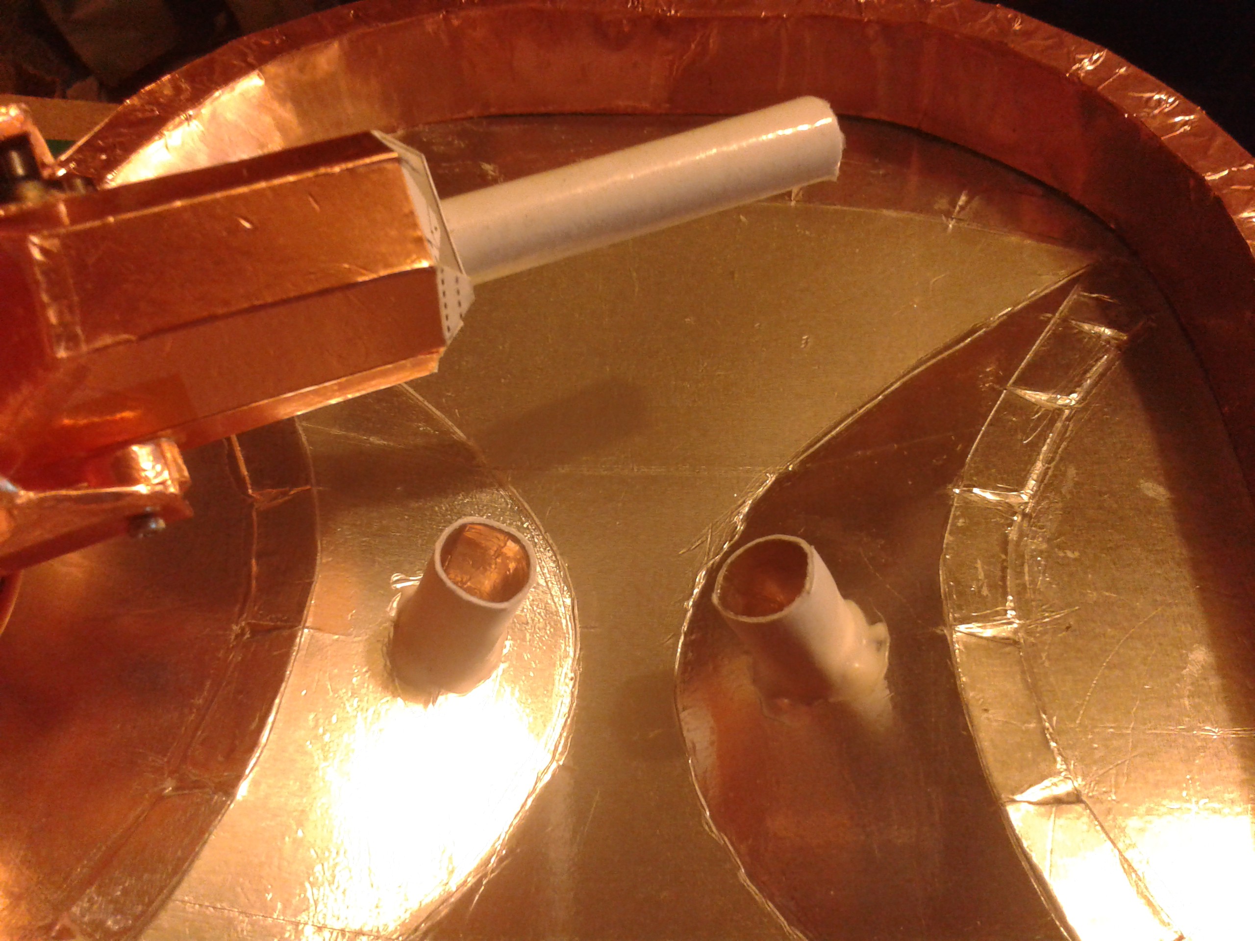 I've assembled the bearing from paper rolled around a rod and sealed with sticky-back plastic. another coated sheet went around that so the two fit together nicely and dont bind. The servos will turn the tops of these from the centre.
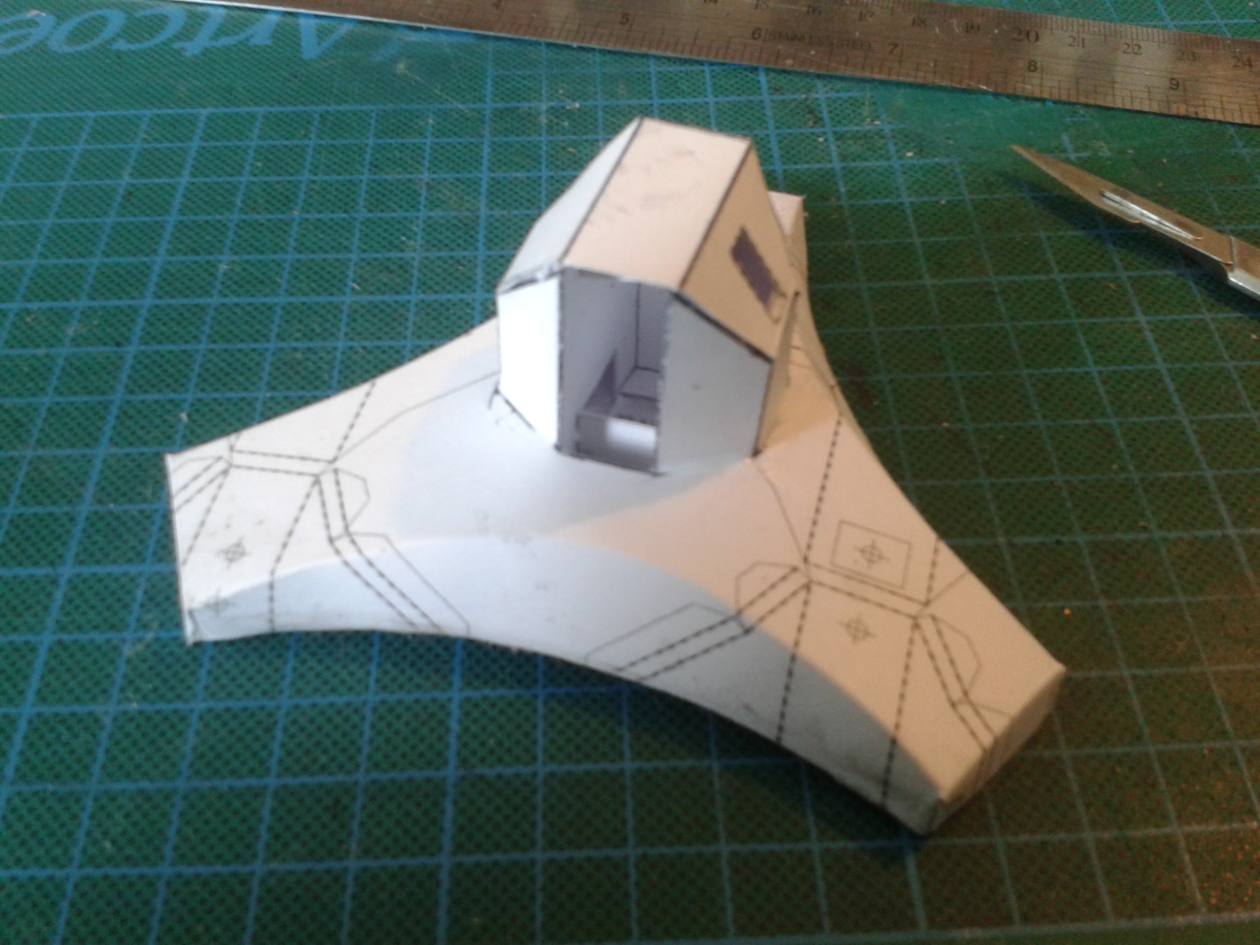 To get the top and bottom surfaces of the foot to curve in two planes at once takes a bit of work. Putting a curved crease in a sheet stresses the material along its surface plane, stiffening it considerably, and also alters the orthogonal outline of the shape. Figuring out the dimensions for the mating surface underneath has to be done mathematically.