-
1Step 1
Disassemble the disc, remove and keep internal components.
The top half has the C ring, the bottom half has the battery door.
Trim the 6 wedges from inside the soft plastic ring - be careful to not damage the lip on the inner edge that holds the ring in place.
-
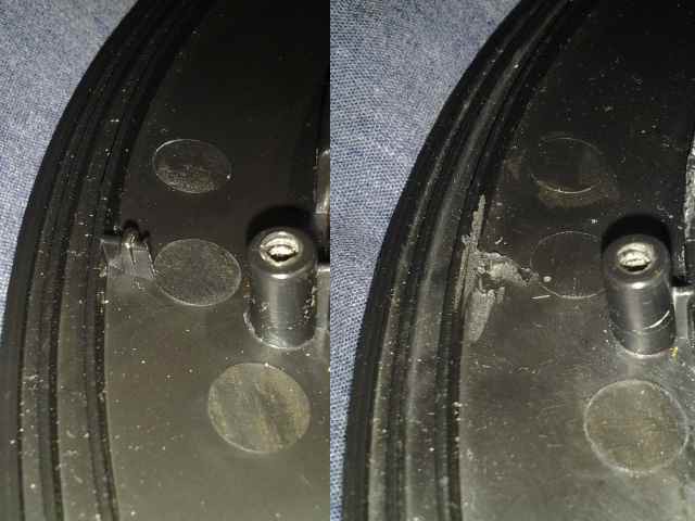
2Step 2
Make room for the outer LED ring on the top half of the disc:
Completely trim away the 6 short spurs (by the screw posts)
![]()
-
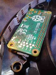
3Step 3
On the bottom half of the disc, make room for the RPI and outer LED ring:
The battery will be placed in the largest open area.
For the RPI: trim down the post and screw mount where the bump sensor was.![]()
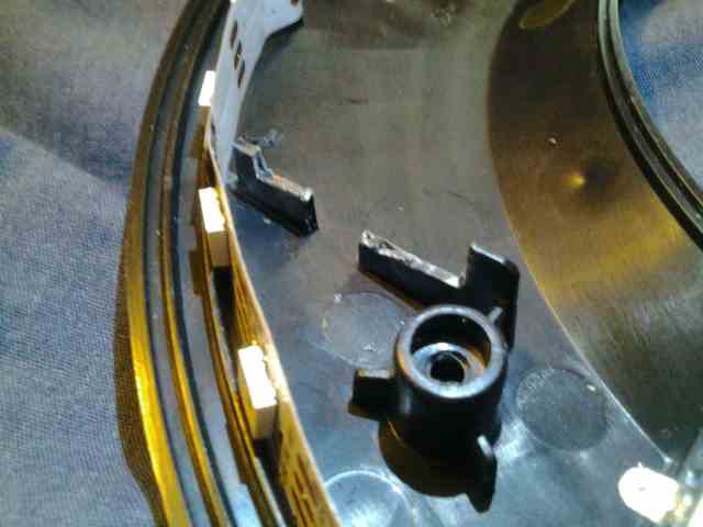
Cut a notch for the LED strip to go around the outside of the RPI.
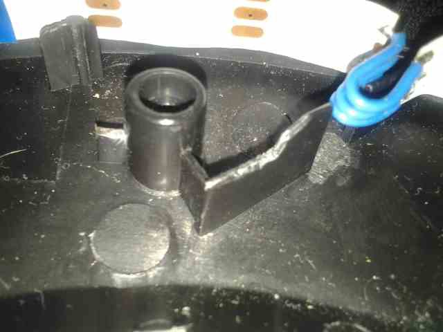
To help the RPI fit under the C ring: cut a few mm down into one rib.![]()
At the other end of the RPI, similarly trim down one rib of the screw support.
Also trim down the inner side of the 4 ribs that stick up, to give the C ring more room.![]()
-
4Step 4
Choose to either:
A: (more cutting) cut a notch out of the outer edge of the remaining 4 rib obstacles blocking the LED ring
or
B: (more soldering) cut and extend the LED strip to bend around and go through the existing slots the ribs. -
5Step 5
Remove any double sided tape from the LED strip.
Add a small capacitor directly to the back of the LED strip. This will help to filter noise from getting in/out of the LED power circuit, and prevent the LEDs from acting erratically.
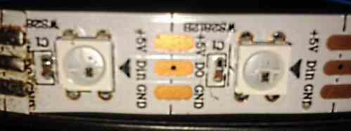
When cutting the LED strip:
If your LED strip only has one via (the small hole) on the data signal (the middle trace):
On the half with the via, the signal is available on the front and back (the half without the via must connect from the front).
Do not cut through the via - that may damage it.If you cut one end too short, gently scrape the paint to uncover more copper.
![]()
-
6Step 6
Carefully cut out the old battery area to get more room for wiring and components. Leave the nut, walls matching the battery door, and some corners for the outer edge (so the door won't fall through).
If you don't need the whole battery area space, you may get by with only removing the spur from the outside middle of the battery area.
-
7Step 7
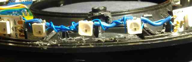
Add LEDs in the battery door area: The lip around the battery door will prevent a simple continuation of the strip.
De-solder 3 LEDs from unused LED strip (or buy separete LEDs)
Connect the LEDs to the main LED strip with one solid wire (for structure) and wire wrap wires.
Complete the loop with power and ground
Chain DOut to Din, but leave the last added DOut disconnected.![]()
-
8Step 8
Install Raspbian Lite on the SD card
Connect USB to serial device between PC & the RPI serial port (for debugging)
Setup as a USB Ethernet Gadget (to install software packages, drivers and updates)
http://blog.gbaman.info/?p=791
If using Windows 10, you probably need to manually change the driver to Remote NDIS device.
Setup internet connection sharing, or static IP and route. -
9Step 9
Audio through the PAM8302A is working without a filter (capacitor & resistor) -- but adding a filter may reduce CPU noise on the output.
Audio / Text to speech options:
- espeak
- festival festival-english
- flite
- libttspico-utils (writes to wav file, not direct to audio device)
Problems: RPI cannot split the PWM channels, cannot limit audio to a single channel
Enable audio in /boot/config.txt
Add audremap overlay to output audio on pins BCM12 & 13
#----Set volume to 100%
#--display the channel name eg. 'PCM'
amixer scontrols
#--set channel volume
amixer sset 'PCM' 100% -
10Step 10
LED options:
- rpi_ws281X DMA https://github.com/jgarff/rpi_ws281X
- SPI with DMA?
36 WS2812b LEDs will take about 1.7 amp at full bright white. Originally planned to boost to 5V, but then the current draw goes above the 2A limit of the battery protection circuit (which would only run LEDs at half brightness...) (could increase the limit, but the inefficency of the boost would decrease runtime)
Boost is not required: WS2812b and RPI both work with less than 5V
- Green & Blue LEDs need higher voltage then red (3.0 - 3.4 vs 2.0 - 2.2)
they may not reach full brightness at low battery, depending on battery/wiring/temperature/etc. - RPI could become unstable at low voltage - a small boost for just the RPI is an option
Tron Identity Disc upgrade.1
Upgrade a Tron Identity Disc with: RPI Zero, WS2812b LEDs, Sound, Gyro/Accel, USB storage/networking/charging, Wi-Fi, haptic feedback...
Discussions
Become a Hackaday.io Member
Create an account to leave a comment. Already have an account? Log In.