-
1Circuit Assembly Process
![]()
![]()
![]()
![]()
![]()
![]()
![]()
![]()
![]()
![]()
![]()
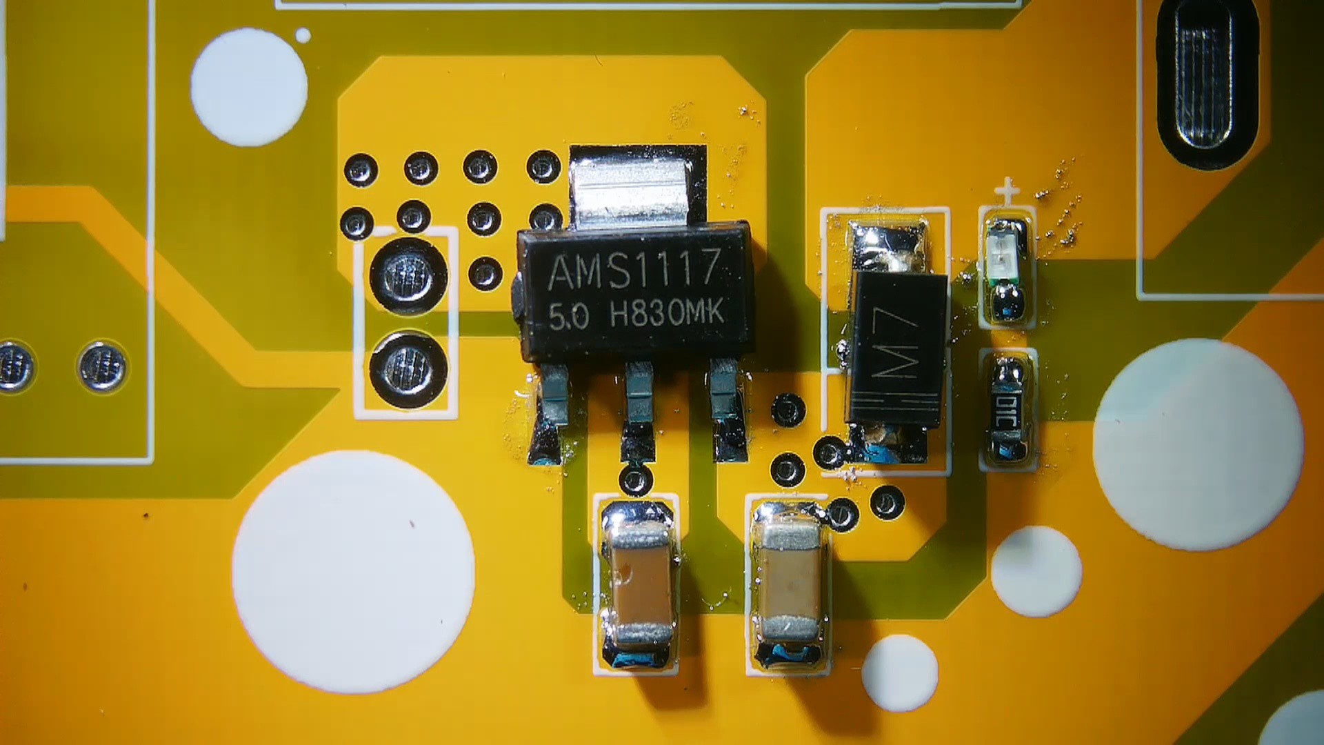
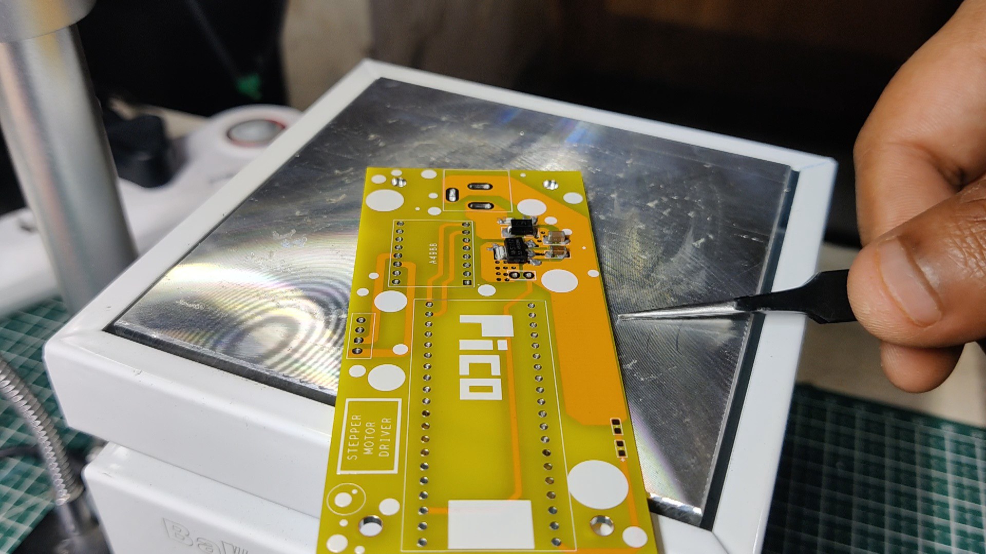
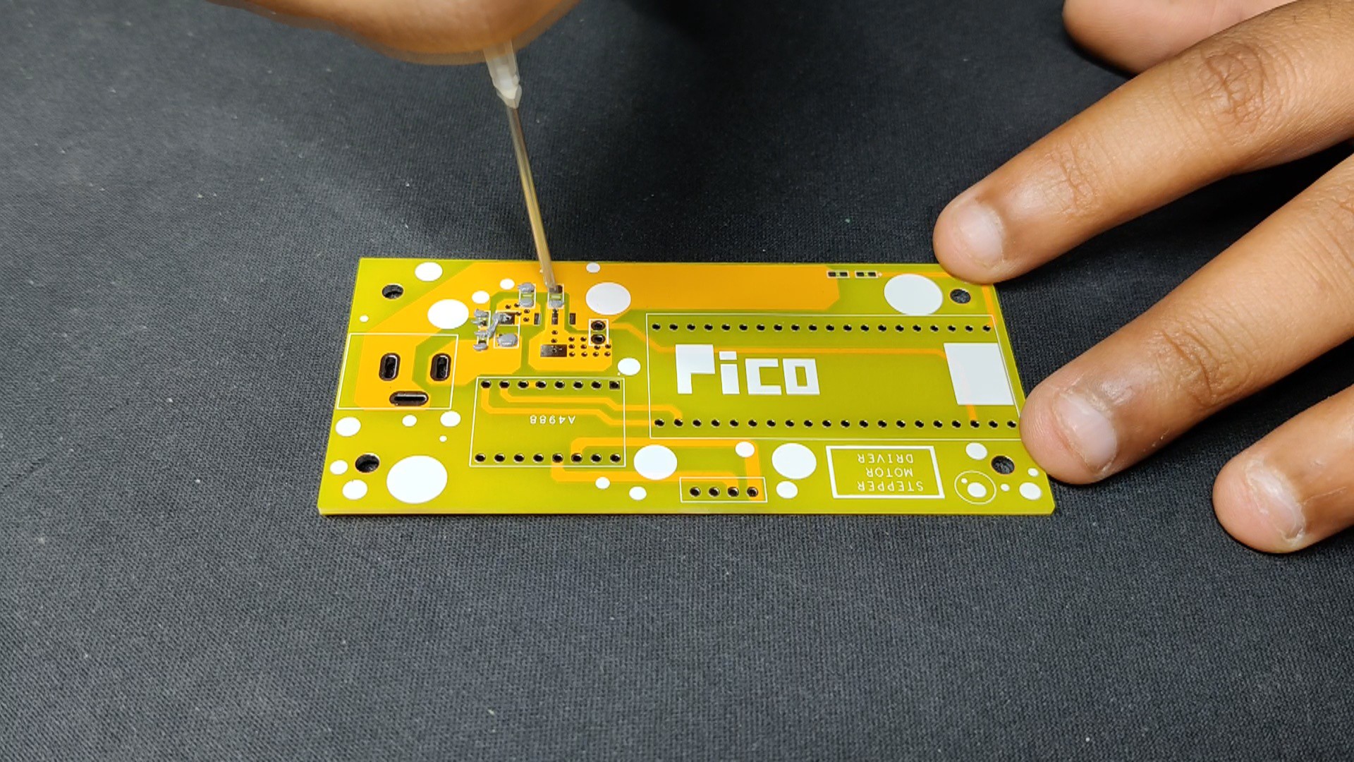
- We begin the circuit-built procedure by utilizing a solder paste dispensing syringe to add solder paste to each pad of the SMD components. In this instance, the 63/37 Sn/Pb Solder paste, which melts at the temperature of 190° Celsius, is being used.
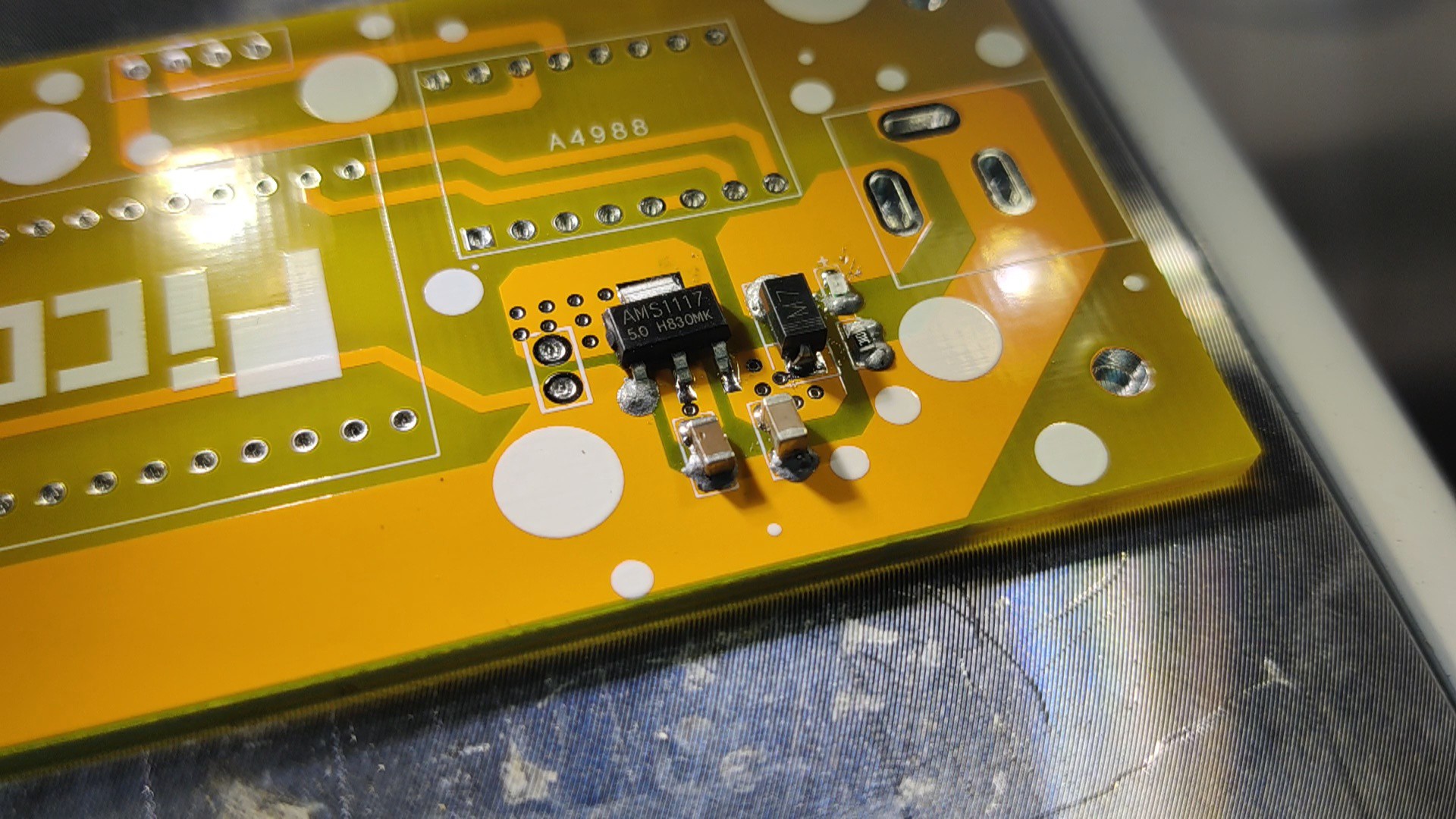
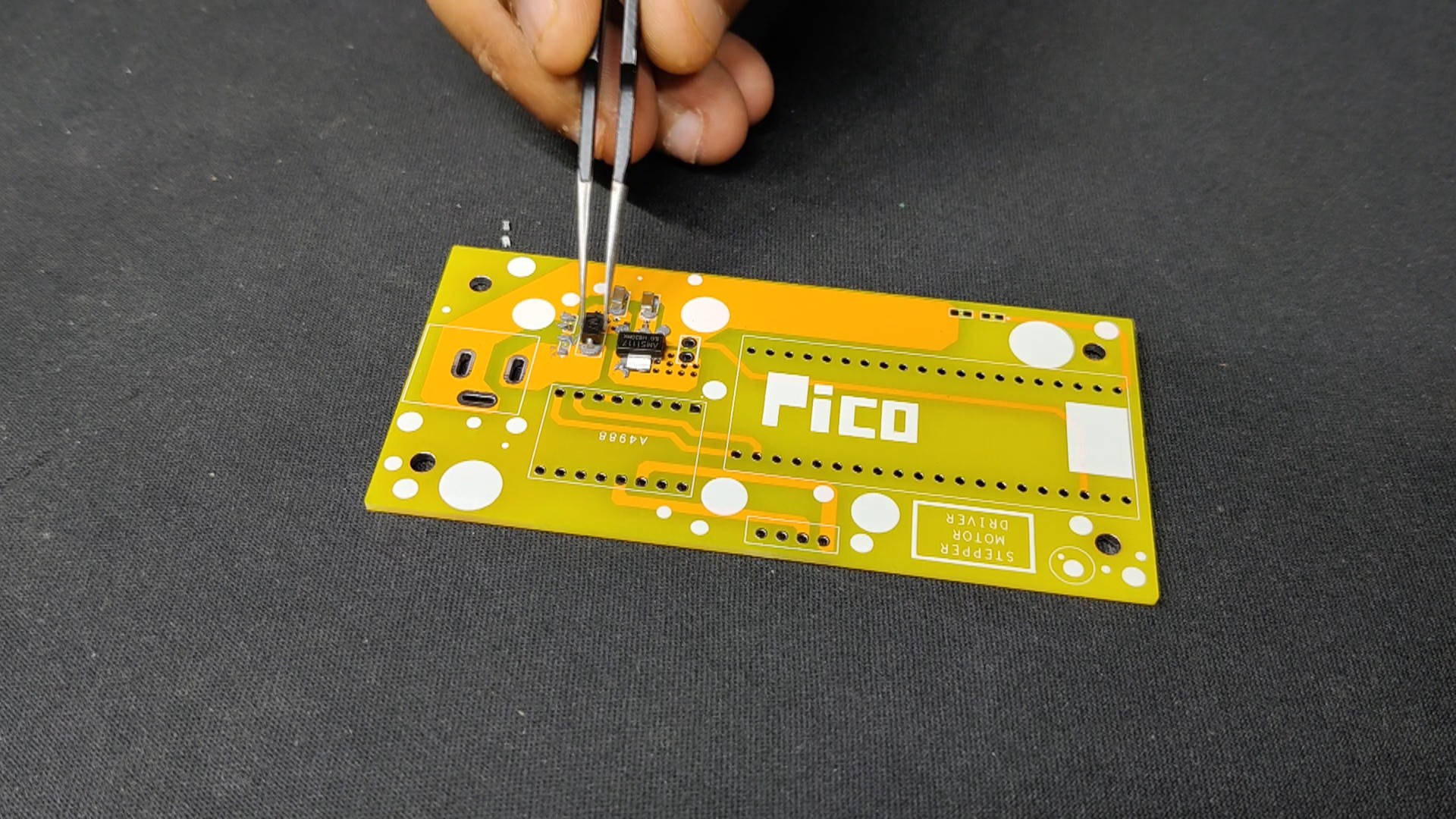
- We next pick and place each SMD component in its proper location using an ESD Tweezer.
- All SMD components are then permanently soldered to their pads when the entire circuit board is placed on the reflow hotplate, which heats the solder paste to its melting point.
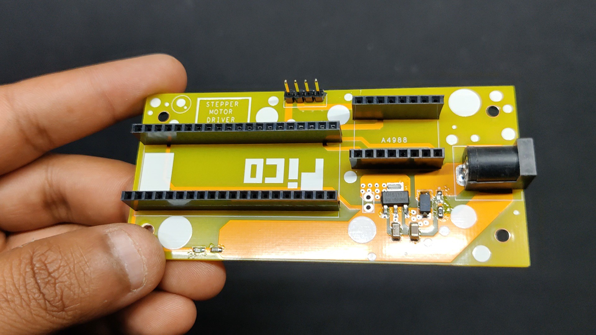
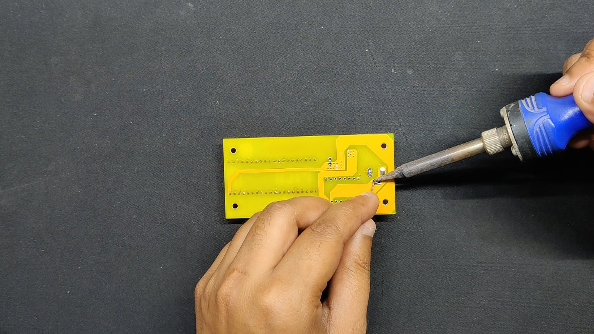
- The THT components, such as the male header pin, female header pin connectors, and DC barrel jack, are then positioned in their proper positions, and their pads are soldered with a soldering iron.
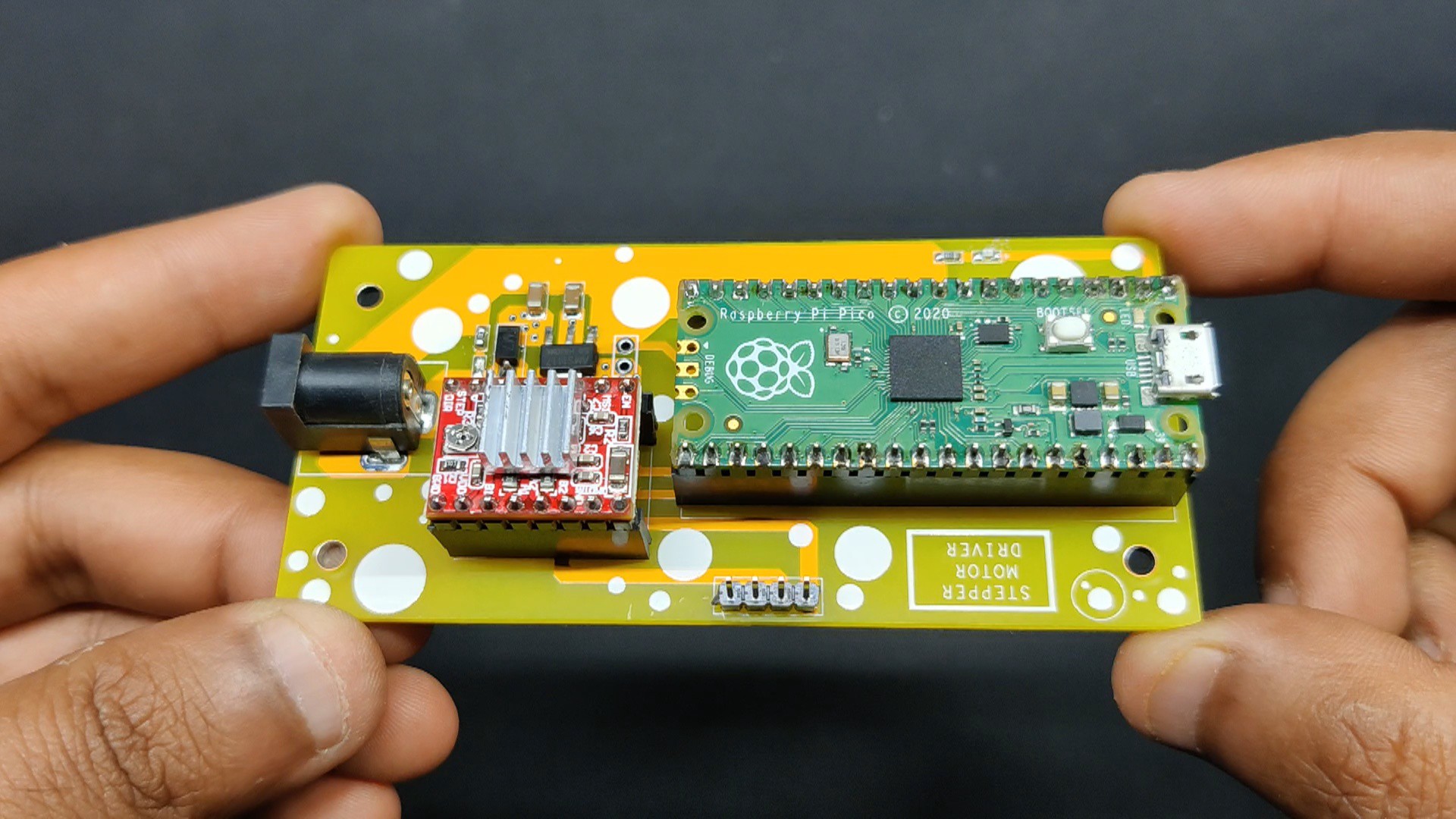
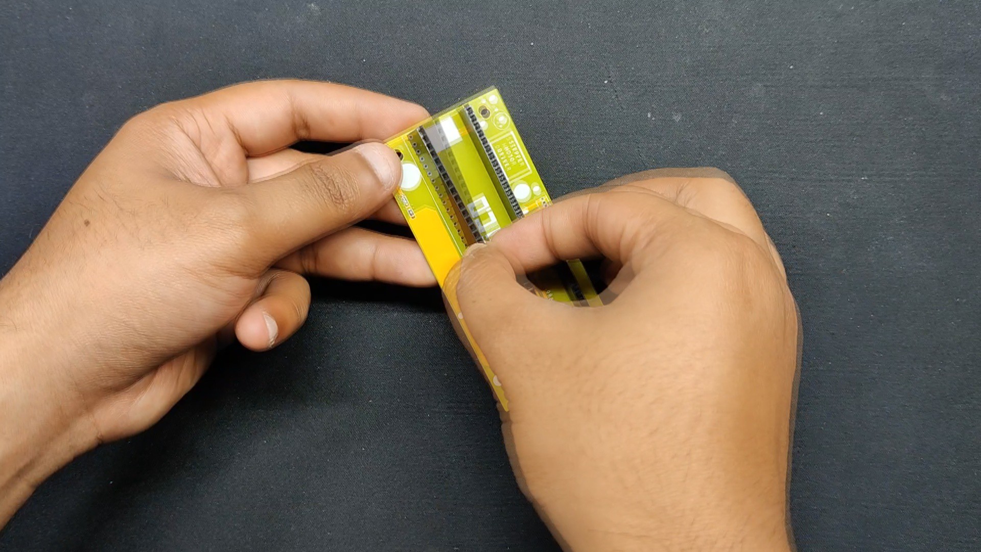
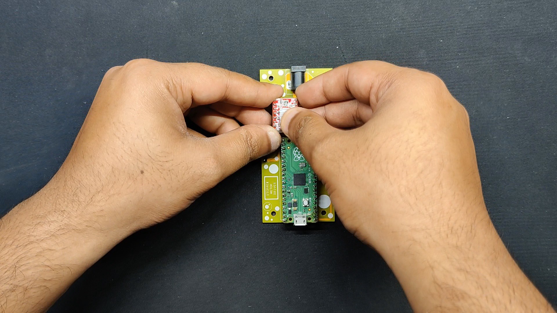
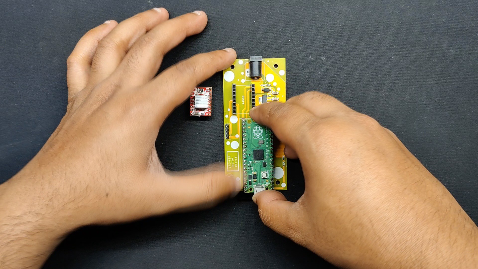
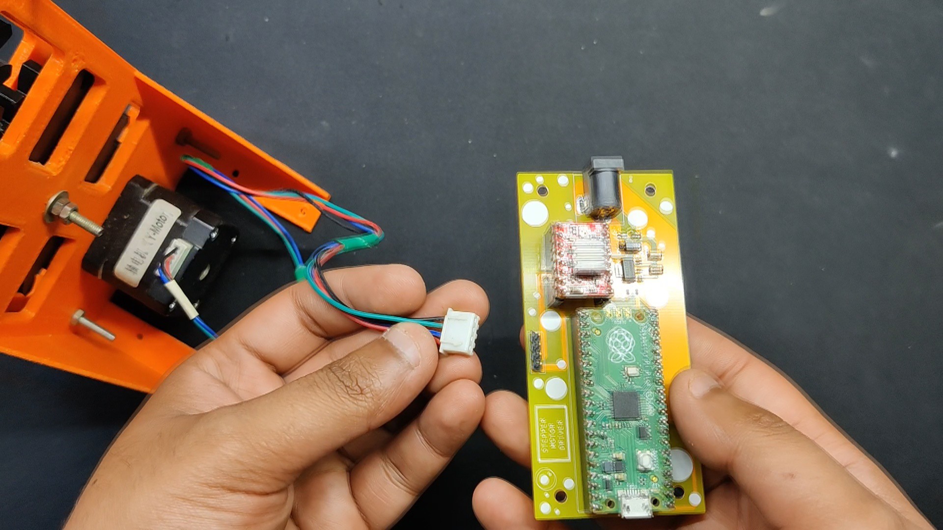
- After that, we position the A4988 Motor driver in its proper location and place the Raspberry Pi Pico on the female header pins.
Circuit assembly is now complete.
-
2CODE
We next uploaded the below sketch into our Raspberry Pi Pico.
const int dirPin = 16;
const int stepPin = 17;
const int ledPin = 0; // Pin connected to the LED
const int stepsPerRevolution = 200;
const int maxSpeed = 1000; // Maximum speed in microseconds
const int minSpeed = 2000; // Minimum speed in microseconds
void setup()
{
// Declare pins as Outputs
pinMode(stepPin, OUTPUT);
pinMode(dirPin, OUTPUT);
pinMode(ledPin, OUTPUT);
}
void loop()
{
// Blinking LED when motor is moving
digitalWrite(ledPin, HIGH);
// Set motor direction clockwise
digitalWrite(dirPin, HIGH);
// Ramp up speed from low to high over 5 seconds
for (int speed = minSpeed; speed >= maxSpeed; speed -= 20)
{
for (int x = 0; x < stepsPerRevolution; x++)
{
digitalWrite(stepPin, HIGH);
delayMicroseconds(speed);
digitalWrite(stepPin, LOW);
delayMicroseconds(speed);
}
delay(50); // Small delay to avoid skipping steps
}
delay(2000); // Hold at max speed for 2 seconds
// Set motor direction counterclockwise
digitalWrite(dirPin, LOW);
// Ramp up speed from low to high over 5 seconds
for (int speed = minSpeed; speed >= maxSpeed; speed -= 20)
{
for (int x = 0; x < stepsPerRevolution; x++)
{
digitalWrite(stepPin, HIGH);
delayMicroseconds(speed);
digitalWrite(stepPin, LOW);
delayMicroseconds(speed);
}
delay(50); // Small delay to avoid skipping steps
}
delay(2000); // Hold at max speed for 2 seconds
// Turn off LED when motor stops
digitalWrite(ledPin, LOW);
delay(1000); // Optional delay between cycles
}
This is a simple sketch that we created that does not require any libraries to function. The stepper motor and an LED are essentially controlled by this code, which causes the motor to accelerate in both directions and blink the LED when the motor is running.
-
3STEPPER MOTOR SETUP
![]()
![]()
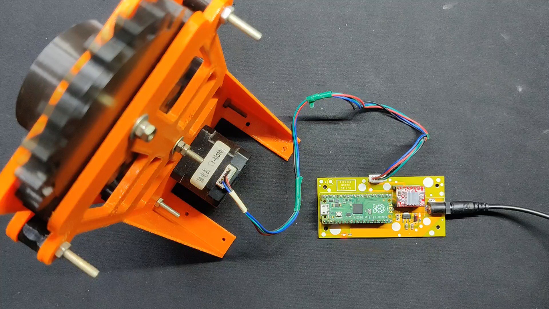
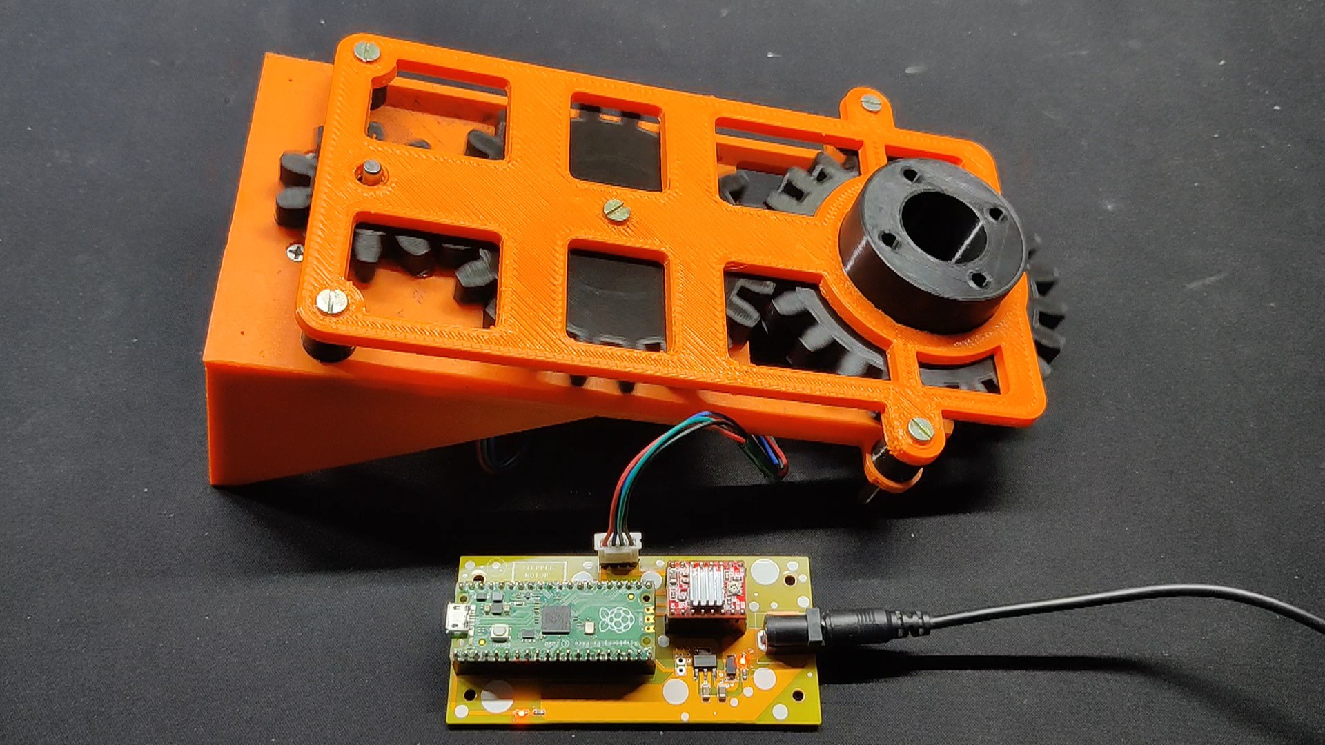
We developed a gearbox for the stepper motor test, which will be used in a future project. This driver circuit is just a part of that project.
- A gearbox with three gears—two 22-teeth gears with a 5mm modulus and one 10-teeth gear with the same 5mm modulus—is included here. We used a Nema17 stepper motor that we salvaged from an old Anet A8 3D printer to connect the smaller 10-teeth gear.
- We connected the stepper motor's wire harness connector to the driver's CON4, which is connected to the A1, A2, B1, and B2 terminals of the A4988 driver.
- The motor begins to rotate when the device is switched on by plugging the DC jack of a 12V 2A power adapter into the circuit, via DC barrel jack.
-
4CONCLUSION
![]()
This small yet practical project has resulted in a Stepper Motor Driver Board that can run almost any stepper motor. It is powered by the Pico and only needs a 12V input. Theoretically, we could just replace the A4988 Motor driver with another Stepper Motor driver board because most of them have the same footprint.
The Onboard Raspberry Pi Pico makes things incredibly easy to control; we can just connect the Pico with our computer and edit the code, make modifications, and then drive the motor with the 12V power adaptor.
This is it for today, folks. All the documents related to this project are attached, which you can checkout in this article. If you need any additional information, feel free to leave a comment, and I will be happy to assist you.
Special thanks to HQ NextPCB for providing components that I've used in this project; check them out for getting all sorts of PCB or PCBA-related services for less cost.
Thanks for reaching this far, and I will be back with a new project soon.
Pico Stepper Motor Driver Board
Raspberry Pi PICO with A4988 Stepper Motor Driver Setup
 Arnov Sharma
Discussions
Become a Hackaday.io Member
Create an account to leave a comment. Already have an account? Log In.