 uhpowerup
This is update to Blue Dmod prototype. now in PCB form with few changes.
See https://hackaday.io/project/199343-blue-dmod for first attempt.
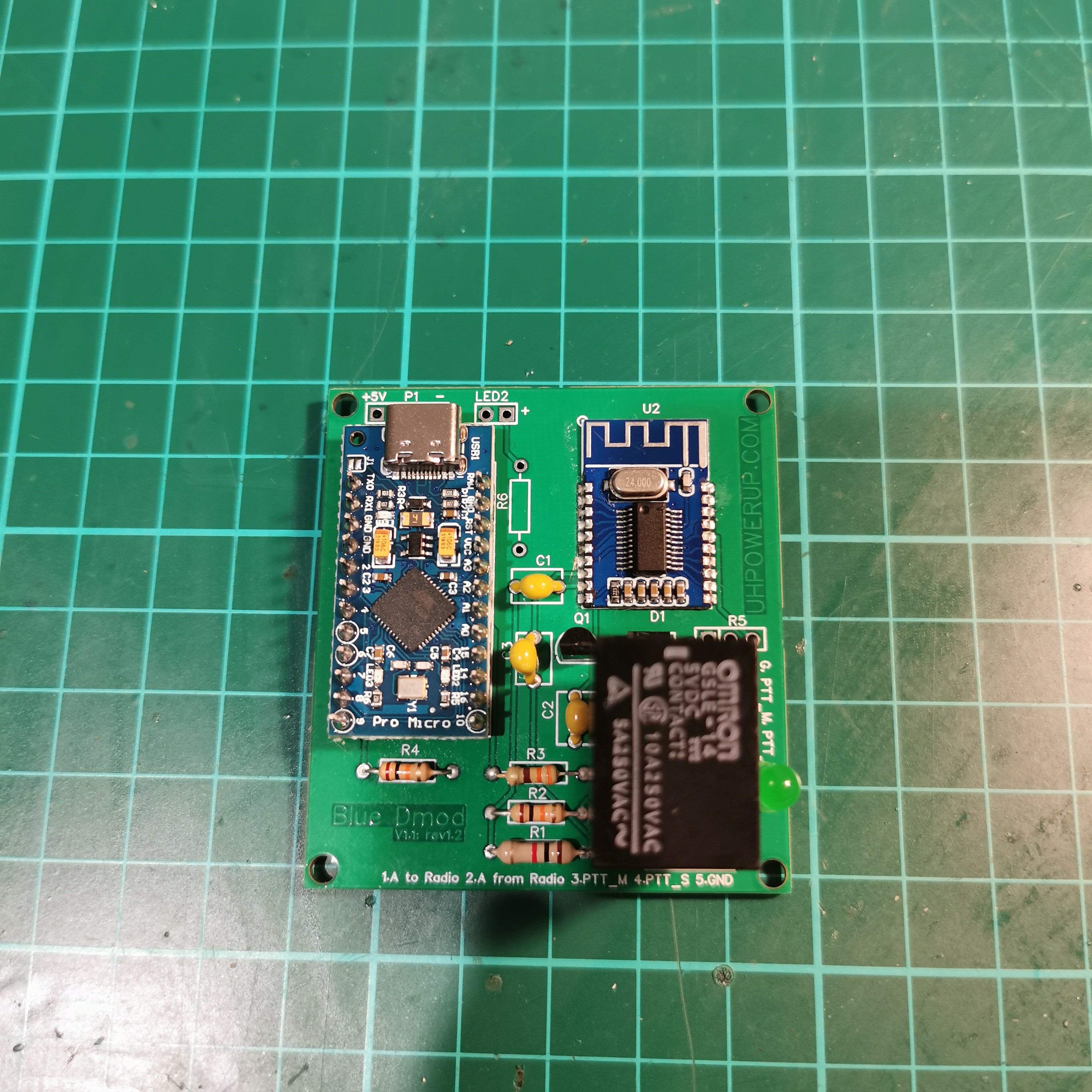
Proper PCB design and less components for updated Blue Dmod.
Already have an account? Log in.
To make the experience fit your profile, pick a username and tell us what interests you.
This is update to Blue Dmod prototype. now in PCB form with few changes.
See https://hackaday.io/project/199343-blue-dmod for first attempt.
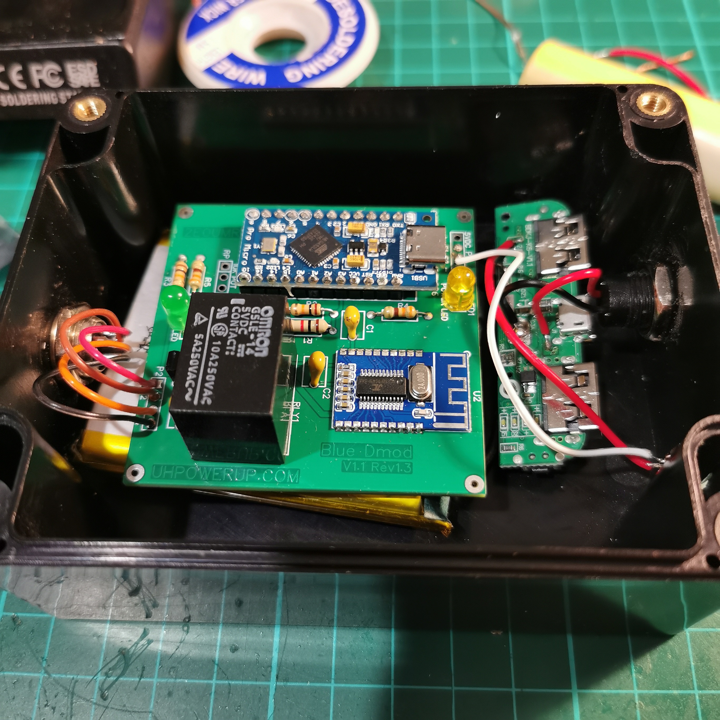
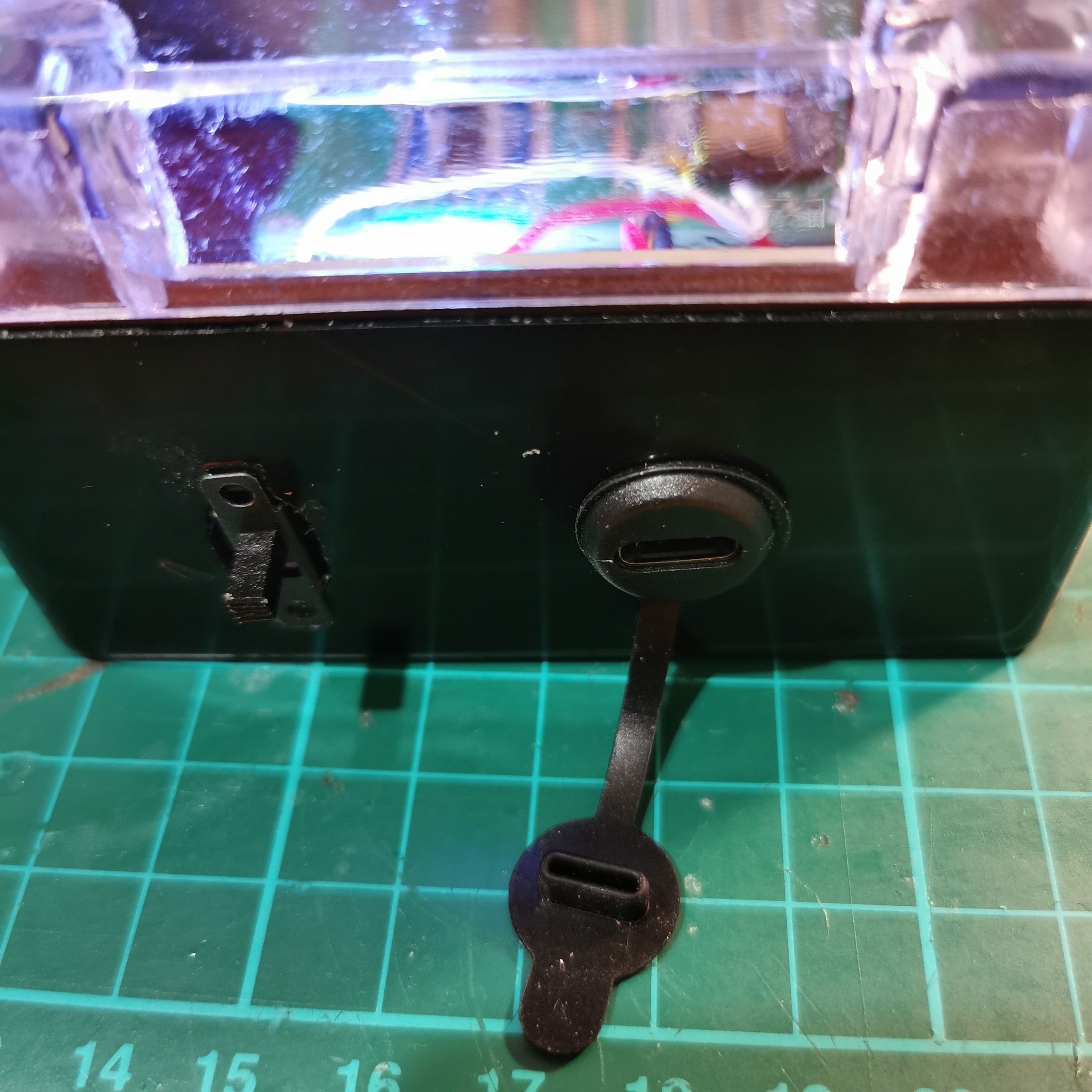
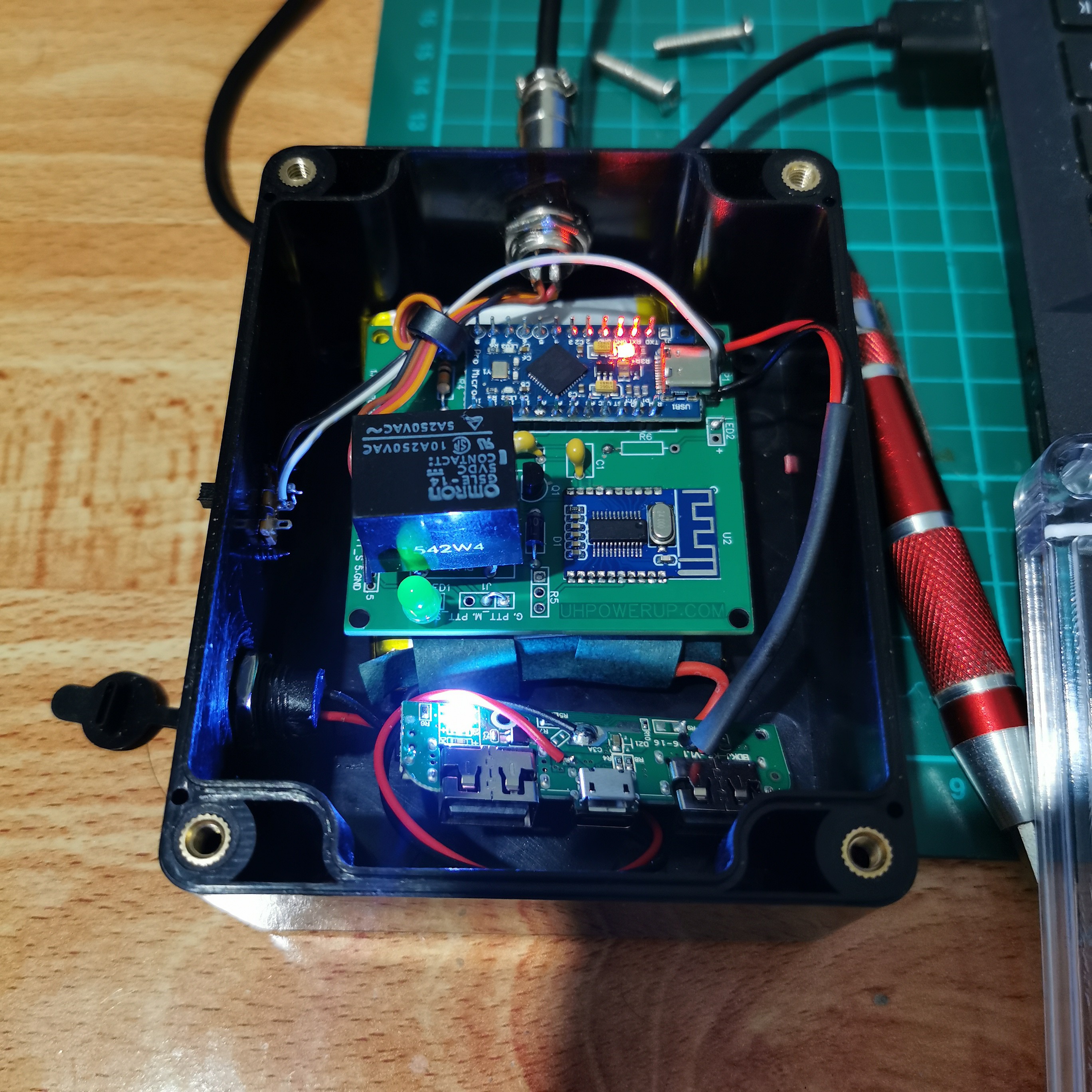
V1.1 rev1.3 have fault free PCB “Size:60x60mm” which were in V1.1 rev1.2(deleted due to PCB errors). Once assembled you can choose whether to power it up straight from 5V (USB/Power bank) have a 5V out battery. I have tested few 3.7V battery charge and 5Vboost circuits but as they have a low current shutoff didn’t work out as they shut down after 10 seconds of boot up. My work around is to buy a cheap power bank which are typically sold at local grocery shops for £5 to £10 they don’t have any low current shut off circuit. I had to remove the casing of power bank to fit in my box which is 115x90x55mm.
How it works:
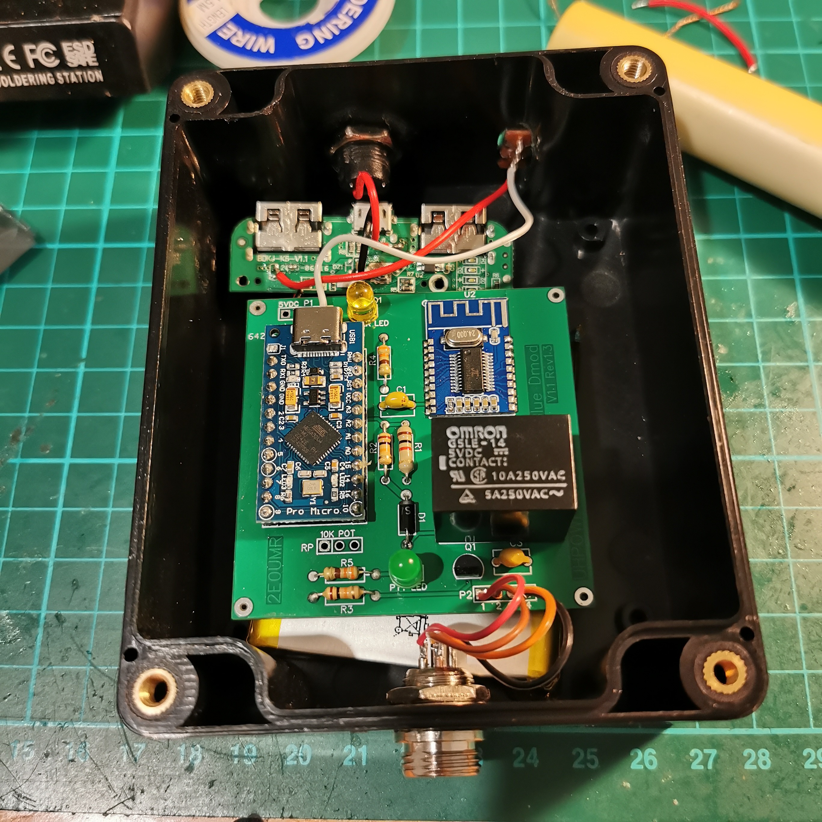
Audio from Radio (from I/O pin1) is sent to Bluetooth Mic input. Audio from Bluetooth Left channel is used to send data to Radio on I/O pin 2. Audio from Bluetooth Right channel is sent to Pro micro via voltage divider. Pro micro is programmed to sense the voltage rise from Right channel. Once volage cross the threshold PTT is triggered on I/O pin 3. PTT is stay on till the voltage get blow threshold. You can set the time of PTT trigger via 10K pot or default at 1000 ms (2 separate programming files provided).
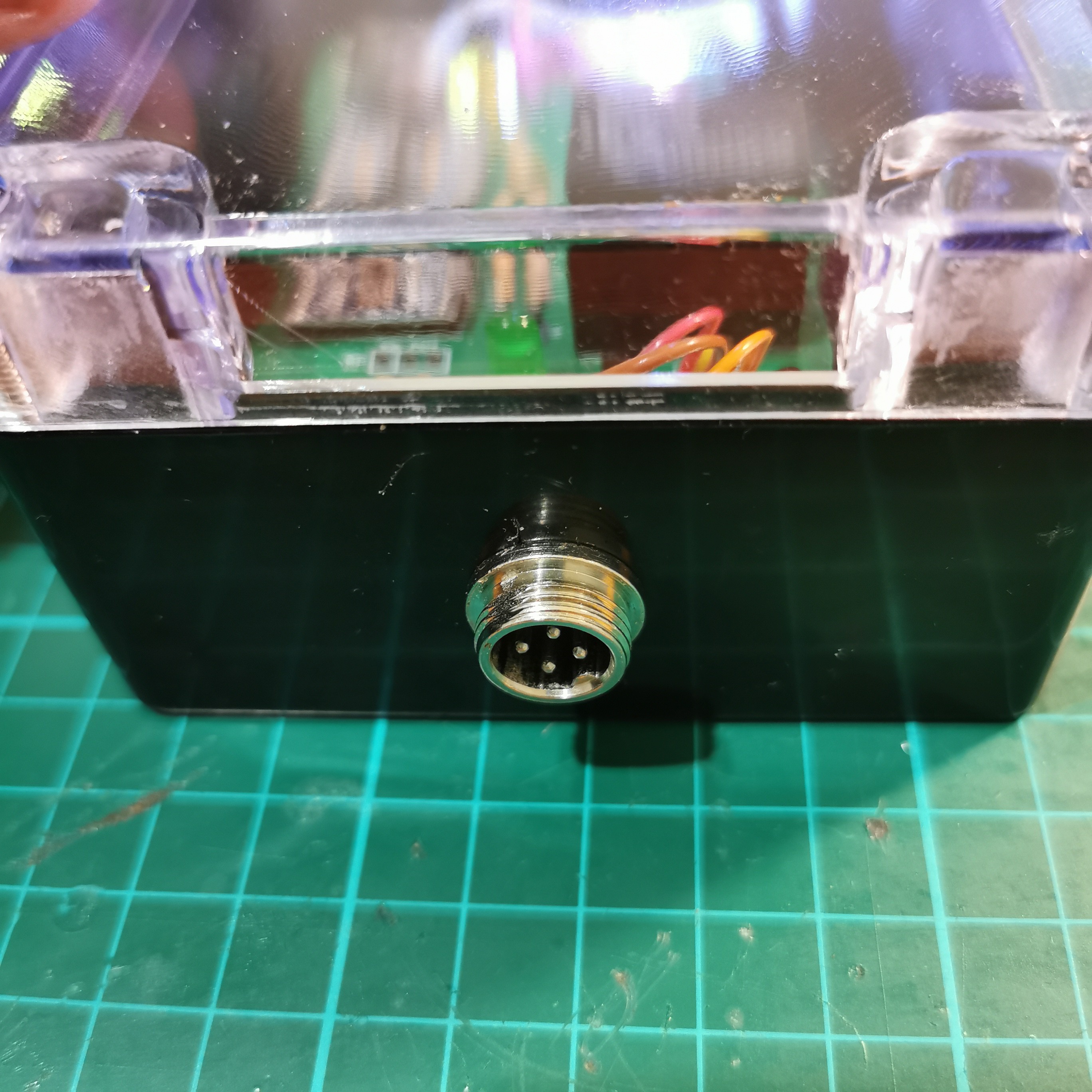
I/O connector:
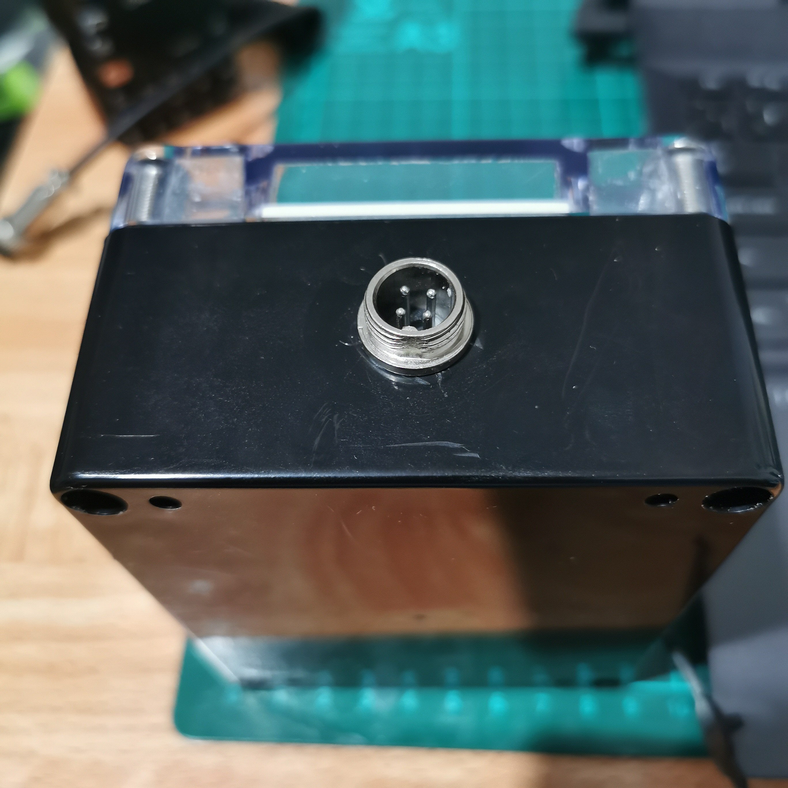
You can choose your own connector for I/O from RJ45 Port, GX12, M12 or any thing that works for you.
Operation:
Paring (first time):
Make sure radio is not connected with Blue Dmod. Turn on Blue Dmod, on your Smartphone/Tablet/PC turn on Bluetooth. Blue Dmod will show up as “Bluetooth Audio”. Pair it with your device (PTT will trigger once or twice as the Bluetooth have built in sound with triggers the PTT).
Normal operations:
Make sure the radio is not connected to Blue Dmod and turn on the Blue Dmod. PTT will trigger once or twice due to Bluetooth’s internal audio for bootup and connecting toa device. Connected the Radio. Open the app/program you want to use make sure the volume know on the radio is adjusted to proper volume. When you will send data from the app Blue Dmod will automatically trigger PTT of the radio for transmission.
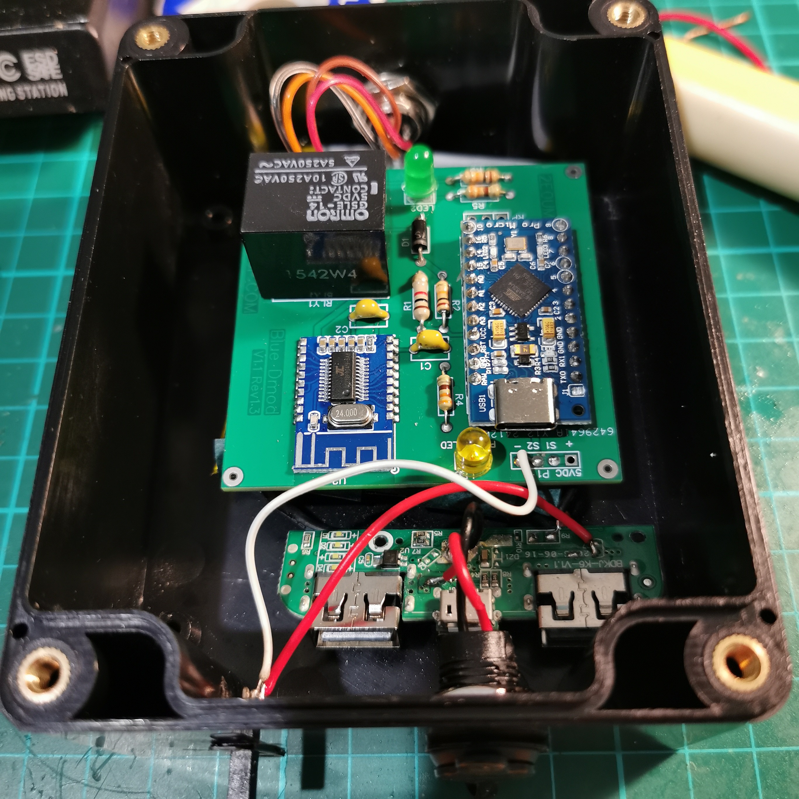
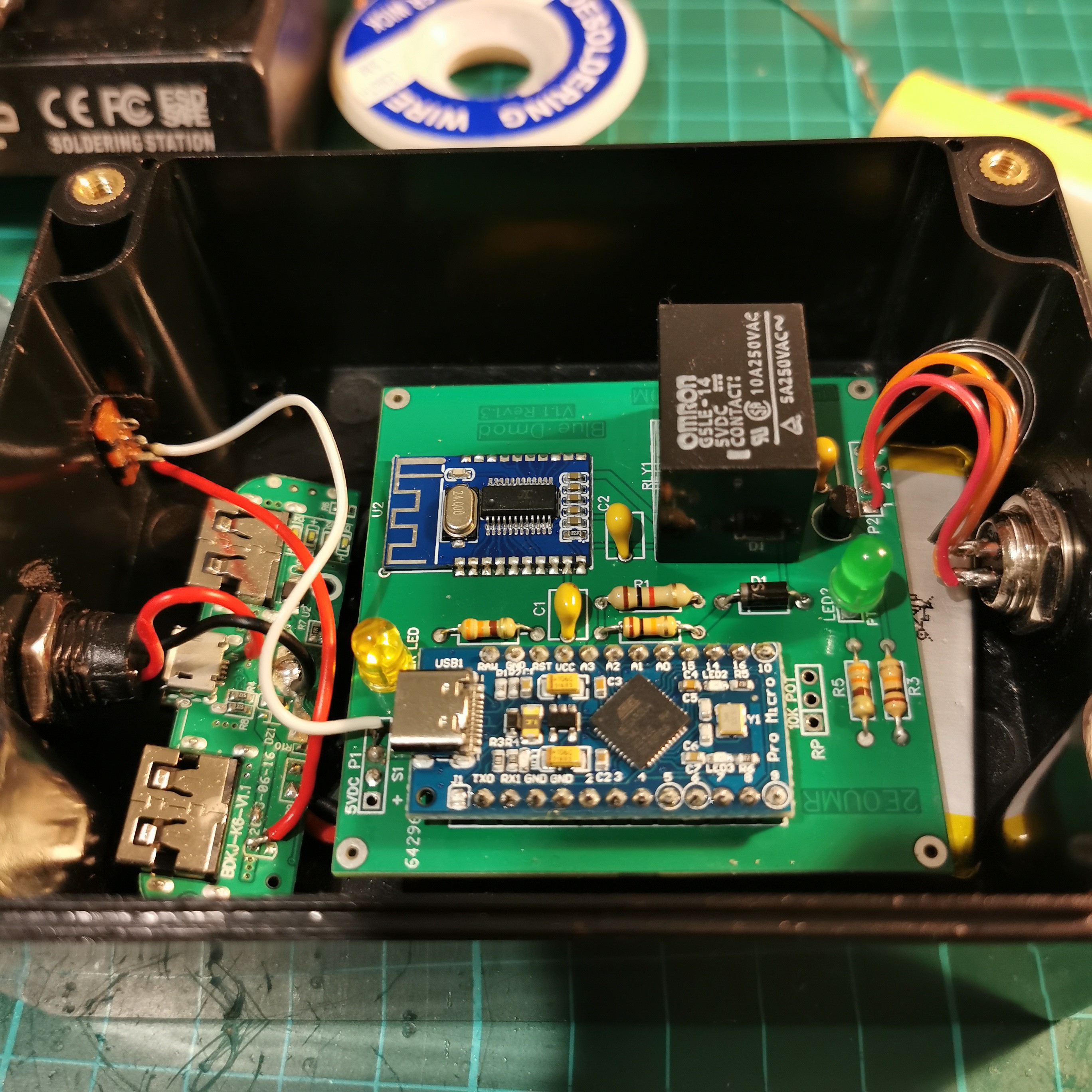
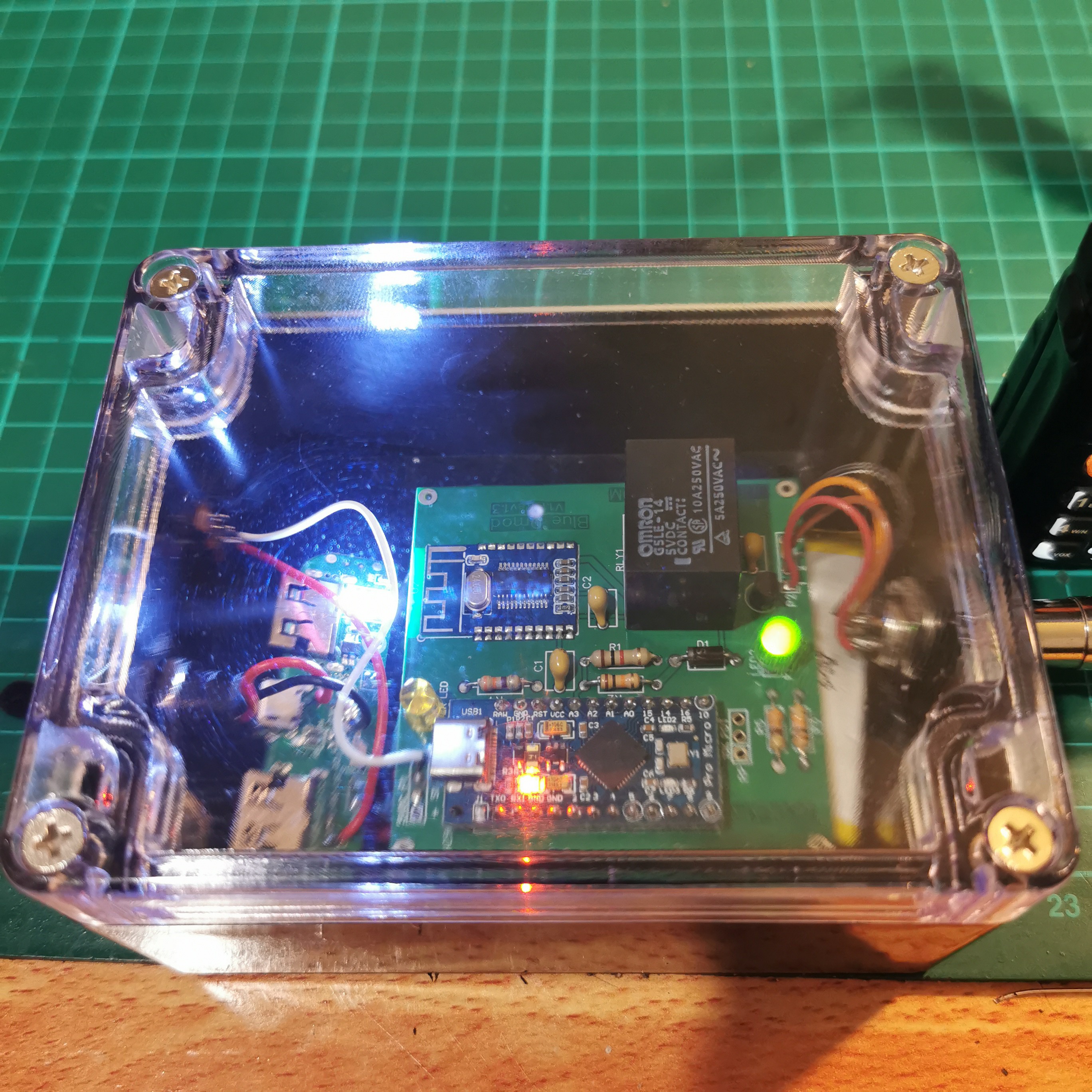
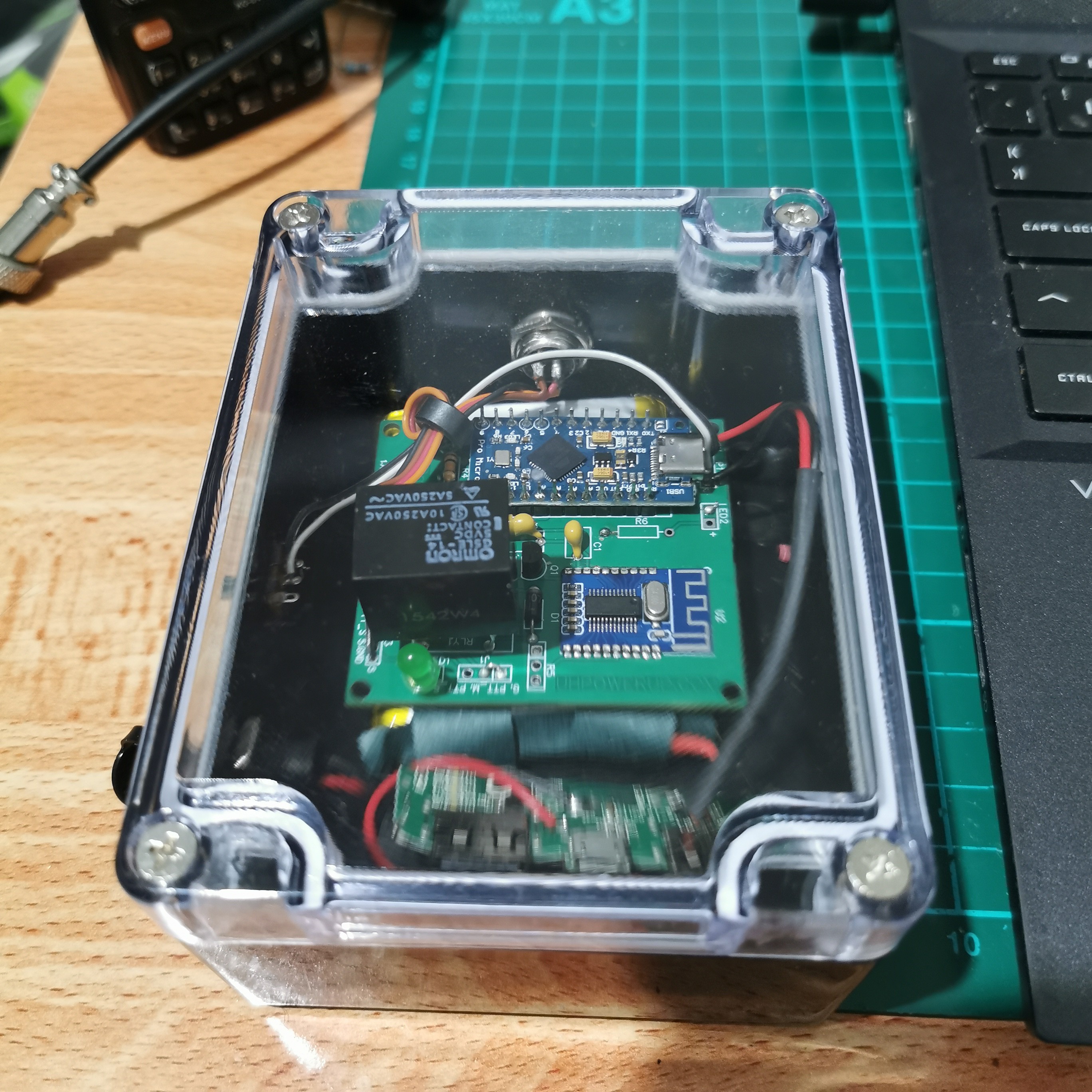
Internal Photos:
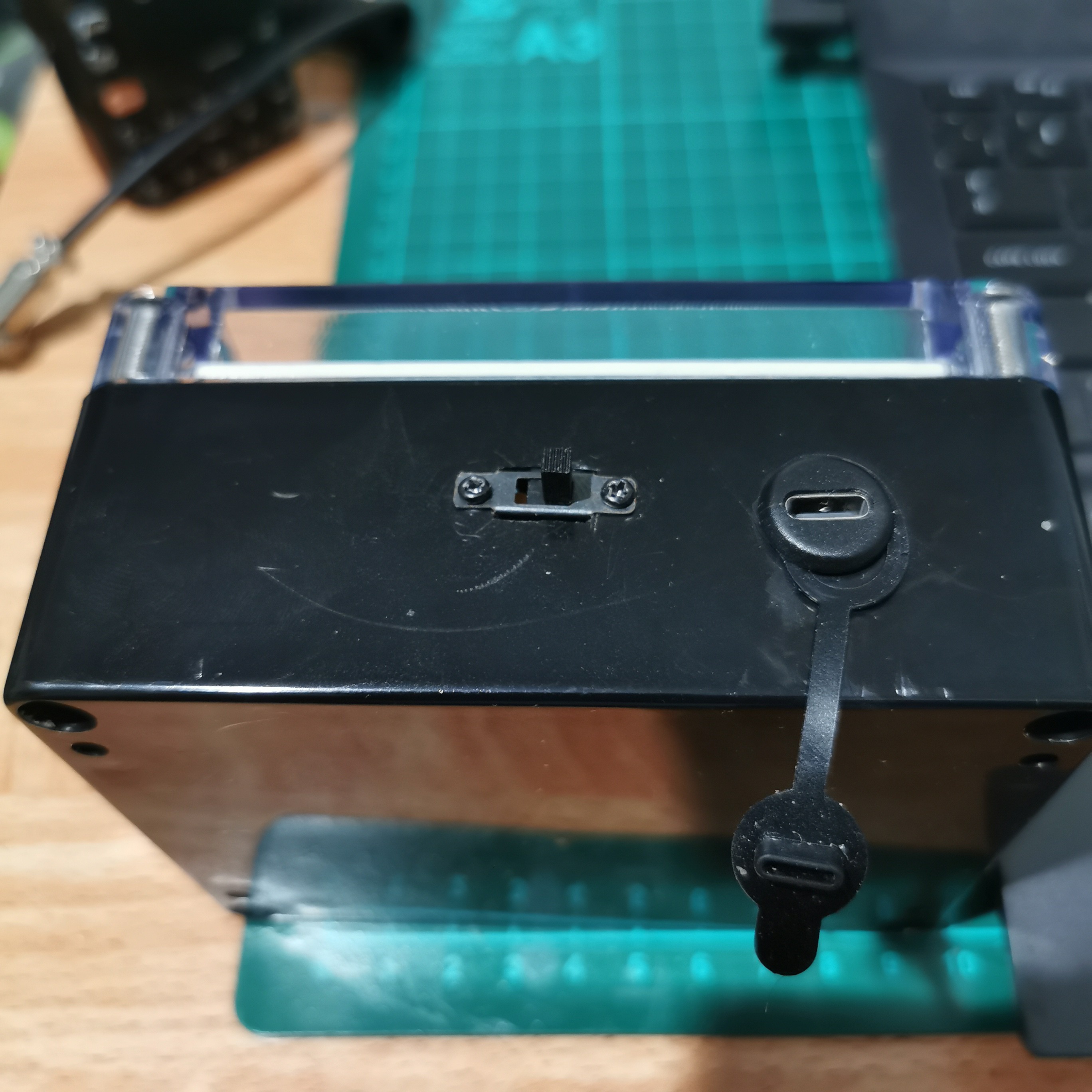
Box Photos:
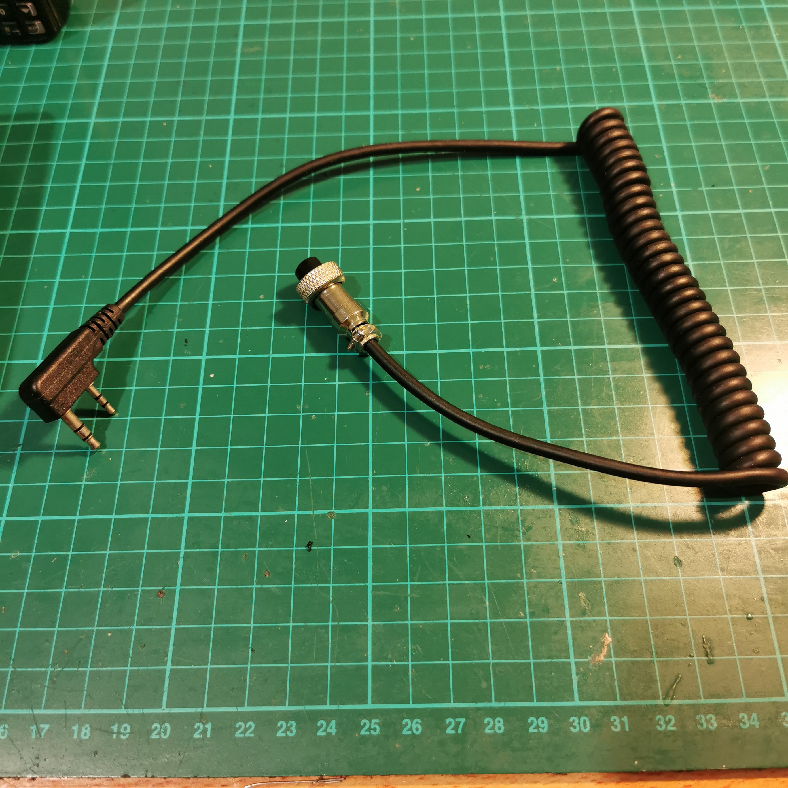
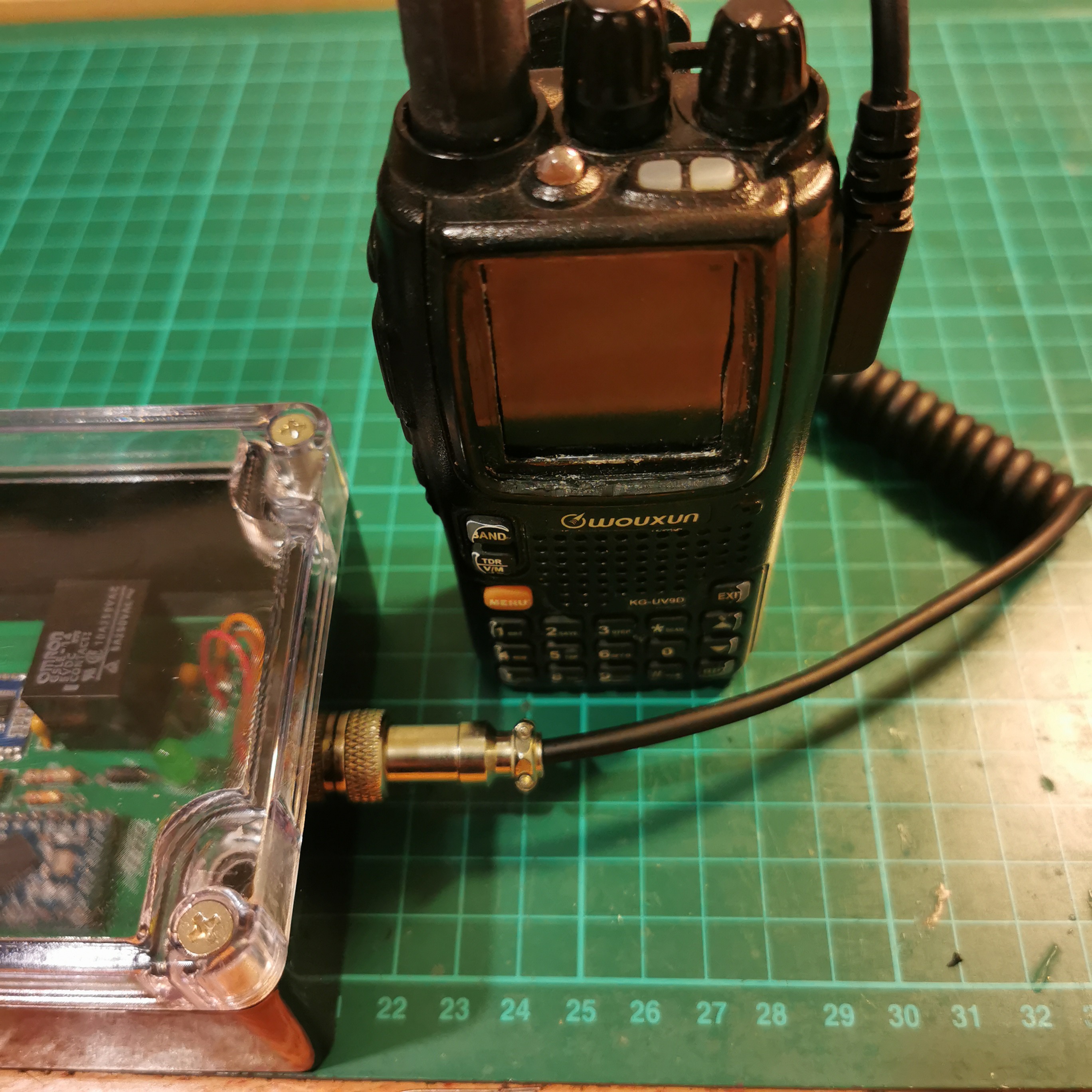
Blue Dmod Connected to Wouxun KG-UV9D:
Known Issues:
PTT keep getting triggered: If Blue Dmod is placed next to Antenna port, the tx radiation might trigger the Bluedmod on its own until powered off. Also, if the I/O cable is long and is next to transmission line/ antenna it might show abnormal behaviour.
73's
2E0UMR
New PCB just arrived, will upload files after tests. also modified old PCB and tested all worked as expected. Still trying to find a Power boost circuit without low current shut off. Found easy way to use cheap power bank to power the circuit.
Moded PCB removed a pad on the left side of Bluteooth module. also Relay pads were small size.
Assembled PCB and testing.
Will keep you posted.
73's
2E0UMR.
While assembling the PCB few faults were discovered, Old PCB is scraped. New design will be posted soon. I’m still learning PCB design. Apologies for delay.
PCB arrived, Will be soldering components.
PCB had a issue, new PCB have a cut out for Bluetooth antenna to reduce interference.
You can choose any of the code if you would like to potentiometer then use "BlueDmod-1.1_rev1.2_POT".
if you do not want to use potentiometer then use "BlueDmod-1.1_rev1.2_non_POT" a default delay of 1000ms is implemented.
With careful consideration and few feed backs, I have decided not to hard mount the I/O port on PCB. It will be 5 pin unpopulated header you can choose to connect appropriate connector or hard wire it to your Radio. My best suited option for ports is M12 data connector, GX12 aviation connector or RJ45 port.
In addition, I have left the power system alone will be totally users’ discretion. You can use “MH-CD-42” Charging and 5VDC booster module.
User can use “J1” jumper setting to select PTT_M to contact Ground when PTT is triggered or have PTT_S if the radio PTT is triggered using internal pins.
Previously uploaded Pictures will be replaced by new ones.
Will keep everyone updated on further developments.
73’s
2E0UMR
Designed the PCB and reduced few component's like CW 025 relay module, driving 5VDC relay directly from Pro Micro using BC547 Transistor. Added a 10K pot to select the Delay of Relay switching (prototype was only possible via code). Using new BT003 Bluetooth module as SMD.

 PUTMotorsport
 aysenurkarga
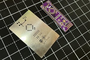
 Sagar 001
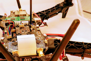
 Laetitia BEL