-
Featherwing Format
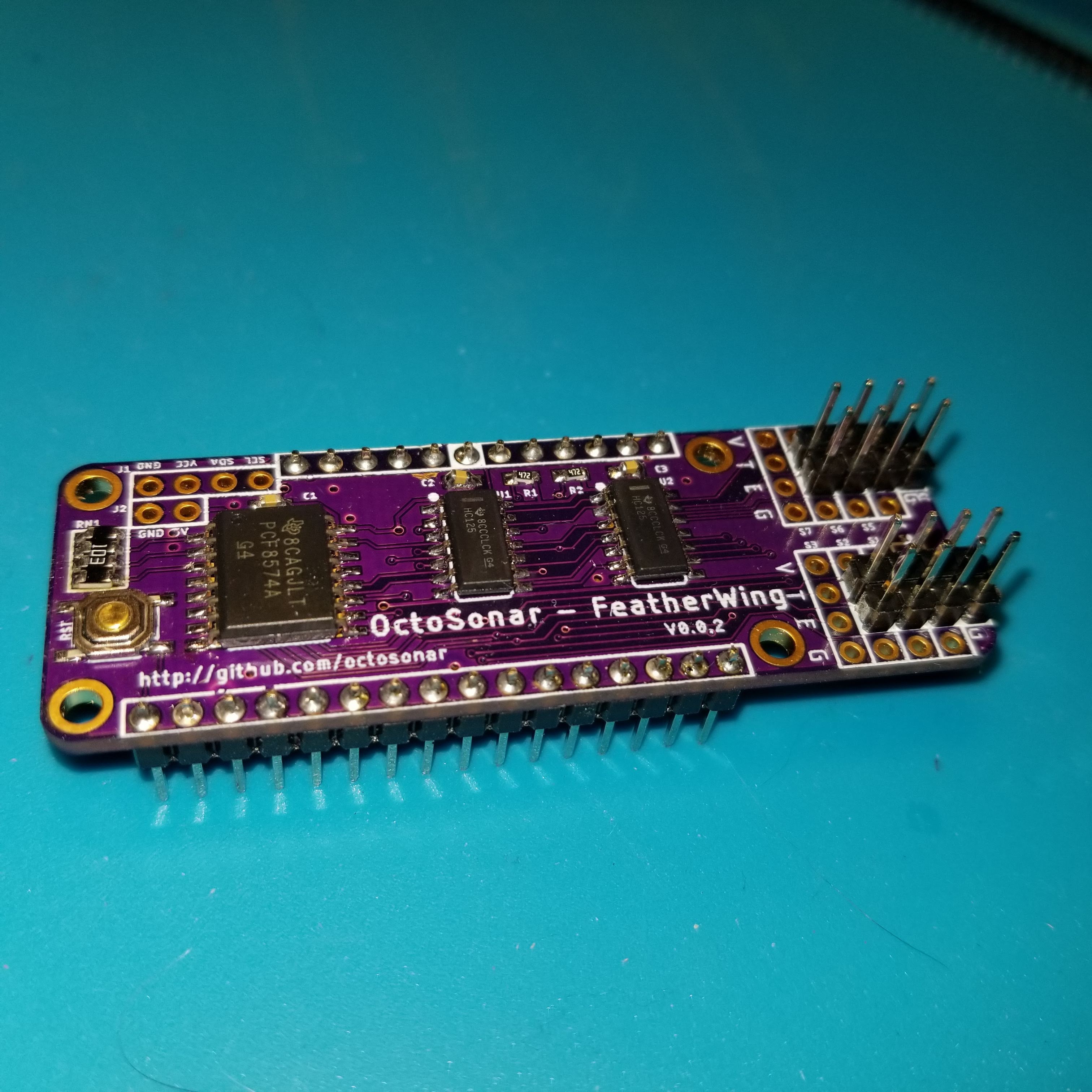
05/10/2022 at 18:59 • 0 commentsSOme time ago I updated the design to featherwing format. It is still usable via a cable connection, but now it can also be plugged directly onto a Feather format controller.
I also turned the camera on while making the most recent batch. While I do need to work on my camera skills it does show the end to end process of making these boards along with testing and packing.
![]()
-
V3?
11/14/2019 at 03:13 • 0 commentsSo I'm in the process of redesigning the boards for the featherwing footprint. This should make them easier to use for feather adherents, as well as smaller in general. Keeping the ability to be wired standalone. These are in separate projects for entry into the current hackaday contest.
This has got my brain clicking that what I should really do is to put an ATTiny on the boards and run the code locally. This will make it much easier to use with non-Arduino platforms - save me learning how to do hardware interrupts on RPi for instance.
An ATTiny85 would not have enough pins even to drive a shift register and I2C and retain the reset pin so I'm thinking ATTiny841. On the 8 port board that has enough pins to drive the sensors directly, and it will fit in where the PCF8574 is on the feather footprint. For the 8 port I could either go with a more-pins ATTiny or go with shift registers and an ATTiny 841. As the sensor headers and the tristate buffers are all on the featherwing added footprint, there is lots of space to do that within the new form factor. And using shift registers allows for daisy chaining for people that want to use silly quantities of sensors. (like 16 isn't silly enough?)
Will have to bit-bang the shift register as the SPI overlaps the I2C on all the Tiny chips I'm looking at.
Naming is problematic
maybe Octosonar3/8 and Octosonar 3/16 ?
-
Archived V1 instructions
09/16/2018 at 21:55 • 0 commentsArchiving the original V1 board and no-board prototype instructions here.
THIS IS NOT CURRENT
Hardware
The minimum setup to use this usefully requires
- a PCF8574 or PCF8574A IC
- two HC-SR04 sensors
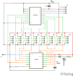
- two NPN transistors and some resistors to make a NOR gate
- example sketch SonarI2Cv2
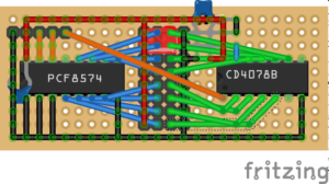
![basic breadboard test]() Software
SoftwareIf you are using version 1.6.2 or later of the Arduino software (IDE), you can use the Library Manager to install this library:
- In the Arduino IDE, open the "Sketch" menu, select "Include Library", then "Manage Libraries...".
- Search for "SonarI2C".
- Click the SonarI2C entry in the list.
- Click "Install".
If this does not work, you can manually install the library:
- Download the latest release archive from GitHub and decompress it.
- Rename the folder "SonarI2C-master" to "SonarI2C".
- Move the "SonarI2C" folder into the "libraries" directory inside your Arduino sketchbook directory. You can view your sketchbook location by opening the "File" menu and selecting "Preferences" in the Arduino IDE. If there is not already a "libraries" folder in that location, you should make the folder yourself.
- After installing the library, restart the Arduino IDE.
(note - the above instructions adapted from a Pololu readme)
HC-SR04 I2C Octopus "octosonar"
There was enough interest in these that I made up a small batch to sell on Tindie.
![]()
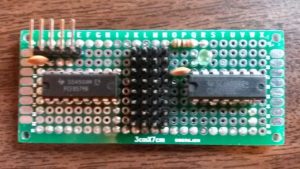
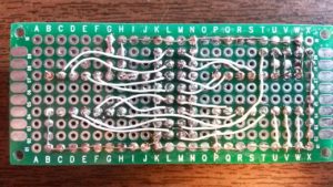
To test these without the headers attached, I made up a test-bed on an Arduino proto-shield. This tests all the power pins (the green LEDs), checks the outputs from the PCF8574A and feeds signals into the CD4078 and verifies the output.
![]()
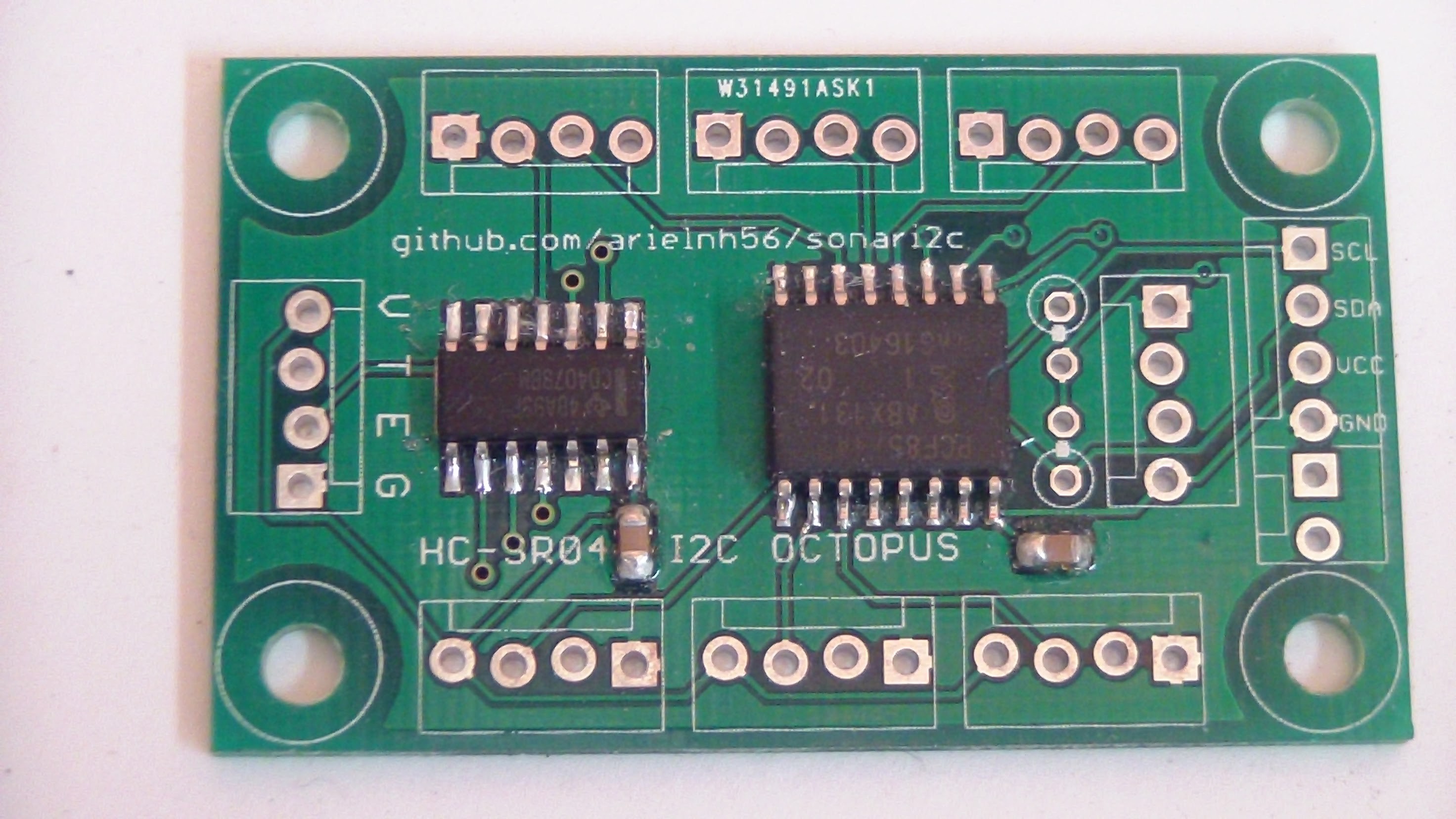
There is a minor error on these boards in that the silkscreen "Name" layers are missing so it does not show what port is which. Refer to the image below.
![]()
IMPORTANT: There are no pull-down resistors on the Echo inputs. Jumper any unused ports from E to G or you will get very erratic results.
The 8 Port Prototype
Download the current SonarI2C library code on GitHub
HC-SR04 I2C Octopus "octosonar"
There was enough interest in these that I made up a small batch to sell on Tindie.
![]()
To test these without the headers attached, I made up a test-bed on an Arduino proto-shield. This tests all the power pins (the green LEDs), checks the outputs from the PCF8574A and feeds signals into the CD4078 and verifies the output.
![]()
There is a minor error on these boards in that the silkscreen "Name" layers are missing so it does not show what port is which. Refer to the image below.
![]()
IMPORTANT: There are no pull-down resistors on the Echo inputs. Jumper any unused ports from E to G or you will get very erratic results.
-
OctoSonarX2 and Trimounts now shipping
10/03/2017 at 04:56 • 0 commentsThe first batch of the OctoSonarX2 units are built, tested and ready to ship.
https://www.tindie.com/products/10614/
![]()
The Trimounts are also sorted into little baggies in sets of four
https://www.tindie.com/products/10615/
![]()
![]()
-
OctoSonar 1.1.0 code release
07/27/2017 at 05:53 • 0 commentshttps://github.com/arielnh56/OctoSonar/releases
1.1.0 adds support for the 16 port OctoSonarX2
-
HC-SR04 Trimount and OctosonarX2 demo video
07/26/2017 at 06:46 • 0 commentsTrimounts and OctosonarX2 demo video
-
The OctoSonarX2 Board Works!
07/23/2017 at 03:27 • 0 commentsI needed to tweak the software a bit - an update release is on the way. Fun with derived C++ classes!
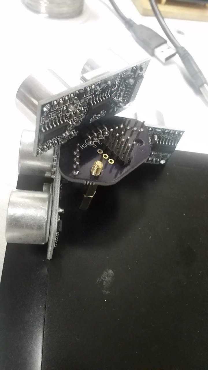
Anyhoo the thing works with 12 units on 4 trimounts. I'll pick up a new piece of acrylic tomorrow to mount this all on.
![]()
-
Trimount HC-SR04 brackets work
07/21/2017 at 17:13 • 0 commentsBut need a little tweaking. The diagonal unit should be pulled back a little, to keep the unit within the same overhang as the rectilinear ones, and the corner hole needs a little more clearance.
![]()
![]()
![]()
-
Widening the range
07/06/2017 at 05:32 • 0 commentsThe v2 board is faster with normal HC-SR04, cutting off the 200ms no-echo units at 50ms, and doing the same with the bad units that never come back, but that doesn't address the blind spots at the corner of the robot or the hassle of handcrafting mounting brackets.
The code does support multiple boards but that's klunky.
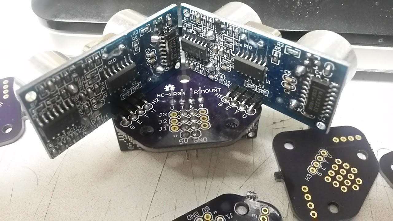
I just fired off prototype designs to OSHPark for a 16 port board based on the PCF8575 and a little board to mount 3 HC-SR04 on each corner - with two at right angles on one side and a third at 45 degrees on the other. The idea is to mount it on standoffs.
The extra V and G pins on the connector blocks should allow the three sensors to be run from 2 4-pin cables by inserting them at right angles.
Any interest? Comments welcome!
![]()
![]()
![]()
-
v2.1 boards are built
06/26/2017 at 01:11 • 0 commentsThe new boards are built and a very pretty blue they are.
I mounted one up on the greenbot and it works as designed.
I made up a test jig and an arduino sketch to wiggle all the pins and watch them from another PCF8574.
I did run into some timing issues reading from the jig, but those went away when I turned off the Serial.println commentary. I'm thinking there is some weird interaction between the Wire and Serial libraries.
![]()
Pictures in the gallery
HC-SR04 I2C Octopus "octosonar"
Connect up to 16 ultrasonic range sensors to an Arduino with I2C bus and one pin
 Alastair Young